

Secure, robust closed network, with up to 2 connected
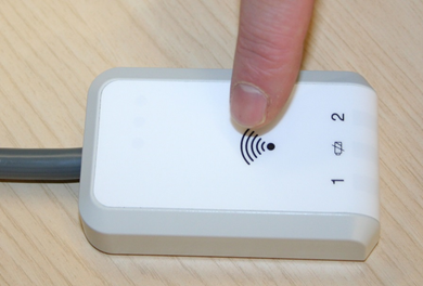


Bluetooth to USB 2.0 Housed Receiver
Secure PAN (Personal Area Network), with up to 2 transmitters
Emulates keyboard or mouse function (preset during manufacturing process)
Plug and play technology, no additional drivers required
Works with Windows, Linux and Mac operating systems
10 cm of cable as standard
Emulation of up to 3 simultaneous keystrokes
Ultra-low power
Range: Nominally 10 m (up to 15 m line of sight, Latency may increase with range) • Selectable Latency:
Setting 1. Typically <200 ms at 10 m
Setting 2. Typically <100 ms at 10 m
LED indication of battery status • Choice of 15 or 60 minutes timeout for further battery conservation
Auto wake from sleep/re-connect on the press of the pedal

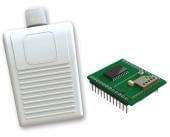
Bluetooth PCB Receiver
Secure PAN (Personal Area Network), with up to 2 transmitters.
Ultra low power with 1uA sleep current.
Range: Nominally 10 m (up to 25 m line of sight, Latency may increase with range).
Selectable Latency:
Setting 1. Typically <150 ms at 10 m
Setting 2. Typically <75 ms at 10 m.
LED indication of battery status.
Choice of 15 or 60 minutes timeout for further battery conservation.
Auto wake from sleep/re-connect on press of the pedal.
HERGA Bluetooth® Smart Footswitch System
Chapter 1: Introduction, Warranty, and Safety Instructions
1. Important Information
Purpose
This manual provides instructions for the use of HERGA’s Bluetooth® Smart Footswitch System. It includes safety guidelines, installation instructions, usage details, and maintenance requirements.
Please read this manual carefully before using the system, as improper usage may cause damage to the device or harm the user.
Manufacturer Warranty
HERGA offers a one-year return-to-base warranty on manufacturing materials and workmanship, effective from the date of delivery.
The warranty covers the repair or replacement of defective components free of charge, excluding batteries, provided the system is used correctly and within specified guidelines.
Note: Any unauthorized modifications to the system will void the warranty. HERGA is not responsible for damages caused by tampering or alterations performed by unqualified personnel.
2. Scope of the Manual
This manual applies to the following HERGA Bluetooth® Smart products:
- 6311-BLE2-xxx: Bluetooth® Smart Receivers.
- 6210-BLE2-xxx: Single Pedal Footswitch Transmitters.
- 6226-BLE2-xxx: Multi-Pedal Footswitch Transmitters.
- 6241-BLE2-xxx: Multi-Pedal Puck Switch Transmitters.
3. Safety Instructions
Warning and Information Definitions
- Warning: Critical information about a potentially hazardous situation that could result in death or serious injury if not avoided.
- Caution: Information about a situation that could result in minor or moderate injury or damage to the equipment.
- Important: Guidelines or notes that should be carefully followed to ensure proper usage.
Intended Use
- The system is designed to integrate with OEM (Original Equipment Manufacturer) electrical equipment.
- It must not be used as an emergency stop device in machinery.
- Only qualified and trained personnel should operate the system. It should never be used by patients or untrained individuals.
General Warnings
- Explosion Hazard: Do not use this system in environments containing flammable substances.
- Medical Applications: Ensure that the system complies with strict medical safety standards if integrated into medical equipment.
- Electromagnetic Interference (EMI): In environments with many RF-emitting devices, evaluate the system for potential interference and take appropriate steps to mitigate it.
Additional Recommendations
- Include audible or visual indicators in the system for feedback during footswitch activation.
- Provide backup mechanisms for system deactivation in the event of a critical failure.
- Regularly inspect the system components to ensure durability and reliability.
4. System Overview
System Components
- Bluetooth® Smart Footswitch (Transmitter): Battery-operated (2x AAA), featuring LED indicators for connection and battery status.
- PCB Receiver: Designed for seamless integration with OEM electrical systems, offering multiple output options.
- Housed Receiver with Relay Outputs: Suitable for applications requiring external relay connections.
Key Features
- Operating Range: Up to 15 meters (line of sight).
- Battery Life: Over 1,000 hours of continuous operation.
- Water Resistance: Rated IPX7 for high water resistance.
- Status Indicators: LED lights for connection, battery, and operational states.
- Simple Pairing: Dedicated pairing button to prevent accidental activation.
5. Pre-Installation Guidelines
Preparation
- Ensure that installation is performed by qualified personnel only.
- Keep this manual accessible for future reference.
- Do not attempt to open or modify the footswitch. No user-serviceable components are inside.
Cleaning
- Clean the device with a damp cloth and mild soap.
- Isopropyl alcohol (70%) can be used for disinfecting if necessary.
Note: Avoid chlorine-based cleaning agents, as they may damage the device.
6. System Setup and Operation
Preparing the Footswitch (Transmitter)
Installing Batteries:
- Open the battery compartment using a small screwdriver.
- Insert two high-quality AAA alkaline batteries, ensuring correct polarity.
- Close the compartment securely to maintain water resistance (IPX7).
Battery Guidelines:
- Only use batteries of the same type and manufacturer.
- Avoid mixing new and old batteries.
- Remove batteries if the device is not used for an extended period to prevent leakage.
Initial Setup
- Ensure the system operates within the allowed temperature range (-20°C to 60°C).
- Avoid placing the antenna near metals or materials containing metal flakes to prevent signal disruption.
7. Pairing the Transmitter and Receiver
The pairing process ensures a secure connection between the footswitch (transmitter) and the receiver.
Steps for Pairing:
- Press the pairing button inside the transmitter’s battery compartment.
- The blue LED on the transmitter will start blinking.
- Press the pairing button on the receiver.
- The corresponding LED on the receiver will start blinking.
- Once the transmitter and receiver detect each other, their LEDs will light up for 5 seconds.
- Press the transmitter’s pairing button again to confirm the connection.
- The LEDs will blink three times to indicate successful pairing.
Note: If the process fails within 30 seconds, the system will enter sleep mode and require restarting the pairing process.
8. Unpairing (Removing the Connection)
Scenario 1: The Transmitter is Active and Within Range
- Press and hold the transmitter’s pairing button for 5 seconds.
- The blue LED will light up for 3 seconds and turn off, indicating unpairing is complete.
Scenario 2: The Transmitter is Not Active or Missing
- Press and hold the receiver’s pairing button for 5 seconds.
- The corresponding LED on the receiver will turn off, indicating the transmitter has been removed from the network.
9. Regular Maintenance
Routine Checks
- Inspect the footswitch weekly to ensure:
- Proper activation when pressed and deactivation when released.
- The housing is intact and not damaged.
- Replace batteries at least once a year, even if the system is operational.
- Inspect the gasket during battery replacement for signs of wear or damage.
Cleaning
- After cleaning, dry the device with a lint-free cloth or an industrial hot-air dryer.
10. Receiver Features
Technical Characteristics
- Digital Outputs (Pins 17–24): Compatible with relays or microcontroller inputs.
- PWM Output: Provides a digital signal proportional to footswitch movement (not for direct motor control).
- LED Indicators: Connection status, battery level, and pairing status.
11. System Troubleshooting
Normal System States
The following table describes standard LED indications and their meaning:
| LED Status | Description |
|---|---|
| Solid blue LED on the receiver | The transmitter is connected and operating normally. |
| Fast blinking blue LED | The transmitter is out of range, or the connection has been lost. |
| Yellow LED blinking on the transmitter | Battery level is low—replace the batteries immediately. |
Common Issues and Solutions
| Issue | Possible Cause | Recommended Action |
|---|---|---|
| No connection between the transmitter and receiver | Pairing not completed, or interference exists | Perform the pairing process again. Ensure no obstacles or interference between devices. |
| The transmitter does not respond | Batteries are depleted, or incorrectly installed | Check and replace the batteries. Verify polarity. |
| Receiver outputs are not functioning | Incorrect wiring or overload on output pins | Verify connections and ensure load is within limits. |
| Connection drops intermittently | Electromagnetic interference or low battery in the transmitter | Replace batteries and move devices away from interference sources. |
12. Detailed Technical Specifications
General Parameters
| Parameter | Value |
|---|---|
| Operating range | 5–15 meters (line of sight, depending on the environment) |
| Transmitter battery life | Over 1,000 hours of continuous operation |
| Operating frequency | 2.402–2.480 GHz (ISM band) |
| Water resistance (transmitter) | IPX7 |
| Storage temperature | -20°C to 70°C |
| Operating temperature | -20°C to 60°C |
| Receiver input voltage | 5–24 V DC |
Receiver Outputs
- Digital Outputs: Open Collector NPN outputs.
- Voltage range: 5–24 V
- Maximum current: 100 mA per output
- PWM Output: Provides a proportional signal for external circuit control (not suitable for direct motor control).
Additional Features
- AES 128-bit encryption for secure communication.
- Adaptive Frequency Hopping minimizes interference in crowded RF environments.
- Smart Battery Alerts: LED indications signal low battery status with increasing urgency.
13. Pairing and Connection Monitoring
Pairing Procedure
- Start pairing on the transmitter:
- Open the battery compartment and press the pairing button.
- The blue LED on the transmitter will begin blinking.
- Activate pairing on the receiver:
- Press the pairing button on the receiver.
- The receiver’s LED will blink, indicating it’s searching for the transmitter.
- Complete the connection:
- Once detected, the LEDs on both devices will light up solid for 5 seconds.
- Press the pairing button on the transmitter again to confirm the pairing.
- LEDs will blink three times to indicate successful pairing.
Connection Status via LEDs
- Solid blue LED on the transmitter: Secure connection established.
- Slowly blinking blue LED: The transmitter is searching for a connection.
- Rapidly blinking blue LED: The transmitter is out of range or disconnected.
14. Regulatory Compliance
Standards and Certifications
The Bluetooth® Smart Footswitch System complies with the following international standards:
- EN 60601-1: Electrical safety standards for medical devices.
- EN 60529: Protection against water and dust (IPX7 rating for footswitches).
- IEC 60601-1-2: Electromagnetic compatibility for medical environments.
- FCC Part 15:
- The device will not cause harmful interference.
- The device must accept interference, even if it causes undesired operation.
Warnings
- Unauthorized modifications to the system components, including the antenna, may void the warranty and compliance certifications.
- For range enhancements, contact HERGA for approved high-gain antennas.
15. Product Labels and Symbols
The product and its packaging include important symbols:
- WEEE Symbol:
Indicates compliance with EU waste disposal regulations for electronic equipment. - CE Marking:
Confirms conformity with European Union directives and standards. - Temperature Range Symbol:
Specifies the permissible storage and operating temperatures. - Serial Number and Manufacture Date:
Identifies the device for warranty and support purposes.
16. Antenna Placement and Optimization
Antenna Guidelines
- Only use the antenna provided by HERGA.
- Position the antenna near a plastic external wall of the equipment for optimal performance.
- Maintain at least 10 mm of clearance from metal surfaces or conductive materials.
Interference Mitigation
- Avoid placing the system near high-powered RF devices (e.g., Wi-Fi routers, Bluetooth hubs).
- If communication issues arise, reposition the transmitter or receiver to reduce interference.
17. Maintenance and Troubleshooting Summary
Routine Maintenance
- Weekly Checks:
- Ensure the footswitch activates and deactivates as expected.
- Inspect for damage to the housing or connectors.
- Battery Replacement:
- Replace at least once a year or when the yellow LED indicates low battery.
System Reset for Issues
- If connection issues persist, unpair and re-pair the devices following the pairing instructions in Section 7.
18. Warranty and Support
Manufacturer’s Warranty
- Covers one year from the delivery date.
- Includes repair or replacement of defective parts, excluding batteries.
- Any unauthorized modifications will void the warranty.
Technical Support
For issues, inquiries, or customization requests, contact Amironik, the official HERGA representative:
- Phone: [Add phone number]
- Email: [Add email address]
19. Additional Information
- Switch Durability: Each footswitch is designed for a minimum of 100,000 activations.
- Customization Options: Colors, labels, and features can be customized based on customer requirements.