

Timeline diagram comparing a free-running gyro versus an External Sync gyro, showing how hardware synchronization aligns the gyro sampling instants with the camera frame capture moments and prevents timing offsets.

In modern navigation, stabilization and sensing systems, most engineers focus on gyro noise, drift and accuracy.
In practice, however, one of the most common causes of system failure is time error.
A gyro does not measure angle.
It measures angular rate at a very specific moment in time.
If that moment is not aligned with the camera, radar or GNSS reference, even the best gyro in the world will produce incorrect system data.
External Sync exists to solve exactly this problem.
What is the true sampling time of a gyro?
A gyro samples angular rate at discrete moments in time.
Each sample represents the rotational velocity at that exact instant.
In the G300D, sampling rates can reach up to 10,000 samples per second.
However, the critical question is not how fast it samples, but:
Who determines when each sample is taken?
In free-running mode, the gyro samples based on its internal clock.
In External Sync mode, sampling occurs exactly according to a system-defined external timing signal.
Only the second option allows the measurement to become part of a synchronized system.
Why SPI, RS-422 or UART timing is not synchronization
Many engineers assume that if they read data at a fixed rate, the system is synchronized.
In reality, this only means the data arrives at a fixed rate, not that it was measured at a fixed time.
Between the moment of physical measurement and the moment the data is read, the signal passes through:
-
Digital filtering
-
Internal processing
-
Buffering
-
Serial transmission
-
CPU decoding
Each of these stages introduces latency and jitter.
As a result, a software timestamp represents the arrival time of the data, not the actual measurement time.
External Sync controls the measurement instant itself, not the readout.
The critical distinction most systems miss
Three different concepts are often confused:
Sampling
When the sensor actually measures the physical signal.
Timestamping
When the CPU receives the data.
Synchronization
The ability to control sampling using an external time reference.
Only External Sync controls sampling.
Everything else is simply a delayed record of the past.
Frame alignment with cameras, radar and LiDAR
A camera operates in frames.
Radar operates in pulses.
LiDAR operates in scans.
To know the platform orientation at the moment each frame, pulse or scan is captured, the gyro must measure at that exact instant.
External Sync allows:
-
Each camera shutter event
-
Each radar pulse
-
Each LiDAR scan start
to trigger the gyro to sample at the same moment.
This creates true time alignment across all sensors in the system.

Timing pipeline diagram of an External Sync gyro, showing how the external trigger defines the sampling moment at the ADC, after which the data flows through digital filtering, packetization and RS422/485 transmission to the CPU. The diagram highlights that the true time reference is set at the sampling stage, not at data reception.
Real-World Examples
UAV
A camera generates image frames.
The gyro must know the platform orientation at the exact moment each frame is captured.
External Sync provides precise alignment between video frames and inertial measurements.
Without synchronization, image stabilization and geo-referencing accuracy are fundamentally limited.
Gimbal
The motor controller must know the platform angle at the moment the control law is executed.
If the gyro measurement is delayed by even a fraction of a millisecond, the control loop becomes phase-shifted, causing oscillation, overshoot and loss of stability.
External Sync ensures that gyro measurements are aligned to the control timing of the gimbal.
INS (Inertial Navigation System)
GNSS, accelerometers and gyros must all be time-aligned for sensor fusion to work correctly.
Without External Sync, the Kalman filter continuously operates on misaligned data, reconstructing the past instead of estimating the present.
True time alignment is a prerequisite for accurate inertial navigation.
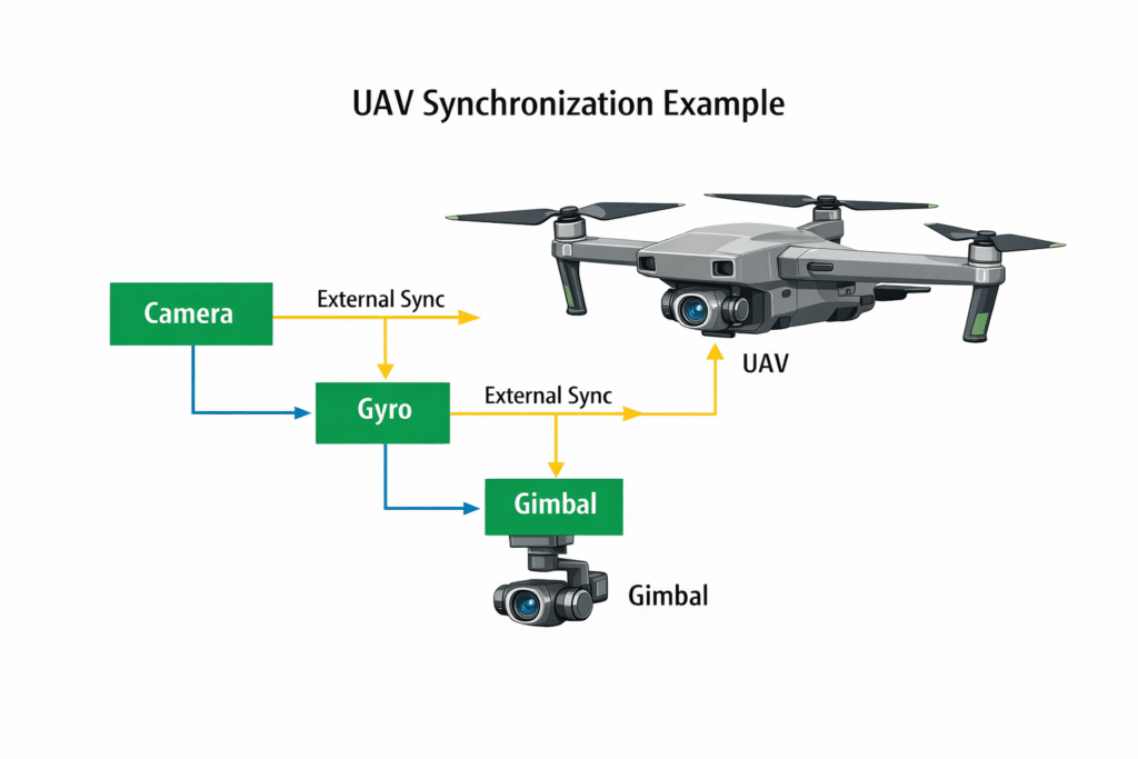
UAV system diagram illustrating how the camera, gyro and gimbal are connected through External Sync. The synchronization signal ensures that each gyro measurement is taken exactly at the moment of camera frame capture, enabling precise image stabilization and real-time navigation.
How timing jitter creates navigation drift
Assume a system sampling at 1000 Hz, meaning one sample every 1 millisecond.
If timing jitter is 100 microseconds, this represents a 10 percent error in sampling time.
At an angular rate of 300 degrees per second, this timing error produces an instantaneous angular error of:
0.03 degrees per sample
When this error is integrated over time, it accumulates into significant drift.
External Sync eliminates this problem because the sampling instant is defined in hardware, not by software timing.
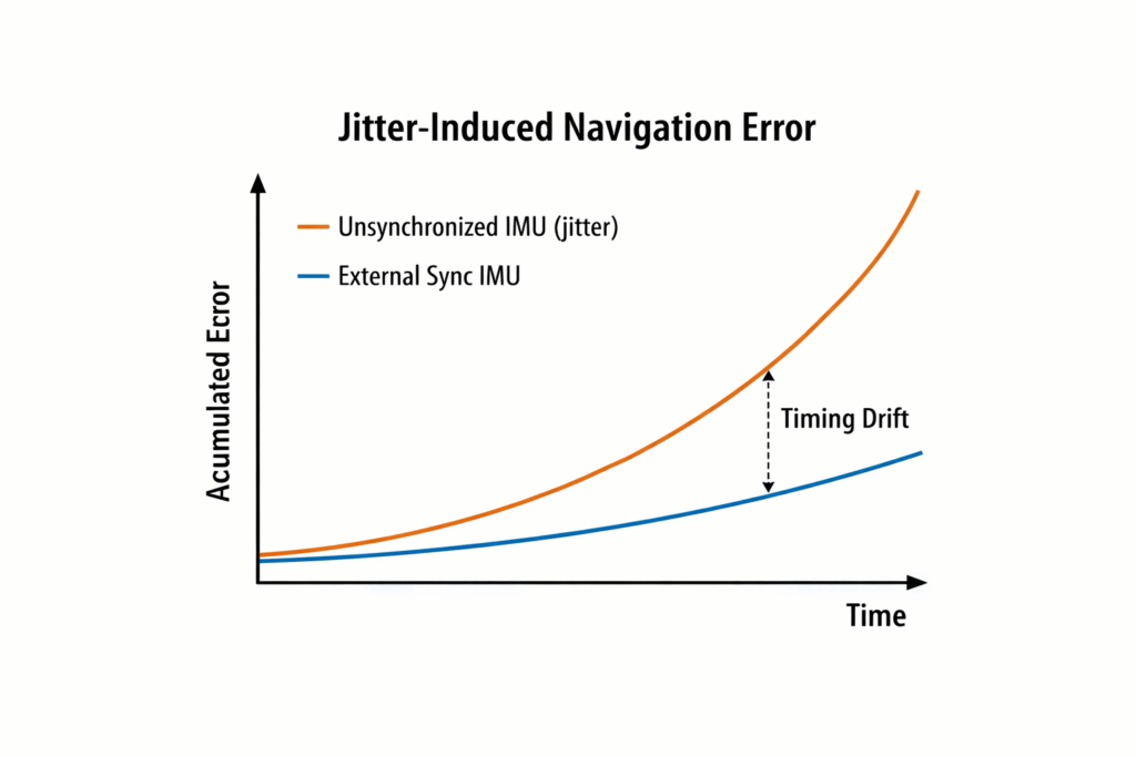
Graph illustrating how sampling-time jitter causes navigation error to accumulate over time. The upper curve represents an IMU without External Sync, where timing instability produces growing drift, while the lower curve represents an IMU with External Sync, maintaining small and stable error over time.
What to look for in a gyro datasheet
A gyro intended for synchronized systems should provide:
-
True hardware-based External Sync
-
Sync rates of several kilohertz or higher
-
Low and deterministic digital latency
-
Bandwidth matched to the sampling rate
-
A high-speed data interface
Without these capabilities, the theoretical accuracy of the gyro cannot be translated into real system performance.
How Amironic delivers External Sync gyros
Amironic supplies the G300D SX2 series from Gladiator Technologies with:
-
External Sync up to 8 kHz in standard configuration
-
External Sync up to 10 kHz with VELOX Plus
-
Ultra-low digital latency on the order of tens of microseconds
-
Bandwidth up to several hundred hertz
-
Extremely high data rates
This enables:
-
Precise alignment with cameras
-
Synchronization with radar and LiDAR
-
True navigation-grade INS performance, not just sensing
This is the difference between an industrial MEMS gyro and a MEMS device engineered for real navigation and stabilization systems.
Frequently Asked Questions (FAQ)
What is External Sync in a gyro?
External Sync is a hardware trigger input that forces the gyro to take a measurement exactly when an external pulse arrives.
Instead of sampling based on its internal clock, the G300D samples according to the system time.
Why is External Sync better than SPI or RS422 timing?
SPI and RS422 only determine when the data is read.
They do not control when the measurement was actually taken inside the sensor.
External Sync controls the sampling moment itself, at the ADC level.
Is software timestamping sufficient?
No. Timestamping only indicates when the data arrived at the CPU, not when the measurement was made.
Internal processing, filtering and serial transmission introduce variable delay (jitter).
How does timing error create drift?
Angular rate must be integrated over time.
If the time associated with each sample is wrong, the computed angle is wrong and the error accumulates.
Is External Sync required when using a camera?
Yes. Every camera frame is captured at a precise moment.
To know the platform orientation at that moment, the gyro must measure at the same time.
Is External Sync important for gimbals and UAVs?
Yes. Fast control systems require time-aligned measurements.
Without synchronization, oscillations, overshoot and instability occur.
Does the G300D provide true hardware triggering?
Yes. The G300D includes dedicated External Sync inputs (single-ended or differential) that directly trigger the measurement.
Can the G300D operate in free-running mode as well?
Yes. The G300D supports both free-running sampling and externally synchronized sampling.
What is the maximum synchronization rate?
Up to 8 kHz in standard mode and up to 10 kHz with VELOX Plus.
What happens if External Sync is not used?
The gyro runs on its internal clock and the system must estimate when each measurement occurred.
This severely limits navigation and stabilization accuracy.
Code Examples - External Sync with G300D
The G300D is designed to operate as a hardware-synchronized inertial sensor, where the system controls exactly when each measurement occurs.
The basic operating model is:
-
The system generates a synchronization pulse
-
The pulse triggers a new inertial measurement inside the G300D
-
The G300D transmits the resulting data frame over RS422/485
-
The processor reads already-synchronized data
The system never guesses when the measurement happened – it controls it.
Typical timing flow
The key point is that sampling happens at the External Sync edge, not when the CPU reads the data.
Pseudo-code: Triggered operation
This is a conceptual example of how a system using External Sync operates:
The timing reference is the external trigger, not the software loop.
Why this is superior to polling
Polling-based IMU systems look like this:
This only timestamps when the data was received, not when it was measured.
With External Sync:
The measurement time is known, fixed and controlled by the system.
Multi-sensor synchronization
In a typical EO/IR or UAV system:
This allows:
-
Frame-accurate stabilization
-
Pixel-accurate geo-referencing
-
Stable sensor fusion
All based on real sampling time, not guessed timestamps.
Integration Notes - Using G300D in Real Systems
Power Supply
The G300D operates from a single 5 V supply.
Because it is a precision inertial sensor, power quality directly affects performance.
Recommended practices:
-
Use a dedicated low-noise regulator
-
Place decoupling capacitors close to the IMU connector
-
Keep ground impedance low and return paths short
A clean power rail ensures low noise and stable bias.
RS422 / RS485 Data Interface
The G300D uses a differential serial interface (RS422 or RS485).
This provides:
-
High noise immunity
-
Long cable capability
-
Robust operation in industrial and airborne environments
The interface supports very high data rates, allowing full bandwidth and high sync rates without data loss.
External Sync Input
The External Sync input is the most critical signal in the system.
The G300D supports:
-
Single-ended sync (TTL level)
-
Differential sync (for high-noise or long-cable systems)
The sync signal should:
-
Have fast rising edges
-
Be generated from the same clock domain as the camera, FPGA or master controller
-
Be free of jitter
This signal defines the exact moment of inertial measurement.
System Clocking
In multi-sensor platforms, all timing should be derived from a common clock:
-
Camera
-
FPGA
-
GNSS
-
G300D
External Sync aligns the inertial sampling to this system clock, enabling true time correlation across all sensors.
Filter and Bandwidth Configuration
The G300D allows configuration of:
-
Output data rate
-
Bandwidth
-
Digital filtering
These must be matched to:
-
Vehicle dynamics
-
Control-loop speed
-
Sensor fusion rate
Higher bandwidth captures fast motion, while lower bandwidth improves noise and stability.
System Validation
A properly synchronized system will exhibit:
-
Stable attitude estimates
-
Smooth gimbal motion
-
Low drift
-
Consistent sensor fusion
Validation should include checking:
-
Sync pulse stability
-
IMU response to every trigger
-
Time alignment between IMU, camera and GNSS
When External Sync is correctly implemented, the inertial system behaves as a single coherent time-based instrument.
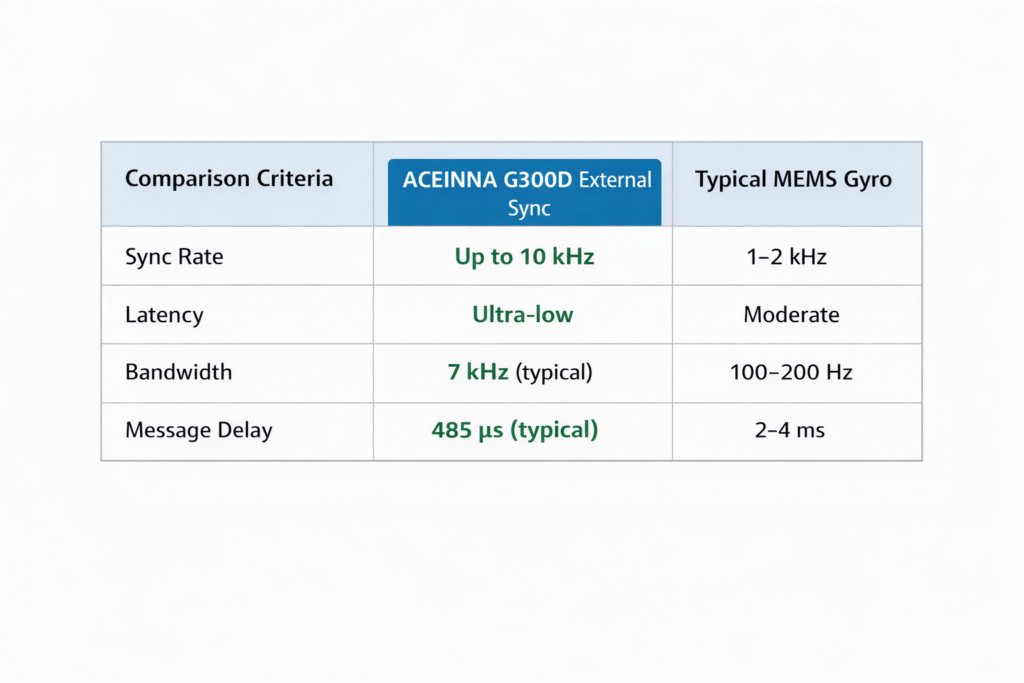
G300D vs Typical MEMS Gyro
G300D vs Typical MEMS Gyro
Most MEMS gyros look similar on datasheets, but they are built for very different system-level purposes.
This comparison shows why G300D belongs to the navigation and stabilization class, not to the general-purpose MEMS category.
| Feature | G300D External Sync Gyro | Typical MEMS Gyro |
|---|---|---|
| External Sync input | Yes, dedicated hardware trigger | No, free-running only |
| Control of sampling instant | System-controlled via sync pulse | Internal clock only |
| Sync rate | Up to 8 kHz (10 kHz with VELOX Plus) | Not supported |
| Sampling jitter | Deterministic, hardware-defined | Variable and uncontrolled |
| Digital latency | Low and fixed | Undefined or variable |
| Bandwidth | Hundreds of Hz | Usually limited |
| Data rate | High-speed RS422/RS485 | Typically low-speed SPI or UART |
| Multi-sensor alignment | True time-aligned | Estimated by software |
| Suitability for UAV and gimbal | Designed for it | Marginal |
| Suitability for INS | Navigation-grade | Not suitable |
Why this matters
A typical MEMS gyro provides angular rate data that is approximately correct in time.
The G300D provides angular rate data that is measured exactly when the system needs it.
That is the difference between a sensor and a navigation-grade inertial instrument.
Performance Metrics Explained - What the numbers really mean
Gyro datasheets list parameters such as ARW, bias, bandwidth and latency.
Without system context, these numbers do not explain how well a platform will actually perform.
This section shows how the G300D performance metrics translate into real system behavior.
Angle Random Walk (ARW)
ARW describes short-term noise in the angular rate measurement.
Low ARW means:
-
Less jitter in attitude
-
Smoother gimbal motion
-
Cleaner stabilization
-
More stable sensor fusion
The G300D provides extremely low ARW, but this advantage only becomes usable when measurements are time-aligned using External Sync.
Bias Stability
Bias is the constant offset in gyro output.
Bias stability determines how much that offset changes over time.
High bias stability means:
-
Low long-term drift
-
Better dead-reckoning
-
Reduced dependence on GNSS corrections
Without External Sync, even a stable bias becomes distorted by timing error.
Bandwidth
Bandwidth determines how fast the gyro can respond to motion.
High bandwidth is required for:
-
UAV maneuvering
-
Gimbal control
-
Vehicle dynamics
The G300D provides bandwidth in the hundreds of hertz, allowing fast motion to be measured without phase delay when synchronized.
Digital Latency
Digital latency is the time between sampling and data output.
Low, fixed latency is critical for:
-
Control loops
-
Sensor fusion
-
Predictable system response
The G300D is designed with very low and deterministic latency, allowing real-time operation when combined with External Sync.
Sync Rate
The sync rate determines how often the gyro can be triggered.
With External Sync up to 10 kHz, the G300D can:
-
Align with high-speed cameras
-
Track rapid vehicle dynamics
-
Avoid interpolation errors
This makes it suitable for precision inertial systems rather than basic motion sensing.
Bottom line
Noise, bias and bandwidth define the theoretical quality of a gyro.
External Sync and timing define whether that quality can be used by the system.
The G300D is designed to deliver both.
Applications – Where External Sync and G300D make the difference
The G300D is designed for platforms where timing accuracy, stability and sensor fusion directly determine mission success.
UAV and ISR Platforms
In UAVs, every camera frame, GNSS update and inertial measurement must be aligned in time.
External Sync allows the G300D to sample at the exact moment each image is captured, enabling:
-
Precise geo-referencing
-
Stable video stabilization
-
Accurate attitude estimation
-
Reliable navigation during GNSS dropouts
This is essential for ISR, mapping and targeting systems.
EO/IR and Imaging Payloads
Electro-optical and infrared payloads rely on tight alignment between optics and inertial sensors.
With External Sync, the G300D ensures that each frame is associated with the correct platform orientation, allowing:
-
Pixel-accurate stabilization
-
Target tracking
-
Image-based navigation
-
Multi-sensor correlation
Radar and LiDAR Systems
Radar and LiDAR operate on pulses and scans.
External Sync allows the G300D to be triggered by the same timing source, ensuring:
-
Accurate beam pointing
-
Motion compensation
-
Precise mapping
-
Stable target tracking
Without time-aligned inertial data, radar and LiDAR performance is fundamentally limited.
Robotics and Autonomous Systems
Autonomous vehicles and robotic platforms depend on fast, synchronized sensor fusion.
The G300D provides:
-
Deterministic timing
-
Low-latency inertial data
-
High bandwidth motion tracking
This enables stable localization, control and navigation in dynamic environments.
Why this matters
In all of these applications, External Sync turns inertial data from a rough estimate into a precise time-based reference.
The G300D provides the timing integrity required for modern autonomous and sensing platforms.