flagעברית
flagEnglish
3 Rabinovich St., Petah-Tikva, Israel
+972 3 9047744
office@amironic.co.il
Facebook
Twitter
LinkedIn
YouTube
  • Products
    • MEMS Inertial
      • MEMS Gyroscopes
      • Inertial Measurement Units
      • MEMS Accelerometers
      • Inertial Navigation
      • AHRS
    • Circuit Breakers
      • Airpax Circuit Breakers
      • Electronic Circuit Breakers
      • Aircraft Circuit Breakers
      • Thermal Circuit Breakers
      • Sealing Solutions & Guards
    • Footswitches
      • Pedals & Bellows
      • USB
      • Air Switches
      • Medical
      • Modular Bases System
      • Industrial
      • Foot Potentiometers
      • Wireless
    • Mechanical & Transmissions
      • Gears
      • Sealing Solutions
      • Gearboxes
      • Couplings
      • Shafts & Bearings
      • Fasteners
      • Mechanical & Springs
      • Linear Motion
      • Anti-Vibration
    • Sensors
      • Thermostats
      • Temperature
      • Position
      • Pressure
      • Speed
      • Level Sensor
      • Load Cells
      • Flex Sensors
      • Membrane Potentiometer
    • Motors
      • Geared DC
      • Brushless DC
      • Step Motors with Gearbox
      • Torque Motors & Brushless Servo
      • DC Motors
    • Electronics
      • Xenon & IR Lamps
      • Counters & Meters
      • Microelectronics Packaging
      • Waterproof Switches
      • Micro Switches
    • Hand Control
      • Operator Controls (JOYSTICK)
      • Electrical
      • Pneumatic (Medical)
      • USB Hand Control
      • Air Push Button
      • Pressure Switch
      • IR Switch
    • Power Solutions
      • Rugged & Military Power Supply
      • Input Power Protection
      • Sealed Military Power Adaptor
      • Triple Output Military Power Supply Series – up to 250 W
    • Materials
      • Molybdenum and Advanced Alloys (TZM, MOLA, HCT)
      • Tungsten (Wolfram) and Advanced Alloys – High-Performance Materials for Extreme Conditions
      • Materials for Gears
  • Shop
  • Companies
  • About Amironic
  • News
  • Contact
Product was added to your cart

Cart

waze

Industrial Footswitches – How to Select the Right Footswitch for Your Application

Footswitches02/11/2026amironicLTD

1. Introduction – A Footswitch Is Part of the Machine’s Control Interface

Industrial footswitches are used to operate and control machinery, production equipment, and automation systems. They allow operators to activate specific functions using their feet while keeping both hands free for other tasks.

Footswitches are commonly used in metalworking machinery, welding systems, packaging machines, assembly equipment, automated production lines, and applications requiring repetitive operation.

At first glance, a footswitch appears to be a simple component: a pedal, a mechanical mechanism, and an electrical contact. However, selecting the wrong footswitch can lead to operator fatigue, unintended activation, premature mechanical wear, and reduced production reliability.

Therefore, selecting an industrial footswitch should involve more than simply checking its physical dimensions or electrical ratings.

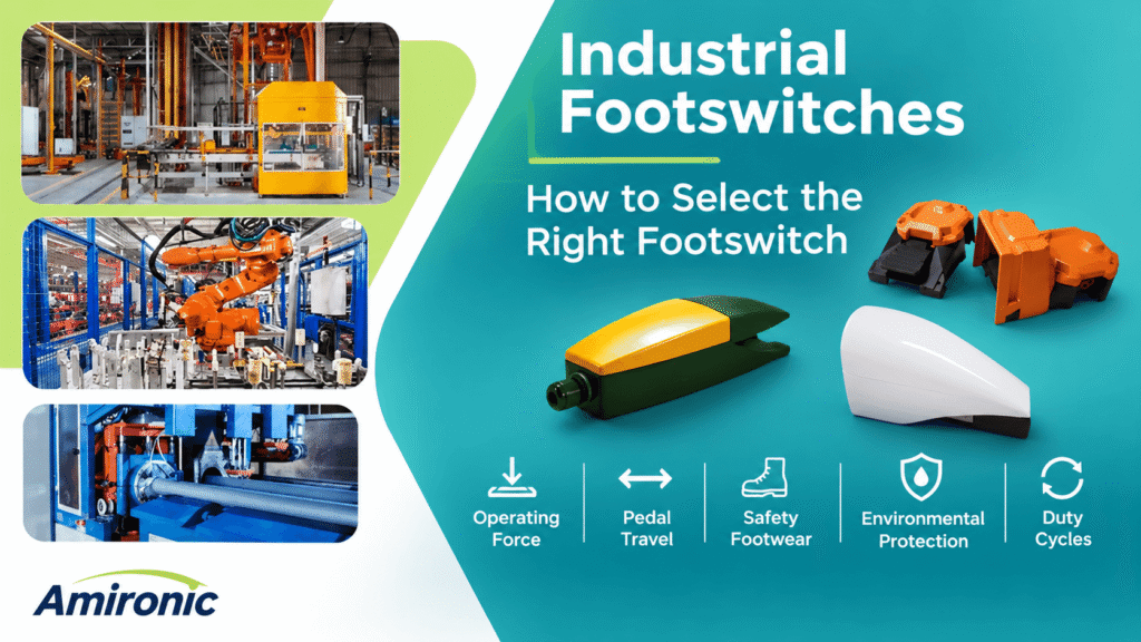
Several key engineering parameters should be considered:

  • Operating Force: The force required to press the pedal and actuate the switch.
  • Pedal Travel: The distance the pedal moves before switching occurs, as well as its total mechanical travel.
  • Safety Footwear Compatibility: The ability to operate the pedal comfortably and consistently while wearing safety shoes with rigid or wide soles.
  • Environmental Protection: Resistance to dust, moisture, water splashes, and other industrial operating conditions.
  • Operating Cycles: Matching the mechanical durability and electrical life of the switch to the expected frequency of operation.

HERGA Technology offers a wide range of industrial footswitches, from compact models for light-duty applications to heavy-duty footswitches featuring metal construction, multi-pedal configurations, and various environmental protection options.

In this article, we examine the key engineering considerations when selecting an industrial footswitch, explain how they affect operator comfort, operational safety, and product service life, and provide practical rules of thumb to help engineers choose the right solution for their applications.


2. Operating Force – Balancing Comfort and Control

Operating force is one of the most important parameters when selecting an industrial footswitch.

It refers to the force required to move the pedal mechanism to the electrical switching point. This force depends on the pedal design, spring mechanism, point of applied pressure, and characteristics of the internal switch.

Low Operating Force – When Is It Suitable?

A low operating force allows the footswitch to be activated with relatively little effort.

This may be particularly suitable for applications requiring frequent operation throughout a work shift, such as:

  • Manual assembly stations.
  • Test equipment operation.
  • Machines requiring short, repetitive activation cycles.
  • Workstations where the operator remains seated for most of the working day.

The main advantage is reduced effort during each activation.

However, an operating force that is too low may increase the risk of unintended activation, particularly when an operator rests a foot on the pedal between operations.

High Operating Force – When Is It Preferable?

A higher operating force requires a more deliberate and noticeable pedal press.

This may be useful in applications where it is important to distinguish between resting a foot on the switch and intentionally activating it.

For example, in industrial environments where operators wear heavy safety footwear, it is important to evaluate whether the weight of the shoe and a resting foot could unintentionally activate the switch.

However, increasing the operating force is not a substitute for mechanical protection against accidental activation or appropriate machine safety design.

Engineering Rule of Thumb

The higher the operating frequency, the more important it becomes to evaluate the cumulative physical effort required from the operator.

Conversely, where unintended activation could have significant consequences, greater emphasis should be placed on mechanical guarding, pedal positioning, and control system design.

Important: There is no universal operating force suitable for every machine. Always consult the manufacturer’s specifications for the exact footswitch model and evaluate its operating characteristics under actual working conditions.
3. Pedal Travel – Why Shorter Travel Is Not Always Better

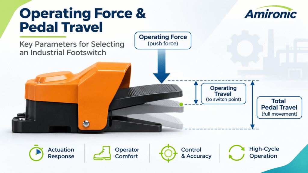
Pedal travel refers to the distance a footswitch pedal moves when pressed, from its resting position to the actuation point or the end of its mechanical travel.

Pedal travel directly influences the feel of operation, actuation response, operator comfort, and the ability to control machinery consistently.

Contrary to common assumptions, shorter pedal travel is not necessarily better than longer travel. The optimal choice depends on the type of operation, activation frequency, and working environment.

3.1 Operating Travel vs. Total Pedal Travel

When evaluating an industrial footswitch, it is important to distinguish between two parameters:

Operating Travel

The distance the pedal moves before the electrical contact changes state.

This is one of the factors that determines how responsive the footswitch feels to the operator.

Total Pedal Travel

The total distance the pedal can move before reaching its mechanical stop.

In some footswitch designs, the pedal can continue moving after electrical switching has occurred. This additional movement is commonly referred to as Overtravel.

This distinction is important because two footswitches with similar total travel distances may provide very different operating characteristics if their switching points occur at different positions along the pedal’s movement.

3.2 Short Pedal Travel – Advantages and Limitations

A footswitch with short pedal travel requires relatively little foot movement to activate the switch.

This configuration may be suitable for applications involving frequent, repetitive operations, such as:

  • Testing and quality control stations.
  • Assembly machinery.
  • Equipment requiring short operating cycles.
  • Systems requiring a quick response to operator commands.

Main advantage: Reduced foot movement, which may help minimize physical effort during repetitive operations.

However, extremely short pedal travel can make it more difficult for operators to distinguish between the resting and activated positions, particularly when wearing safety footwear with rigid soles.

It is also important to remember that shorter pedal travel does not necessarily mean faster electrical response. The overall response time of the control system also depends on the switching mechanism, controller, and controlled process.

3.3 Long Pedal Travel – Control and Tactile Feedback

Longer pedal travel allows greater foot movement during activation.

In certain applications, this additional movement can provide a clearer sense of control and make the actuation point easier to recognize.

Longer pedal travel may be suitable when:

  • Operators wear heavy industrial safety footwear.
  • A clear distinction between resting and activated positions is required.
  • Activation frequency is relatively moderate.
  • Operators prefer more noticeable mechanical feedback.

However, excessive pedal travel may increase the movement required from the ankle and foot, particularly when the switch is activated hundreds or thousands of times during a work shift.

3.4 The Relationship Between Operating Force and Pedal Travel

Operating force and pedal travel should not be evaluated independently when considering operator comfort and usability.

A combination of high operating force and long pedal travel may result in demanding operation, particularly when frequent activation is required.

Conversely, low operating force combined with short pedal travel may provide easy, rapid activation but requires careful consideration of the risk of accidental operation.

Therefore, both parameters should be evaluated together rather than selecting a footswitch based on either characteristic alone.

3.5 Rules of Thumb for Selecting Pedal Travel

Application Requirement Engineering Recommendation
Frequent activation throughout a shift Consider relatively short travel and ergonomic comfort
Operators wearing rigid safety footwear Ensure the actuation point can be clearly recognized
Need for clear activation feedback Evaluate pedal travel and mechanical feedback
Prolonged standing operation Assess foot angle and required movement
Risk of unintended activation Consider mechanical guarding and appropriate safety design
Continuous operation with the pedal held down Evaluate comfort during prolonged pedal depression

3.6 How to Evaluate Pedal Travel in Practice

Before selecting a footswitch for an industrial application, it is advisable to conduct practical testing under conditions that closely resemble the actual working environment.

Testing should be performed using the safety footwear normally worn by operators, in standing or seated positions as appropriate for the workstation.

The evaluation should determine whether the operator can consistently recognize the actuation point, whether excessive ankle movement is required, and whether the pedal reliably returns to its resting position after release.

For applications involving high activation frequencies, extended testing that simulates the expected operating cycle is also recommended.

Engineering Takeaway: The most suitable industrial footswitch is not necessarily the one with the shortest pedal travel. It is the one that provides the right balance of movement, operating force, mechanical feedback, and long-term operator comfort.

4. Safety Footwear – Matching the Pedal to the Operator

4. Safety Footwear – Matching the Pedal to the Operator

In industrial manufacturing environments, operators often wear safety footwear with protective toe caps, rigid soles, and sometimes relatively wide designs.

These characteristics affect how a footswitch is operated and should therefore be considered during the machine design stage.

4.1 How Safety Footwear Affects Pedal Operation

Rigid soles may reduce the tactile feedback operators receive when pressing a footswitch.

As a result, a footswitch with extremely short pedal travel or an indistinct actuation point may be less comfortable to operate.

In addition, wide safety footwear may make it difficult to position the foot inside a guarded footswitch, particularly when the opening is narrow.

When selecting an industrial footswitch, consider the following:

  • Is the pedal wide enough to accommodate the operator’s safety footwear?
  • Can the switch be operated without excessive changes in foot position?
  • Is the actuation point clearly noticeable through a rigid sole?
  • Is there sufficient clearance between the safety shoe and the protective guard?
  • Can the operator release the pedal quickly and comfortably?

4.2 Footswitch Guards – When Are They Necessary?

A footswitch guard is a mechanical structure installed around or above the pedal to help reduce the risk of accidental activation caused by unintended contact.

Such guards may be particularly useful in industrial environments where personnel, equipment, or materials frequently move near the operating station.

However, the guard must provide sufficient clearance for the operator’s footwear and must not interfere with normal activation or rapid pedal release.

HERGA Example: The HERGA 6256 Heavy Duty series offers protective guard options and configurations designed to accommodate industrial safety footwear.

It is important to emphasize that a protective guard alone does not constitute a complete machine safety system and does not replace a proper risk assessment or other required safety measures.

4.3 Rules of Thumb for Safety Footwear Compatibility

Working Condition Engineering Recommendation
Wide safety footwear Select a pedal and guard with sufficient clearance
Rigid shoe soles Evaluate mechanical feedback and the actuation point
Prolonged standing operation Assess foot angle and cumulative operating effort
Crowded industrial environments Consider protective guarding and suitable footswitch positioning
Multiple adjacent footswitches Ensure clear differentiation between pedals

Rule of Thumb: Always evaluate a footswitch using the actual safety footwear worn by operators, rather than relying solely on testing with ordinary shoes under laboratory conditions.


5. Environmental Protection – Matching the Footswitch to Industrial Conditions

Industrial footswitches may be exposed to dust, moisture, liquid splashes, oils, cleaning agents, and mechanical impacts.

Therefore, selecting the right footswitch requires consideration not only of its operating characteristics but also of the environmental conditions it will encounter.

5.1 IP Ratings – What Do They Really Mean?

Ingress Protection (IP) ratings, defined by IEC 60529, classify the degree of protection provided by an enclosure against the ingress of solid objects and water.

For example:

IP Rating Protection Level
IPX2 Protection against dripping water under specified test conditions
IPX7 Protection against the effects of temporary immersion in water under specified conditions
IP67 Dust-tight protection and protection against the effects of temporary immersion in water
IP68 Dust-tight protection and protection against immersion under conditions specified by the manufacturer

It is important to distinguish between IPX7 and IP67.

The letter X indicates that no protection rating against solid objects is specified in that designation. It does not necessarily mean that the product offers no protection against solids.

Additionally, an IP rating does not automatically indicate resistance to oils, chemicals, high-pressure cleaning, or mechanical impacts.

5.2 Selecting Environmental Protection for the Application

Relatively Clean and Dry Manufacturing Environments

A footswitch with a basic level of environmental protection may be suitable, depending on the actual exposure risks.

Dusty Environments or Areas with Metal Chips

Evaluate protection against particle ingress, suitable mechanical construction, and the ability to clean the pedal and its mechanism.

Wet Environments or Areas Exposed to Water Splashes

Select an appropriate IP rating and verify cable entry sealing and compatibility with cleaning procedures.

Environments Exposed to Oils and Coolants

The chemical compatibility of the enclosure materials, seals, and cables must be evaluated separately.

5.3 HERGA 6256 Heavy Duty – An Example

The HERGA 6256 series is designed for demanding industrial applications and offers modular construction with different environmental protection options.

According to HERGA specifications, IPX2 configurations and IP67 options are available, depending on the selected version.

This means that not every footswitch in the 6256 family automatically provides the same level of environmental protection.

The IP rating of the exact part number should always be verified, including accessories, cable connections, and installation configuration.

Rule of Thumb: Select the required environmental protection level based on the conditions expected throughout the machine’s service life, not just those present on the installation day.


6. Operating Cycles – How Long Will an Industrial Footswitch Last?

In industrial applications, a footswitch may be activated tens, hundreds, or even thousands of times per day.

Therefore, the expected number of operating cycles is a key factor in selecting the appropriate footswitch.

6.1 Mechanical Life vs. Electrical Life

It is important to distinguish between two different specifications.

Mechanical Life

The number of operating cycles the mechanical mechanism is designed to withstand under specified test conditions.

Electrical Life

The number of switching operations the electrical contacts are expected to perform under defined electrical load conditions.

These two values are not necessarily identical.

A footswitch may remain mechanically functional even after its electrical contacts have experienced significant wear due to repeated switching under load.

6.2 How to Calculate Operating Cycles

Consider a machine activated 20 times per minute, operating for 6 hours per day, 250 working days per year.

The estimated annual number of activations is:

20 × 60 × 6 × 250 = 1,800,000 operating cycles per year.

This means that a footswitch with a nominal mechanical life of one million cycles could reach that number in less than one year of operation.

This calculation is provided for illustration only. Actual service life depends on operating conditions, electrical loads, environmental exposure, and manufacturer specifications.

6.3 HERGA 6256 – Mechanical Life Considerations

According to HERGA specifications, the mechanical life of footswitches within the 6256 family depends on the selected version and configuration.

For example, a mechanical life of one million operating cycles is specified for the HERGA 6256 Heavy Duty Multipedal configuration.

Other configurations may have different mechanical life ratings.

For high-cycle applications, engineers should verify the exact part number’s specifications, including mechanical life and electrical life under the intended load conditions.

6.4 How Electrical Loads Affect Service Life

Electrical life is influenced by the type of load being switched.

Switching a digital PLC input is not necessarily equivalent to directly switching a solenoid, motor, or other inductive load.

Inductive loads may generate voltage transients and electrical arcing when the circuit is opened, potentially accelerating contact wear.

Therefore, the electrical rating should be evaluated according to the actual load type, voltage, and current.

Where necessary, an appropriate relay or control interface should be considered.

Rule of Thumb: Never select a footswitch based solely on its published cycle life. First calculate the expected annual number of activations and compare it with both the mechanical and electrical life specifications.

7. How to Select the Right HERGA Industrial Footswitch

After evaluating operating force, pedal travel, safety footwear compatibility, environmental protection, and operating cycles, engineers can narrow down their selection to the most suitable footswitch families.

HERGA Technology offers several industrial footswitch ranges designed for different operating requirements.

Product Family Key Features Typical Applications
HERGA 6219 Light Industrial Compact construction, IPX7 protection, extended operating temperature range OEM equipment, testing and control systems
HERGA 6289 General Purpose Versatile metal construction, multiple configuration options Industrial machinery and workstations
HERGA 6256 Heavy Duty Modular construction, protective guard options, multi-pedal configurations, optional IP67 protection Production machinery and demanding industrial applications

This table provides general selection guidance only.

The final choice should be based on the exact part number and its operating force, pedal travel, contact configuration, electrical ratings, and environmental specifications.

Seven Questions to Ask Before Selecting an Industrial Footswitch

  1. How many times per day will the operator activate the pedal?
  2. Will the footswitch be operated while standing or sitting?
  3. Will operators be wearing industrial safety footwear?
  4. Is there a risk of unintended activation?
  5. Will the footswitch be exposed to water, dust, oils, or cleaning agents?
  6. Will the switch control a PLC input or directly switch an electrical load?
  7. Is a single pedal sufficient, or is a multi-pedal configuration required?

Answering these questions helps identify the most appropriate footswitch family before selecting the exact mechanical and electrical configuration.


8. Case Study – Selecting a Footswitch for an Industrial Packaging Machine

Illustrative engineering case study demonstrating the selection process. This is not a documented customer installation.

The Challenge

A packaging machine manufacturer is designing a workstation where the operator must hold a product with both hands while initiating a machine cycle using a foot pedal.

The machine operates across two shifts, and operators wear industrial safety footwear.

The footswitch is positioned near the machine in an environment where dust and packaging debris may accumulate.

The application requires:

  • Comfortable, repetitive operation throughout the work shift.
  • Compatibility with industrial safety footwear.
  • Reduced risk of accidental activation.
  • Long-term mechanical durability.
  • Straightforward replacement during maintenance.
  • Reliable connection to the machine’s control system.

Engineering Analysis

Step 1 – Evaluating Operating Frequency

Assume the machine performs 8 operating cycles per minute, with 6 effective operating hours per day and 250 working days per year.

The estimated annual number of activations is:

8 × 60 × 6 × 250 = 720,000 operating cycles per year.

This calculation provides a starting point for evaluating the required mechanical and electrical life of the footswitch.

Over three years, the application would accumulate approximately 2.16 million operating cycles, assuming the same operating conditions.

Therefore, the selected footswitch must be evaluated against the intended service interval and maintenance requirements, not merely its first year of operation.

Step 2 – Evaluating Ergonomics

Because operators wear safety footwear, pedal width, guard clearance, operating force, and pedal travel must all be considered.

The footswitch should provide consistent activation without requiring excessive ankle movement or awkward foot positioning.

Step 3 – Reducing Accidental Activation

A footswitch with a suitable protective guard should be considered to help reduce the likelihood of unintended operation.

The machine’s overall safety design must also be evaluated through an appropriate risk assessment.

Step 4 – Environmental Protection

Dust and packaging debris may accumulate around the operating station.

The required ingress protection rating should therefore be selected based on actual exposure conditions and cleaning procedures.

Step 5 – Electrical Interface

If the footswitch is connected to a PLC input, the electrical characteristics and contact configuration must be compatible with the control system.

The system’s response to cable disconnection, contact failure, or other faults should also be considered.

Potential Solution – HERGA 6256 Heavy Duty

The HERGA 6256 Heavy Duty series is a potential candidate for this application due to its industrial construction, protective guard options, compatibility with safety footwear, and available configurations.

However, suitability must be confirmed against the exact part number’s specifications.

For example, a mechanical life of one million cycles is specified for the 6256 Heavy Duty Multipedal configuration, while other versions may have different ratings.

With an estimated 720,000 activations per year, a one-million-cycle rating would be reached after approximately 1.4 years of operation.

Consequently, the final selection should consider the intended maintenance interval, replacement strategy, and both mechanical and electrical life requirements.

The Engineering Takeaway

Selecting the right industrial footswitch involves much more than choosing a mechanically robust pedal.

A reliable solution requires a balanced evaluation of operating frequency, ergonomics, accidental activation risks, environmental exposure, electrical compatibility, and maintenance requirements.

The HERGA 6256 family provides several configuration options that can be evaluated against these requirements, allowing machine designers to select a solution suited to their specific application.

9. Conclusion – Selecting an Industrial Footswitch Is an Engineering Decision

An industrial footswitch may be a relatively small component within a machine, but its impact on operator comfort, operational reliability, and machine safety can be significant.

Selecting the right footswitch requires evaluating five key parameters:

  • Operating Force: Balancing comfortable activation with the need to reduce unintended operation.
  • Pedal Travel: Matching pedal movement and tactile feedback to the application and operating frequency.
  • Safety Footwear Compatibility: Ensuring that the pedal, actuation point, and protective guard accommodate the operator’s footwear.
  • Environmental Protection: Selecting appropriate IP ratings and materials for the actual industrial environment.
  • Operating Cycles: Matching mechanical and electrical life to the expected activation frequency and service requirements.

HERGA Technology offers a comprehensive range of industrial footswitches, including Light Industrial, General Purpose, and Heavy Duty models, with various construction materials, connection options, protective guards, and multi-pedal configurations.

Amironic Ltd., HERGA Technology’s representative in Israel, assists engineers and machine manufacturers in selecting industrial footswitches based on their technical requirements, environmental conditions, and control system specifications.

For additional information, explore the HERGA Industrial Footswitches product range or contact Amironic for assistance in selecting the most suitable footswitch for your application.


10. Frequently Asked Questions (FAQs)

What Is the Difference Between a Standard Industrial Footswitch and a Heavy Duty Footswitch?

A Heavy Duty footswitch is generally designed for more demanding industrial environments and typically features robust mechanical construction and additional protection options, depending on the model.

However, the Heavy Duty designation does not automatically guarantee a higher IP rating, a specific operating force, or a longer service life.

Always verify the specifications of the exact model.

Is Short Pedal Travel Better for Fast, Repetitive Operation?

Not necessarily.

Short pedal travel may reduce the amount of foot movement required, making it suitable for frequent activation.

However, the actuation point should remain clearly recognizable, and the risk of accidental activation must be evaluated.

The ideal pedal travel depends on operating frequency, footwear, ergonomics, and the application.

Can Industrial Footswitches Be Operated While Wearing Safety Footwear?

Yes. Many industrial footswitches are designed for operation with safety footwear.

However, pedal dimensions, protective guard clearance, operating force, and mechanical feedback should be evaluated.

The HERGA 6256 Heavy Duty series includes configurations suitable for operation with industrial safety footwear.

Is an IP67 Footswitch Suitable for Every Wet Industrial Environment?

No.

IP67 indicates dust-tight protection and protection against the effects of temporary immersion in water under specified test conditions.

It does not automatically guarantee resistance to high-pressure water jets, cleaning chemicals, oils, or other industrial fluids.

The environmental requirements of the specific application must be evaluated separately.

How Many Operating Cycles Should an Industrial Footswitch Withstand?

The required operating life depends on activation frequency, expected machine service life, and maintenance requirements.

For example, a footswitch activated 10 times per minute for 6 hours per day and 250 days per year would experience:

10 × 60 × 6 × 250 = 900,000 operating cycles per year.

Engineers should compare the expected number of cycles with the manufacturer’s mechanical and electrical life specifications under the relevant operating conditions.

Can an Industrial Footswitch Be Connected Directly to a PLC?

In many applications, yes.

The footswitch contact configuration, voltage, current, and electrical characteristics must be compatible with the PLC input requirements.

The control system should also be designed to respond appropriately to faults such as cable disconnection or contact failure.

When Should a Footswitch with a Protective Guard Be Used?

A protective guard should be considered when there is a risk of unintended pedal activation, particularly in crowded work areas or near moving equipment.

The guard helps reduce accidental contact with the pedal.

However, a protective guard does not replace other machine safety measures required by the application’s risk assessment.

Can a Standard Industrial Footswitch Be Used to Operate Hazardous Machinery?

A footswitch may be incorporated into a properly designed machine control system, including machinery with potentially hazardous movements.

However, the machine must undergo an appropriate risk assessment, and the control system must meet the applicable safety requirements.

A standard industrial footswitch should not automatically be considered a safety-rated device or assumed suitable for safety functions such as emergency stopping or prevention of unexpected startup without appropriate design and validation.

Does HERGA Offer Multi-Pedal Industrial Footswitches?

Yes.

HERGA Technology offers multi-pedal configurations, including modular solutions within the 6256 Heavy Duty family.

These configurations can be useful for machines requiring foot-operated control of multiple functions.

The appropriate configuration should be selected based on the required number of functions, available space, operating sequence, and electrical interface.


11. Glossary of Terms – Industrial Footswitches

Industrial Footswitch

A foot-operated control device used to send an electrical switching command to machinery or a control system.

Operating Force

The force required to actuate the footswitch mechanism, typically expressed in newtons (N).

Pedal Travel

The distance the footswitch pedal moves during activation.

Operating Travel

The distance the pedal moves from its resting position to the point where the electrical contact changes state.

Overtravel

Additional pedal movement that may occur after the electrical switching point has been reached, up to the mechanical stop.

Mechanical Life

The number of operating cycles a mechanical mechanism is designed to withstand under specified test conditions.

Electrical Life

The expected number of electrical switching operations under defined load conditions.

Electrical life may vary depending on voltage, current, and load type.

Duty Cycle

A description of an operating pattern, including the duration of active and inactive periods.

Duty cycle should not be confused with the total accumulated number of operating cycles.

Ingress Protection (IP)

A classification system defined by IEC 60529 that indicates the degree of protection provided by an enclosure against the ingress of solid objects and water.

Footswitch Guard

A protective mechanical structure designed to help reduce the risk of accidental footswitch activation.

Normally Open (NO)

An electrical contact that remains open in its normal, unactuated state and closes when activated.

Normally Closed (NC)

An electrical contact that remains closed in its normal, unactuated state and opens when activated.

Momentary Action

A switching mechanism that returns to its normal state when the operator releases the pedal.

Maintained Action

A switching mechanism that retains its activated state after the operating force is removed, until a separate release or switching action occurs.

Multi-Pedal Footswitch

A foot-operated control assembly containing two or more pedals, allowing operators to control multiple machine functions.

PLC – Programmable Logic Controller

An industrial digital controller used to automate machinery, production processes, and other industrial control applications.

OEM – Original Equipment Manufacturer

A company that manufactures equipment or systems and integrates components into its products.

Tags: Herga

Related Articles

How Does an Air Switch Work? A Simple Guide

24/02/2025amironicLTD

The Role of Vacuum Switches in Fume Extraction Systems

25/02/2025amironicLTD

USB Footswitches – USB-C Now Available!

04/03/2025amironicLTD

Recent Posts

  • How Do Shock and Vibration Affect IMU Measurement Accuracy?
  • Industrial Footswitches – How to Select the Right Footswitch for Your Application
  • Open-Loop vs. Closed-Loop Accelerometers – Which Technology Is Right for Your Application?
  • Overtemperature Protection Up to 450°C – Advanced Thermal Solutions for Industrial Ovens and Equipment
  • SX2 vs. SX3 – The Future of Inertial Sensor Technology

Categories

  • Air Switch
  • Circuit Breakers
  • Elapsed Time Indicator
  • Feedthrough
  • Footswitches
  • Gears & Transmission
  • Hour Meters
  • Infra Red Switches
  • INFRARED LAMPS
  • Low Noise Inertial MEMS
  • Mechanics
  • MEMS Gyroscope
  • MEMS Inertial
  • Microelectronics
  • Motors
  • Position Sensors
  • Power Supply
  • Pressure Sensors
  • Pressure Switch
  • Sealing
  • Switches
  • Temperature Sensors
  • Tungsten and Molybdenum
  • Uncategorized
  • Vacuum Switches

Quick Contact

Fill out the form and our representatives will return to you

    Name (required)

    Email (required)

    Phone

    Message

    This site is protected by reCAPTCHA and the Google
    Privacy Policy and
    Terms of Service apply.

    Amironic Ltd.

    3 Rabinovich Street, Petah Tikva 4928144 , Israel. Tel: +972-3-9047744 E-mail: office@amironic.co.il
    Email
    Facebook
    Twitter
    LinkedIn
    YouTube
    Press on the ISO Certificate below for download
    ISO 9001:2015 Certification
    • MEMS Inertial
    • Circuit Breakers
    • Footswitches
    • Mechanical & Transmissions
    • Sensors
    • Motors
    • Electronics
    • Hand Control
    • Power Solutions

    News

    • How Do Shock and Vibration Affect IMU Measurement Accuracy?
    • Industrial Footswitches – How to Select the Right Footswitch for Your Application
    • Open-Loop vs. Closed-Loop Accelerometers – Which Technology Is Right for Your Application?
    • Overtemperature Protection Up to 450°C – Advanced Thermal Solutions for Industrial Ovens and Equipment
    • SX2 vs. SX3 – The Future of Inertial Sensor Technology
    About AmironicContactעברית
    © 2022 Amironic All rights reserved. All Trademarks are the property of their respective owners.
    • Increase Font
    • Decrease Font
    • Black & White
    • Inverse Colors
    • Highlight Links
    • Regular Font
    • Reset