flagעברית
flagEnglish
3 Rabinovich St., Petah-Tikva, Israel
+972 3 9047744
office@amironic.co.il
Facebook
Twitter
LinkedIn
YouTube
  • Products
    • MEMS Inertial
      • MEMS Gyroscopes
      • Inertial Measurement Units
      • MEMS Accelerometers
      • Inertial Navigation
      • AHRS
    • Circuit Breakers
      • Airpax Circuit Breakers
      • Electronic Circuit Breakers
      • Aircraft Circuit Breakers
      • Thermal Circuit Breakers
      • Sealing Solutions & Guards
    • Footswitches
      • Pedals & Bellows
      • USB
      • Air Switches
      • Medical
      • Modular Bases System
      • Industrial
      • Foot Potentiometers
      • Wireless
    • Mechanical & Transmissions
      • Gears
      • Sealing Solutions
      • Gearboxes
      • Couplings
      • Shafts & Bearings
      • Fasteners
      • Mechanical & Springs
      • Linear Motion
      • Anti-Vibration
    • Sensors
      • Thermostats
      • Temperature
      • Position
      • Pressure
      • Speed
      • Level Sensor
      • Load Cells
      • Flex Sensors
      • Membrane Potentiometer
    • Motors
      • Geared DC
      • Brushless DC
      • Step Motors with Gearbox
      • Torque Motors & Brushless Servo
      • DC Motors
    • Electronics
      • Xenon & IR Lamps
      • Counters & Meters
      • Microelectronics Packaging
      • Waterproof Switches
      • Micro Switches
    • Hand Control
      • Operator Controls (JOYSTICK)
      • Electrical
      • Pneumatic (Medical)
      • USB Hand Control
      • Air Push Button
      • Pressure Switch
      • IR Switch
    • Power Solutions
      • Rugged & Military Power Supply
      • Input Power Protection
      • Sealed Military Power Adaptor
      • Triple Output Military Power Supply Series – up to 250 W
    • Materials
      • Molybdenum and Advanced Alloys (TZM, MOLA, HCT)
      • Tungsten (Wolfram) and Advanced Alloys – High-Performance Materials for Extreme Conditions
      • Materials for Gears
  • Shop
  • Companies
  • About Amironic
  • News
  • Contact
Product was added to your cart

Cart

waze

Hook Terminal vs. Screw Terminal – Understanding Terminal Connections in AIRPAX Hydraulic Magnetic Circuit Breakers

Circuit Breakers08/11/2026amironicLTD

1. Introduction – Why Does Terminal Type Matter When Selecting a Hydraulic Magnetic Circuit Breaker?

When selecting a hydraulic magnetic circuit breaker for electrical circuit protection, engineers typically focus on parameters such as rated current, operating voltage, time-delay characteristics, interrupting capacity, and environmental resistance. However, another important factor can influence system design, installation, and maintenance: the terminal connection type.

Two terminal configurations available in hydraulic magnetic circuit breakers are Hook Terminal and Screw Terminal. Although both provide an electrical connection between the circuit breaker and the protected circuit, they differ in terminal construction, wire termination methods, assembly requirements, and maintenance considerations.

These differences become particularly important in military, aerospace, and industrial applications, where reliable circuit protection may be required under mechanical shock, vibration, temperature variations, and other demanding environmental conditions.

AIRPAX AP/UP Series – Sealed Hydraulic Magnetic Circuit Breakers

The AIRPAX AP/UP series from Sensata Technologies includes hydraulic magnetic circuit protectors that combine overcurrent protection with manual switching capabilities.

Unlike thermal circuit breakers, the hydraulic magnetic operating mechanism used in the AP series is designed to provide relatively consistent tripping characteristics across a wide range of ambient temperatures.

Key features of the AIRPAX AP series include:

  • Trip-Free Mechanism: Allows the circuit breaker to trip under overcurrent conditions even when the operating handle is held in the ON position.
  • Fully Sealed Construction: Helps protect the internal mechanism from environmental contaminants, in accordance with the manufacturer’s specifications.
  • Shock and Vibration Resistance: Designed and tested for mechanical shock and vibration under specified test conditions.
  • Multiple Time-Delay Options: Enables engineers to select tripping characteristics appropriate for different loads and inrush current requirements.
  • Single-Pole and Multi-Pole Configurations: The AP series includes single-pole, two-pole, and three-pole circuit breakers.
  • Military AP-MIL Versions: Selected configurations are manufactured and qualified in accordance with MIL-PRF-39019 and applicable military specification sheets.

The AIRPAX UP series uses a similar hydraulic magnetic operating principle but is designed for single-pole applications, with different regulatory approvals and recognition depending on the specific model.

For military procurement, it is important to distinguish between standard commercial AP/UP configurations and qualified military versions identified by M39019 part numbers. Similar electrical characteristics do not automatically indicate equivalent military qualification.

Case Study: AIRPAX AP112 vs. AP117

To illustrate the practical implications of terminal selection, consider two three-pole hydraulic magnetic circuit breakers from the AIRPAX AP series:

AIRPAX AP112 – Three-Pole Hook Terminal Circuit Breaker

The AP112 features heavy copper hook terminals, providing connection points for wire termination using an appropriate assembly method.

AIRPAX AP117 – Three-Pole Screw Terminal Circuit Breaker

The AP117 features screw terminals with an integrated terminal block, allowing electrical connections to be secured using the manufacturer’s specified fastening hardware and tightening torque.

Although both models belong to the same circuit breaker family, their differences extend beyond terminal geometry.

According to the manufacturer’s catalog, Screw Terminal configurations are available with Series Trip construction only, whereas Hook Terminal configurations support additional internal circuit arrangements, subject to the selected part number.

This distinction can influence component selection when a system requires specific tripping functions, auxiliary contacts, or specialized electrical configurations.

What Will This Guide Cover?

This technical guide examines the construction, advantages, and limitations of Hook Terminal and Screw Terminal connections in AIRPAX hydraulic magnetic circuit breakers.

It also explores:

  • The engineering differences between AIRPAX AP112 and AP117.
  • Wiring, installation, tightening torque, and maintenance considerations.
  • Auxiliary Switch options, including Pierced Pin and Cane Hook terminals.
  • Rated current, time-delay characteristics, and environmental requirements.
  • Military circuit breakers manufactured under MIL-PRF-39019, including the M39019 part number family.
  • Practical selection guidelines for new designs and replacement applications.

The objective is to help engineers and procurement professionals select the appropriate AIRPAX circuit breaker based on electrical performance, mechanical integration, environmental conditions, and applicable qualification requirements.
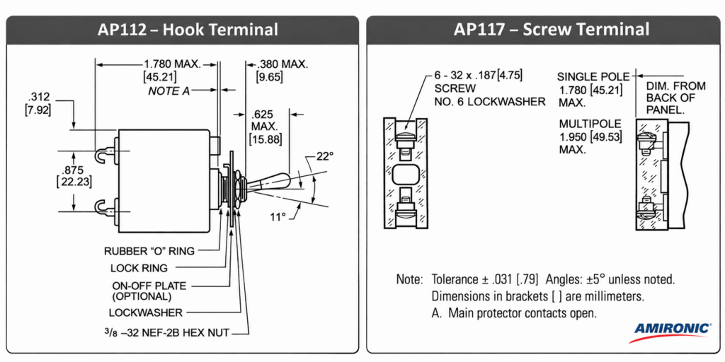
2. What Is a Hook Terminal? Construction, Connection Methods, and Applications

A Hook Terminal is an electrical terminal featuring a hook-shaped metal connection point, designed to accommodate wire termination through soldering or another suitable connection method, subject to the terminal design and manufacturer’s instructions.

Unlike a Screw Terminal, which uses a mechanical fastening mechanism to secure an electrical connection, a Hook Terminal does not incorporate an integrated screw-clamping mechanism.

In the AIRPAX AP series from Sensata Technologies, hook terminals are the standard connection configuration. The manufacturer describes these terminals as Heavy Copper Hooks, reflecting their physical construction.

2.1 Hook Terminal Construction

A Hook Terminal consists of a rigid metal conductor extending from the circuit breaker housing and terminating in a hook-shaped section.

This design provides a connection point where the electrical wire can be positioned and secured using an appropriate termination method.

Several engineering considerations should be addressed when designing a Hook Terminal connection:

  • Wire Compatibility: Wire gauge, conductor construction, and cross-sectional area must be suitable for the selected termination method.
  • Electrical Connection Quality: The connection must provide adequate electrical continuity and sufficiently low contact resistance for the intended application.
  • Mechanical Wire Support: The wiring arrangement should prevent excessive tensile loads, repeated bending, or mechanical stress from being transferred to the terminal connection.
  • Electrical Insulation and Clearance: Appropriate insulation and electrical clearances must be maintained between conductors, terminals, and adjacent conductive components.
  • Assembly and Inspection Accessibility: The circuit breaker location should allow proper wire termination, inspection, and quality verification during assembly.

In applications exposed to mechanical shock or vibration, particular attention should be given to wire harness support, strain relief, and prevention of repeated mechanical stress at the termination point.

Importantly, the hook-shaped terminal design alone does not guarantee vibration resistance.

The reliability of the completed electrical connection depends on the termination method, workmanship, conductor characteristics, and mechanical support of the wiring.

2.2 Hook Terminals in AIRPAX Hydraulic Magnetic Circuit Breakers

The AIRPAX AP series includes several circuit breaker configurations featuring Hook Terminals:

AIRPAX Model Number of Poles Terminal Type
AIRPAX AP1 1 Pole Hook Terminal
AIRPAX AP12 2 Poles Hook Terminal
AIRPAX AP112 3 Poles Hook Terminal

In multi-pole configurations, the circuit breaker incorporates a mechanically linked operating arrangement that allows multiple poles to be operated together.

For example, in a three-pole AIRPAX AP112 configured for common tripping, a trip initiated by one protected pole causes the associated poles to open through the common operating mechanism.

The exact tripping behavior depends on the selected internal configuration.

The AIRPAX AP series supports several internal circuit arrangements, including:

  • Series Trip: The current-sensing coil and the main circuit breaker contacts are connected in series with the protected load.
  • Shunt Trip: A configuration in which a separately energized trip circuit or coil can initiate circuit breaker operation, depending on the specific design.
  • Relay Trip: A configuration in which the trip-coil circuit is electrically isolated from the main contact circuit.
  • Auxiliary Switch: Additional contacts used for status indication, monitoring, or control functions, depending on the selected configuration.

The availability of different internal circuit arrangements is an important consideration when selecting an AIRPAX AP circuit breaker.

However, not every combination of poles, trip configurations, current ratings, and auxiliary contacts is necessarily available as a standard part number.

For special configurations or combinations of poles with different electrical characteristics, availability and compatibility should be verified with Sensata Technologies.

2.3 Advantages and Engineering Considerations of Hook Terminals

Hook Terminals may be particularly suitable for equipment in which wiring connections are predefined as part of a controlled manufacturing and assembly process.

Potential advantages:

  • Simple terminal construction without an integrated fastening screw.
  • Suitable for designing permanent wire connections as part of an electrical wiring harness.
  • Compatibility with controlled assembly processes using an appropriate wire termination method.
  • Availability of multiple internal trip configurations within the AIRPAX AP product family.

Engineering considerations and limitations:

  • Soldered connections, when used, require a controlled soldering process and appropriate workmanship standards.
  • Removing or replacing a permanently terminated conductor may require additional work compared with a screw-fastened connection.
  • Adequate mechanical support and strain relief must be provided for the wiring.
  • The selected termination method must meet the manufacturing, maintenance, inspection, and qualification requirements of the application.

The absence of a fastening screw should not be interpreted as an inherent reliability advantage.

Similarly, the use of a soldered connection does not automatically guarantee superior performance under shock or vibration.

The complete connection assembly must be evaluated against the operating conditions and applicable engineering requirements.

2.4 When Should You Consider a Hook Terminal?

Hook Terminals may be an appropriate choice when the application requires:

  • Permanent wiring connections integrated into a predefined wire harness.
  • Controlled manufacturing and assembly procedures.
  • A terminal configuration without an integrated screw-fastening mechanism.
  • Internal trip arrangements that are not available in the corresponding Screw Terminal versions.

In military and aerospace applications, terminal selection should not be based solely on physical terminal geometry.

Engineers should evaluate the circuit breaker as a complete component, including its electrical protection characteristics, mechanical installation, environmental performance, wiring method, and applicable qualification requirements.

The AIRPAX AP series includes sealed hydraulic magnetic circuit breakers, as well as military AP-MIL configurations manufactured and qualified in accordance with applicable requirements of MIL-PRF-39019.

However, not every AIRPAX circuit breaker equipped with Hook Terminals is a military-qualified component.

When a project specifies an M39019 part number, the exact military specification sheet, approved configuration, and applicable qualification status must be verified. A commercially available AP circuit breaker should not be considered an automatically interchangeable replacement simply because it uses the same terminal style.

Key Takeaway: Hook Terminal connections are not inherently superior or inferior to Screw Terminal connections. They represent a different electrical termination approach that should be selected according to the system architecture, manufacturing process, maintenance requirements, and environmental conditions.

For military applications, the final selection must also satisfy the applicable MIL-PRF-39019 requirements and the exact M39019 part number specification, where required.

3. What Is a Screw Terminal? Construction, Connection Methods, and Engineering Considerations

A Screw Terminal is an electrical connection terminal that uses a screw-fastening mechanism to secure an electrical connection. Unlike soldered connections, screw terminals rely on controlled mechanical fastening to establish and maintain electrical contact.

In the AIRPAX AP series from Sensata Technologies, Screw Terminal configurations incorporate a dedicated terminal block equipped with fastening screws.

Unlike Hook Terminals, which use heavy copper hook-shaped connection points, Screw Terminals provide a connection method based on mechanical fastening.

The choice between these terminal types can affect assembly procedures, wiring accessibility, maintenance requirements, and the space needed to integrate the circuit breaker into an electrical system.

3.1 Screw Terminal Construction

According to the AIRPAX AP/UP manufacturer catalog, the Screw Terminal configuration incorporates a terminal block with screws and lockwashers.

The manufacturer specifies 6-32 × 0.187-inch screws (approximately 4.75 mm in length) for this connection arrangement.

The terminal assembly includes several components:

  • Terminal Block: The structural assembly that supports the electrical terminals and fastening hardware.
  • Screw: The fastening component used to secure the electrical connection.
  • Lockwasher: A locking washer incorporated into the fastening assembly according to the manufacturer’s design.
  • Electrical Terminal: The conductive connection point through which the circuit breaker is connected to the external electrical circuit.

One practical advantage of screw-fastened connections is that wiring can be installed, disconnected, or replaced using appropriate tools without requiring a soldering process.

However, the conductor termination method, connection hardware, and fastening procedure must be compatible with the terminal design and manufacturer’s instructions.

Not every wire type, ring terminal, or cable lug is necessarily suitable for every screw terminal block. Compatibility should be verified before installation.

3.2 Tightening Torque – Why Does It Matter?

One of the most important installation parameters for Screw Terminals is tightening torque.

Tightening torque determines the rotational force applied to the fastening screw and influences the clamping force developed at the electrical connection.

Insufficient tightening may result in an inadequate mechanical or electrical connection, potentially increasing contact resistance or compromising connection integrity.

Excessive tightening may damage the screw, terminal, or associated connection hardware.

For AIRPAX AP/UP Screw Terminal configurations, the manufacturer specifies the following recommended tightening torque:

Parameter Manufacturer Specification
Terminal Type Screw Terminal
Screw Size 6-32
Recommended Tightening Torque 6–8 in-lbs
Metric Equivalent Approximately 0.68–0.90 N·m

The metric values are conversions of the manufacturer’s imperial torque specification.

During assembly, a suitable torque-controlled screwdriver or fastening tool should be used in accordance with the system’s manufacturing procedures.

In military, aerospace, and industrial applications, where equipment may be exposed to vibration or mechanical shock, additional attention should be given to:

  • Proper wire harness routing and mechanical support.
  • Prevention of excessive tensile or bending loads on the terminals.
  • Compatibility of wire termination hardware.
  • Controlled fastening procedures.
  • Inspection and quality assurance requirements defined for the project.

It is important to emphasize that correct tightening torque alone does not guarantee vibration resistance.

The reliability of the completed electrical connection depends on conductor characteristics, termination hardware, fastening procedures, mechanical support, and overall assembly quality.

3.3 Screw Terminals in AIRPAX Hydraulic Magnetic Circuit Breakers

The AIRPAX AP series includes three principal configurations featuring Screw Terminals:

AIRPAX Model Number of Poles Terminal Type
AIRPAX AP7 1 Pole Screw Terminal
AIRPAX AP17 2 Poles Screw Terminal
AIRPAX AP117 3 Poles Screw Terminal

These configurations correspond to Hook Terminal models with the same number of poles:

  • AP1 vs. AP7: Single-pole circuit breakers.
  • AP12 vs. AP17: Two-pole circuit breakers.
  • AP112 vs. AP117: Three-pole circuit breakers.

However, the corresponding models should not be considered directly interchangeable without engineering verification.

Beyond the terminal connection type, engineers must evaluate the internal circuit configuration, mounting dimensions, electrical ratings, tripping characteristics, and complete manufacturer part number.

This is particularly important when replacing a circuit breaker in an existing system, where even relatively small differences in terminal geometry or wiring access may affect installation.

3.4 Important Limitation: Screw Terminals Are Available with Series Trip Construction Only

According to the AIRPAX manufacturer catalog, Screw Terminal configurations are available with Series Trip construction only.

In a Series Trip circuit breaker, the current-sensing coil and the main switching contacts are connected in series with the protected load.

When the current reaches the applicable tripping conditions, as defined by the circuit breaker’s time-current characteristics, the protection mechanism operates to open the contacts.

Series Trip construction combines two functions within the same device:

  1. Overcurrent Protection: Automatic interruption of the protected circuit when the specified tripping conditions are reached.
  2. Manual Switching: The ability to open and close the circuit using the operating handle.

By comparison, Hook Terminal configurations within the AIRPAX AP series may also support additional internal arrangements, including Shunt Trip and Relay Trip, depending on the selected part number and design limitations.

This means that selecting between Hook Terminal and Screw Terminal is not necessarily a mechanical decision alone.

The terminal configuration may also determine which internal protection and control functions are available.

When an application requires a specialized tripping arrangement, engineers should first verify whether that configuration is supported with the requested terminal type.

3.5 Advantages and Engineering Considerations of Screw Terminals

Screw Terminals may be particularly suitable for applications where wiring accessibility, serviceability, or the ability to disconnect and reconnect conductors is an important design requirement.

Potential advantages:

  • Mechanical screw-fastened electrical connections without soldering.
  • Wiring can be disconnected and reconnected using suitable tools.
  • Manufacturer-defined tightening torque for controlled assembly.
  • Compatibility with manufacturing processes based on screw-fastened electrical connections.
  • Availability in single-pole, two-pole, and three-pole configurations within the AIRPAX AP series.

Engineering considerations and limitations:

  • The specified tightening torque must be applied during assembly.
  • Conductors, termination hardware, and terminal geometry must be compatible.
  • Sufficient installation space must be provided for the terminal block and fastening tools.
  • Inspection and maintenance procedures should follow the system’s engineering requirements.
  • Within the AIRPAX AP series, Screw Terminal configurations are limited to Series Trip construction.

Although screw-fastened connections can simplify certain maintenance operations, they should not automatically be considered more reliable than soldered Hook Terminal connections.

The suitability of either connection method depends on the complete electrical and mechanical design.

3.6 When Should You Consider a Screw Terminal?

Screw Terminals may be appropriate when the application requires:

  • Screw-fastened electrical connections.
  • Access to terminal connections during installation or maintenance.
  • The ability to disconnect and reconnect wiring without soldering.
  • Controlled fastening using a specified tightening torque.
  • A Series Trip circuit breaker configuration.

For example, when designing an electrical distribution panel or control system where technicians may need access to circuit breaker terminals, a Screw Terminal version may offer practical installation and maintenance advantages.

However, the selected model must still satisfy the electrical, mechanical, and environmental requirements of the application.

In systems featuring permanent wiring harnesses and controlled assembly processes, Hook Terminal configurations may be equally suitable.

For military and aerospace applications, additional verification may be necessary when the circuit breaker is specified under MIL-PRF-39019 or identified by an M39019 military part number.

A commercial AIRPAX AP7, AP17, or AP117 configuration should not be assumed to meet a particular military qualification requirement solely because its electrical ratings or terminal arrangement appear compatible.

The exact part number, applicable specification sheet, qualification status, and procurement requirements must be verified.

Key Takeaway: Screw Terminals provide a mechanically fastened electrical connection with a manufacturer-specified tightening torque, making them a practical option for applications requiring accessible or serviceable wiring.

However, terminal selection must consider the complete system requirements rather than installation convenience alone.

In the AIRPAX AP series, the restriction to Series Trip construction is a particularly important factor when comparing Screw Terminal models with their Hook Terminal counterparts.

4. Hook Terminal vs. Screw Terminal – An Engineering Comparison

Selecting the appropriate terminal type for a hydraulic magnetic circuit breaker affects wire termination, assembly procedures, maintenance accessibility, and, in some cases, the available internal circuit configurations.

Both Hook Terminal and Screw Terminal designs provide electrical connections between the circuit breaker and the protected circuit. However, they differ in mechanical construction, installation requirements, and practical integration considerations.

In the AIRPAX AP series from Sensata Technologies, terminal selection is reflected in the product family designation:

  • AP1, AP12, and AP112: Hook Terminal configurations.
  • AP7, AP17, and AP117: Screw Terminal configurations incorporating a terminal block.

Understanding these differences is particularly important when selecting circuit protection components for military, aerospace, and industrial equipment.

4.1 Comparison Table – Hook Terminal vs. Screw Terminal

Feature Hook Terminal Screw Terminal
Terminal Construction Heavy copper hook Screw connection with terminal block
Connection Method Suitable wire termination, such as soldering, subject to manufacturer instructions Mechanically fastened connection
Integrated Fastening Screw No Yes
Terminal Tightening Torque Not applicable to the hook terminal itself 6–8 in-lbs for AIRPAX AP Screw Terminals
Wire Removal and Reconnection Depends on termination method; soldered connections require additional work Possible by loosening and retightening the screw
Permanent Wiring Applications Suitable Suitable
Maintenance Considerations Depend on the wire termination method Require access to fastening screws and compliance with tightening instructions
Installation Space Depends on circuit breaker geometry and wire routing Must also accommodate the terminal block and tool access
Vibration Resistance Depends on the complete connection and installation Depends on the complete connection and installation
Available Internal Configurations in AIRPAX AP Series Trip, Shunt Trip, Relay Trip, and other options, subject to configuration Series Trip only
Three-Pole Model AIRPAX AP112 AIRPAX AP117

This comparison highlights structural and engineering differences. It does not establish that either terminal type provides inherently superior reliability, electrical performance, or environmental resistance.

The suitability of each connection method must be evaluated in the context of the complete electrical and mechanical assembly.

4.2 Is a Hook Terminal More Reliable Than a Screw Terminal?

A common engineering question, particularly in military and industrial applications, is whether a soldered Hook Terminal connection is more reliable than a screw-fastened connection.

The answer depends on the termination method, installation quality, and operating environment.

For a soldered Hook Terminal connection, important factors include:

  • Solder joint quality and workmanship.
  • Compatibility between the conductor and terminal.
  • Appropriate strain relief.
  • Prevention of repeated bending or mechanical stress near the solder joint.
  • Compliance with applicable manufacturing and inspection requirements.

For a Screw Terminal connection, important factors include:

  • Compatibility of the conductor and termination hardware.
  • Correct tightening torque.
  • Proper mechanical support of the wiring.
  • Maintaining electrical contact integrity throughout the service life.
  • Compliance with applicable assembly and maintenance procedures.

In both cases, proper wire harness design and mechanical support can be just as important as the terminal type itself.

The AIRPAX AP/UP manufacturer catalog does not provide comparative test data demonstrating that Hook Terminals are inherently more reliable than Screw Terminals, or vice versa.

Therefore, neither connection method should be considered universally superior without application-specific engineering evidence.

4.3 The Effects of Shock and Vibration on Terminal Selection

In military vehicles, aerospace equipment, industrial machinery, and mobile electronic systems, circuit breakers and their connected wiring may be exposed to mechanical shock and vibration.

These conditions require engineers to distinguish between two separate aspects of system reliability.

Circuit Breaker Environmental Performance

This refers to the ability of the circuit breaker mechanism to operate according to its specifications under defined environmental test conditions.

Electrical Connection Integrity

This refers to the ability of the connection between the external conductor and the circuit breaker terminal to maintain mechanical and electrical integrity during operation.

According to the AIRPAX AP manufacturer catalog, the series includes mechanical shock testing at 100G for 6 milliseconds, along with vibration testing under specified conditions referencing MIL-STD-202.

These tests address circuit breaker performance under defined mechanical conditions, including requirements related to unintended tripping, as applicable to the test procedure and configuration.

However, these specifications should not be interpreted as proof that every external wiring connection will withstand identical environmental conditions.

The complete installation must also be evaluated, including:

  • Wire and cable construction.
  • Terminal connection hardware.
  • Wire harness routing and support.
  • Strain relief and mechanical fastening.
  • Assembly workmanship and inspection procedures.

A circuit breaker that meets a specified shock or vibration requirement does not automatically guarantee that the entire wiring assembly meets the same requirement.

This distinction is especially important in military and aerospace applications, where electrical continuity and mechanical integrity may be critical to system operation.

4.4 How Terminal Type Affects System Design

Terminal selection should be considered during the early stages of electrical and mechanical system design, rather than treated as a minor assembly detail.

For example, replacing a Hook Terminal circuit breaker with a Screw Terminal version may require modifications to:

  • Wire termination methods.
  • Cable routing and harness geometry.
  • Available installation space.
  • Terminal accessibility.
  • Assembly and inspection procedures.

Even when two circuit breakers have the same number of poles, they should not automatically be considered mechanically or electrically interchangeable.

Within the AIRPAX AP series, there is an additional limitation:

Screw Terminal configurations are available with Series Trip construction only.

Therefore, when an application requires a Shunt Trip, Relay Trip, or another specialized internal arrangement, engineers may need to select a compatible Hook Terminal configuration or evaluate an alternative solution with the manufacturer.

For systems specified under MIL-PRF-39019, additional restrictions may apply.

A commercial AIRPAX AP model with similar electrical characteristics should not automatically be treated as an approved substitute for an M39019 military part number.

The applicable military specification sheet, qualification status, and exact component configuration must be verified before any substitution.

4.5 Practical Guidelines for Selecting the Right Terminal Type

When choosing between Hook Terminal and Screw Terminal configurations, engineers can use the following selection guidelines:

  1. Evaluate the Wiring Method: Determine whether the application requires permanent wire termination as part of a controlled harness assembly or a screw-fastened connection using compatible termination hardware.
  2. Define Maintenance Requirements: Consider whether conductors are likely to require disconnection, replacement, or reconnection during the equipment’s service life.
  3. Verify Installation Space: Confirm that the circuit breaker housing, terminals, wiring, and required tool access are compatible with the available mounting space.
  4. Consider Environmental Conditions: Mechanical shock, vibration, and temperature variations require evaluation of the complete connection assembly, not just the circuit breaker housing.
  5. Check the Internal Circuit Configuration: Within the AIRPAX AP series, Screw Terminal models are limited to Series Trip construction. Applications requiring other tripping arrangements must be evaluated accordingly.
  6. Verify the Complete Part Number: Replacing an AP112 with an AP117, or vice versa, requires verification of rated current, operating voltage, time-delay characteristics, internal configuration, mounting dimensions, and terminal arrangement.

For military applications, engineers should also verify whether the design specifies an M39019 part number, an approved manufacturer, or particular documentation and qualification requirements.

4.6 Which Is Better – Hook Terminal or Screw Terminal?

There is no single answer that applies to every electrical system.

Hook Terminal configurations may be appropriate for systems using permanent wire connections or requiring internal circuit arrangements that are unavailable with Screw Terminals.

Screw Terminal configurations may be preferable when the design requires mechanically fastened electrical connections, convenient access for wiring changes, or controlled assembly using a specified tightening torque.

Neither terminal type should be selected solely on the assumption that it provides better reliability under demanding environmental conditions.

The correct choice depends on the combined requirements of:

  • Electrical protection and circuit configuration.
  • Mechanical installation and available space.
  • Wire termination and assembly procedures.
  • Maintenance and serviceability.
  • Shock, vibration, and environmental conditions.
  • Applicable military or industrial qualification requirements.

For sealed AIRPAX AP hydraulic magnetic circuit breakers, terminal type is an integral part of the product configuration and should be evaluated during component selection, not only during wiring installation.

Key Takeaway: The choice between Hook Terminal and Screw Terminal is an engineering decision involving more than connection convenience. Proper selection requires consideration of electrical functionality, mechanical integration, installation procedures, and environmental requirements.

When working with MIL-PRF-39019-qualified circuit breakers or M39019 military part numbers, terminal compatibility must also be evaluated against the exact approved configuration and applicable procurement requirements.

5. Case Study: AIRPAX AP112 vs. AP117 – Comparing Three-Pole Hydraulic Magnetic Circuit Breakers

To illustrate the practical differences between Hook Terminal and Screw Terminal connections, let’s compare two three-pole hydraulic magnetic circuit protectors from the AIRPAX AP series manufactured by Sensata Technologies.

Both the AIRPAX AP112 and AP117 are designed to provide electrical circuit protection using a hydraulic magnetic operating mechanism. However, they differ in terminal construction and the range of available internal circuit configurations.

This comparison is particularly relevant to engineers designing military electronics, power distribution systems, communication equipment, and industrial control systems, where circuit breaker selection must account for electrical requirements, mechanical integration, and wiring methods.

5.1 AIRPAX AP112 – Three-Pole Circuit Breaker with Hook Terminals

The AIRPAX AP112 is a three-pole hydraulic magnetic circuit breaker featuring heavy copper Hook Terminals.

The design incorporates three poles within a common assembly, operated through a single handle mechanism.

Depending on the selected configuration, the assembly may incorporate poles with different protection characteristics, including different rated currents and time-delay curves.

One of the important advantages of the AP112 family is its flexibility in available internal circuit configurations.

The manufacturer describes several possible arrangements within the AP series, including:

  • Series Trip: Overcurrent protection using a current-sensing coil connected in series with the protected load.
  • Shunt Trip: An electrically initiated tripping arrangement using a separate trip circuit, subject to the selected configuration.
  • Relay Trip: A configuration in which the trip-coil circuit is electrically isolated from the main contact circuit.
  • Auxiliary Switch Options: Additional contacts for circuit breaker status indication and control applications.

For example, in a three-pole Series Trip configuration with common tripping, an overcurrent condition in one protected pole can activate the common trip mechanism, causing all three poles to open.

However, when a special configuration or a combination of poles with different electrical characteristics is required, the exact part number and configuration must be verified with Sensata Technologies.

5.2 AIRPAX AP117 – Three-Pole Circuit Breaker with Screw Terminals

The AIRPAX AP117 is the three-pole Screw Terminal version within the AIRPAX AP family.

Instead of heavy copper Hook Terminals, the AP117 uses screw-fastened electrical connections incorporated into a dedicated terminal block.

According to the manufacturer’s catalog, Screw Terminal configurations are available with Series Trip construction only.

Therefore, the AP117 is suitable for applications requiring Series Trip overcurrent protection together with a screw-fastened wiring arrangement.

The manufacturer specifies a recommended tightening torque of 6–8 in-lbs (approximately 0.68–0.90 N·m) for the 6-32 terminal screws.

When designing the installation, engineers should also consider the additional space required for the terminal block, wire routing, and access to the fastening screws during assembly and maintenance.

5.3 Comparison Table – AIRPAX AP112 vs. AP117

Feature AIRPAX AP112 AIRPAX AP117
Number of Poles 3 3
Terminal Type Hook Terminal Screw Terminal
Terminal Construction Heavy Copper Hooks Screw-Fastened Terminal Block
Operating Mechanism Hydraulic Magnetic Hydraulic Magnetic
Common Mechanical Operation Yes Yes
Series Trip Available Available
Shunt Trip / Relay Trip Available in applicable configurations Not available with the standard Screw Terminal arrangement
Auxiliary Switch Available depending on part number R-type terminals, subject to configuration availability
Terminal Tightening Torque Not applicable to the hook terminal itself 6–8 in-lbs
Military Applications Subject to exact version and qualification requirements Subject to exact version and qualification requirements

Important: AP112 and AP117 are product family designations rather than complete ordering part numbers.

A complete circuit breaker specification must also define the internal circuit configuration, rated current, time-delay characteristics, operating voltage requirements, and any additional options.

The exact combination of features must be verified against the manufacturer’s ordering information.

5.4 Auxiliary Switch Options – Adding Circuit Breaker Status Indication

In addition to overcurrent protection, many electrical systems require an electrical signal indicating the status of a circuit breaker.

For this purpose, the AIRPAX AP series offers an optional Auxiliary Switch, providing a separate set of contacts electrically isolated from the main power circuit.

Depending on the application, an Auxiliary Switch can be used to:

  • Provide a status signal to a control system.
  • Operate a remote indicator lamp.
  • Supply a signal to a digital input.
  • Integrate circuit breaker status into monitoring or supervisory equipment.

According to the AIRPAX catalog, the Auxiliary Switch uses an SPDT (Single Pole Double Throw) contact arrangement with three electrical connections:

  • COM (Common): The common contact.
  • NO (Normally Open): The contact that is open in the defined reference state.
  • NC (Normally Closed): The contact that is closed in the defined reference state.

The actual contact state relative to the circuit breaker’s operating position must be confirmed using the wiring diagram for the selected part number.

An Auxiliary Switch should not automatically be assumed to provide a dedicated trip-alarm signal. Its indication function depends on the specific switch design and operating arrangement.

Auxiliary Switch Terminal Options

The AIRPAX AP series offers two terminal configurations for the Auxiliary Switch.

Option 1: Pierced Pin Terminals – R Configuration

The R configuration uses flattened and pierced solder terminals.

Each terminal incorporates an opening that allows a conductor to be positioned for an appropriate soldered connection.

This configuration is identified by the code R, as illustrated by the example designation AP1-1R.

Option 2: Cane Hook Terminals – RC Configuration

The RC configuration uses cane hook-shaped solder terminals.

These terminals provide a curved connection point suitable for a soldered wire termination using an appropriate assembly method.

This configuration is identified by the code RC, as illustrated by the example designation AP1-1RC.

It is important to distinguish between the main power terminals of the circuit breaker and the Auxiliary Switch terminals.

These are separate configuration characteristics and should be specified independently.

Can an Auxiliary Switch Be Ordered with Screw Terminals?

Yes, but an important limitation applies.

According to the AIRPAX catalog, Screw Terminal versions in the AP7, AP17, and AP117 families support the SPDT Auxiliary Switch with R-type Pierced Pin Terminals only.

By comparison, applicable Hook Terminal configurations may support either R or RC Auxiliary Switch terminals, depending on the specific part number and manufacturer-approved options.

Therefore, when specifying a three-pole circuit breaker with an Auxiliary Switch, engineers must define both the main terminal type and the Auxiliary Switch terminal arrangement.

5.5 How to Select the Right Auxiliary Switch Configuration

When choosing a hydraulic magnetic circuit breaker with an Auxiliary Switch, several factors should be evaluated:

  1. Indication Requirements: Determine whether the Auxiliary Switch will provide a signal to a control system, indicator lamp, alarm circuit, or remote monitoring system.
  2. Electrical Compatibility: Verify that the voltage and current requirements of the indication circuit are compatible with the Auxiliary Switch contact ratings.
  3. Terminal Connection Method: Confirm whether the assembly process is compatible with Pierced Pin or Cane Hook solder terminals.
  4. Main Terminal Configuration: Remember that selecting Screw Terminals limits the Auxiliary Switch terminal option to the R configuration.
  5. Complete Part Number: Verify that the required combination of pole count, internal circuit configuration, Auxiliary Switch, and protection characteristics is available and approved by the manufacturer.

Auxiliary Switch contacts are intended for appropriately rated indication and control circuits.

They must not be used as main power-switching contacts unless the application is explicitly compatible with their specified electrical ratings.

5.6 Practical Example – Selecting a Three-Pole Circuit Breaker with Remote Status Indication

Consider a military electronic system with three power circuits requiring a sealed hydraulic magnetic circuit breaker capable of common disconnection.

The system also requires an electrical status signal to be transmitted to a central control unit.

In this case, engineers may evaluate the AIRPAX AP112 or AP117, depending on the preferred wiring arrangement and required internal circuit configuration.

Option A: AIRPAX AP112 with Hook Terminals

If the system uses permanent wire connections, the AP112 may be considered.

Depending on the selected configuration, an Auxiliary Switch with R or RC terminals may be available.

Option B: AIRPAX AP117 with Screw Terminals

If the system requires screw-fastened wiring connections and Series Trip protection, the AP117 may be considered.

In this arrangement, the Auxiliary Switch terminal option is limited to R-type Pierced Pin Terminals.

In both cases, engineers must verify:

  • Rated current for each protected pole.
  • Operating voltage and applicable interrupting capacity.
  • Time-delay characteristics.
  • Internal circuit and common-trip configuration.
  • Auxiliary Switch contact ratings and operating behavior.
  • Mechanical dimensions and wiring accessibility.
  • Environmental and qualification requirements.

For military applications requiring MIL-PRF-39019 compliance, the selected commercial AP configuration must not be assumed to be equivalent to a qualified M39019 military part number.

The exact qualification status, approved configuration, and applicable specification sheet must be verified separately.

This example demonstrates how terminal selection can affect not only the main electrical connections but also the available wiring arrangements for monitoring and control circuits.

5.7 Case Study Summary

The comparison between the AIRPAX AP112 and AP117 demonstrates that terminal type is an integral part of circuit breaker selection.

Both models belong to the AIRPAX AP family of sealed hydraulic magnetic circuit protectors, but they differ in their connection methods and available configuration options.

AIRPAX AP112 provides Hook Terminal connections and greater flexibility in the available internal circuit arrangements.

AIRPAX AP117 provides Screw Terminal connections through a terminal block but is limited to Series Trip construction.

Both product families may support an optional Auxiliary Switch, subject to the relevant terminal restrictions and approved part number configurations.

For engineers selecting hydraulic magnetic circuit breakers for military, aerospace, or industrial applications, the specification should therefore address not only the protection characteristics but also the main terminal type, Auxiliary Switch requirements, and the connection method used by the control system.

Key Takeaway: AP112 and AP117 should not be treated as automatically interchangeable three-pole circuit breakers. Their terminal construction, internal circuit configuration options, and Auxiliary Switch connection limitations must be considered alongside the electrical ratings and environmental requirements of the application.

6. Selecting Rated Current, Time-Delay Characteristics, and Operating Frequency in AIRPAX AP/UP Circuit Breakers

After selecting the appropriate terminal configuration—Hook Terminal or Screw Terminal—the next step is to define the electrical protection characteristics of the circuit breaker.

For AIRPAX AP/UP hydraulic magnetic circuit breakers from Sensata Technologies, component selection involves more than choosing the number of poles and rated current. Engineers must also consider operating voltage, frequency, time-delay characteristics, inrush current, interrupting capacity, and internal circuit configuration.

In military and aerospace applications, where a specific military part number such as M39019/02-219S or M39019/04-230S may be required, accurate identification of these parameters is particularly important.

6.1 Rated Current – Selecting the Appropriate Current Rating

The rated current defines the nominal current rating of the circuit breaker and serves as a reference for its time-current tripping characteristics.

According to the AIRPAX AP product information, the series includes current ratings ranging from 0.05A to 20A, subject to the selected electrical and mechanical configuration.

Examples of available current ratings include:

0.5A, 1A, 2A, 3A, 5A, 7.5A, 10A, 15A, and 20A.

When selecting the rated current, engineers should evaluate:

  • Continuous Load Current: The expected current during normal operation.
  • Inrush Current: Temporary current peaks during equipment startup or energization.
  • Load Characteristics: Whether the protected circuit contains motors, power supplies, capacitive loads, or other components with transient current demands.
  • Operating Conditions: The electrical and environmental conditions under which the circuit breaker will operate.
  • Circuit Protection Requirements: Coordination with the wiring, connected equipment, and applicable protection criteria.

It is important to distinguish between the circuit breaker’s rated current and the actual current at which it will trip.

A circuit breaker rated at 10A does not necessarily trip immediately when the current exceeds 10A.

Its response depends on the time-current characteristic curve, the magnitude and duration of the overcurrent, and the applicable operating conditions.

For military part numbers in the M39019 family, the required current rating must be identified from the applicable military specification sheet and exact part number.

The numerical suffix of an M39019 part number should not be interpreted as a direct current rating without consulting the relevant specification.

6.2 Time-Delay Characteristics – Why the Trip Curve Matters

One of the important advantages of hydraulic magnetic circuit protection is the availability of different time-delay characteristics.

These characteristics allow engineers to coordinate circuit breaker operation with the electrical behavior of the protected load.

For example, power supplies, electric motors, and capacitive circuits may draw a temporary inrush current significantly higher than their normal operating current.

If a circuit breaker responds too quickly to this temporary current, it may cause nuisance tripping, interrupting equipment operation even though no sustained overload exists.

The AIRPAX AP series offers different time-delay options, including:

Time-Delay Characteristic General Description
Instantaneous Rapid tripping according to the specified trip characteristics
Short Time Delay Relatively short delay before tripping under defined overcurrent conditions
Long Time Delay Longer delay intended for applications requiring greater tolerance of temporary overcurrent
High Pulse Tolerance Configurations designed to provide increased tolerance of certain transient current pulses

The manufacturer identifies specific time-delay characteristics through numerical codes.

Examples from the AIRPAX AP time-delay selections include:

Time-Delay Code Application Characteristic
51 DC Short Time Delay
52 DC Long Time Delay
61 50/60 Hz AC Short Time Delay
62 50/60 Hz AC Long Time Delay
64 50/60 Hz AC Short Time Delay with enhanced pulse tolerance
65 50/60 Hz AC Long Time Delay with enhanced pulse tolerance

Additional time-delay codes may be available for other frequencies and application requirements.

A time-delay characteristic should never be selected based solely on labels such as Short or Long.

Engineers should review the manufacturer’s actual Time-Current Curves, including the relevant test conditions and tolerances.

This is especially important when the protected circuit contains sensitive electronic equipment or experiences high startup currents.

Time-Delay Selection in Military M39019 Circuit Breakers

When a system specifies a military circuit breaker such as M39019/02-255S, the required time-delay characteristics form part of the exact military-defined configuration.

A commercial AIRPAX circuit breaker with a similar rated current and nominal delay characteristic is not automatically an approved replacement.

For military procurement, engineers should verify the specified electrical characteristics against the applicable MIL-PRF-39019 specification sheet, manufacturer documentation, and approved configuration.

6.3 Operating Voltage and Frequency

AIRPAX AP hydraulic magnetic circuit breakers are available in configurations intended for different electrical systems, including:

  • DC Circuits: Direct-current power distribution and equipment protection.
  • 50/60 Hz AC Circuits: Conventional alternating-current power systems.
  • 400 Hz AC Circuits: Electrical systems operating at higher AC frequencies, including certain aerospace applications.

The operating frequency is particularly important because the current-sensing and time-delay characteristics of a hydraulic magnetic circuit breaker are configuration-dependent.

A circuit breaker designed for DC operation should not automatically be assumed suitable for AC operation at the same nominal voltage.

Likewise, a circuit breaker intended for 50/60 Hz operation should not be assumed suitable for 400 Hz without verifying the manufacturer’s specifications.

Engineers must confirm the combination of:

  • Rated operating voltage.
  • Rated current.
  • AC frequency or DC operation.
  • Time-delay characteristic.
  • Interrupting capacity.
  • Complete circuit breaker part number.

For aerospace and military systems, these requirements may be defined directly by the equipment specification or by a designated M39019 military part number.

6.4 Interrupting Capacity – A Critical Protection Parameter

Interrupting Capacity is the maximum prospective fault current that a circuit breaker is rated to interrupt safely under specified electrical and test conditions.

It is fundamentally different from the rated current.

For example, a circuit breaker may have a rated current of 5A or 10A while being required to interrupt a much higher current during a short-circuit fault.

The AIRPAX technical information identifies the following interrupting-capacity values in the context of specified MIL-PRF-39019 ratings:

Operating Voltage Specified Interrupting Capacity
50 VDC 500A
120 VAC 500A
240 VAC 300A

These values apply to the relevant configurations and specified test conditions. They must not be generalized to every AIRPAX AP/UP model or every operating environment.

In military and industrial power distribution systems, the selected circuit breaker’s interrupting capacity must be suitable for the prospective short-circuit current at the installation point.

A circuit breaker with an appropriate rated current but insufficient interrupting capacity may not provide the required fault protection.

For an M39019 circuit breaker, the applicable interrupting-capacity requirements must be verified against the exact military specification and qualified configuration.

6.5 Why the Complete Part Number Matters

Selecting a hydraulic magnetic circuit breaker requires several electrical and mechanical parameters to be considered together.

For commercial AIRPAX AP configurations, these may include the terminal type, number of poles, internal trip arrangement, rated current, time-delay code, and optional Auxiliary Switch.

Military circuit breakers introduce another level of identification.

Consider the following example part numbers:

Example Military Part Number Identification
M39019/02-219S Configuration identified under specification sheet /02
M39019/02-255S Another configuration identified under specification sheet /02
M39019/04-230S Configuration identified under specification sheet /04

These examples illustrate how the military part-numbering system distinguishes between different specification sheets and configurations.

However, the suffixes 219S, 255S, and 230S should not be decoded using assumptions based on commercial AIRPAX ordering codes.

The actual current rating, number of poles, terminal arrangement, time-delay characteristics, and other requirements must be established from the relevant military specification sheet.

Key Takeaway: Selecting the correct AIRPAX hydraulic magnetic circuit breaker requires coordination between rated current, time-delay characteristics, operating voltage, frequency, and interrupting capacity.

For military applications, the complete M39019 part number is a critical technical identifier. Similar commercial specifications do not automatically establish interchangeability or military qualification.

7. AIRPAX AP-MIL Military Circuit Breakers and MIL-PRF-39019 – Understanding Military Part Numbers

When selecting a hydraulic magnetic circuit breaker for military or aerospace equipment, engineers must distinguish between a commercial component designed for demanding environments and a component qualified to a specific military specification.

The AIRPAX AP-MIL series from Sensata Technologies includes sealed hydraulic magnetic circuit breakers designed to meet applicable requirements of MIL-PRF-39019.

These circuit breakers are used in applications where electrical protection, mechanical performance, environmental resistance, and procurement traceability must satisfy defined requirements.

For military procurement, identifying the correct component involves more than matching its current rating or physical dimensions. The exact M39019 military part number, applicable specification sheet, and qualified manufacturer must also be considered.

7.1 What Is MIL-PRF-39019?

MIL-PRF-39019 is a United States military performance specification covering low-power, sealed, trip-free magnetic circuit breakers.

The specification establishes requirements and test procedures for circuit breakers intended for defined electrical and environmental conditions.

Its scope includes:

  • Single-pole and multi-pole circuit breakers.
  • Rated currents from 0.05A to 20A.
  • AC applications up to 240V at specified frequencies.
  • DC applications up to 50V.
  • Trip-free operating mechanisms.
  • Sealed construction.
  • Optional auxiliary contacts and monitoring terminals.

The specification is used together with individual Specification Sheets, commonly called Slash Sheets, which define the requirements for particular circuit breaker configurations.

The objective is to provide a standardized technical basis for component qualification, identification, testing, and procurement.

7.2 Understanding the MIL-PRF-39019 Specification Sheets

One of the most useful aspects of the M39019 numbering system is that the specification sheet identifies the basic circuit breaker configuration.

The MIL-PRF-39019 specification family includes six principal sheets:

Specification Sheet Circuit Breaker Configuration
MIL-PRF-39019/1 One-Pole Circuit Breaker
MIL-PRF-39019/2 One-Pole Circuit Breaker with Auxiliary Contacts
MIL-PRF-39019/3 Two-Pole Circuit Breaker
MIL-PRF-39019/4 Two-Pole Circuit Breaker with Auxiliary Contacts
MIL-PRF-39019/5 Three-Pole Circuit Breaker
MIL-PRF-39019/6 Three-Pole Circuit Breaker with Auxiliary Contacts

This distinction is particularly valuable when reviewing military drawings, bills of materials, or requests for quotation.

For example:

  • M39019/02 identifies the one-pole family with auxiliary contacts.
  • M39019/04 identifies the two-pole family with auxiliary contacts.
  • M39019/06 identifies the three-pole family with auxiliary contacts.

However, the specification sheet alone does not identify the complete electrical and mechanical configuration.

The full dash number must also be considered.

7.3 How to Read an M39019 Military Circuit Breaker Part Number

A typical military circuit breaker part number follows this general structure:

M39019/02-219S

The designation can be divided into three principal elements.

Part Number Element Meaning
M39019 Military part-number family governed by MIL-PRF-39019
/02 Specification sheet identifying a one-pole circuit breaker with auxiliary contacts
-219S Specific configuration designation defined by the applicable specification sheet

Specific configuration designation, including any applicable suffix, as defined by the relevant military specification sheet.

Its meaning must be established from the applicable military specification sheet, including the relevant tables, drawings, and notes.

Example 1: M39019/02-219S

This designation belongs to the MIL-PRF-39019/2 family.

Therefore, its specification sheet identifies a one-pole sealed magnetic circuit breaker with auxiliary contacts.

The 219S suffix identifies a particular configuration within that sheet.

To determine its exact electrical and mechanical characteristics, engineers must consult the applicable specification tables.

Example 2: M39019/02-255S

This part number belongs to the same /02 specification-sheet family as the previous example.

Both are therefore associated with one-pole circuit breakers with auxiliary contacts.

However, the different dash numbers indicate different specified configurations.

The two part numbers should not be considered interchangeable simply because they share the same specification sheet.

Example 3: M39019/04-230S

This designation belongs to the MIL-PRF-39019/4 family.

Unlike the previous examples, the /04 specification sheet covers two-pole circuit breakers with auxiliary contacts.

This illustrates why the slash-sheet designation is important.

A procurement request for M39019/04-230S must not be treated as equivalent to a part number from the /02 family without a formal engineering assessment.

The exact characteristics associated with the -230S suffix must be verified against the applicable specification sheet.

7.4 AIRPAX Commercial Part Numbers vs. M39019 Military Part Numbers

AIRPAX commercial circuit breakers and military-qualified AP-MIL configurations may share certain design principles, mechanical features, and electrical characteristics.

However, their identification systems serve different purposes.

Commercial AIRPAX AP Part Numbers

Commercial part numbers identify configurations selected from the AIRPAX product catalog, including features such as:

  • Number of poles.
  • Main terminal configuration.
  • Internal trip arrangement.
  • Rated current.
  • Time-delay characteristic.
  • Auxiliary Switch options.

For example, the AP112 and AP117 families distinguish between three-pole Hook Terminal and Screw Terminal constructions.

Military M39019 Part Numbers

Military part numbers identify configurations defined by the applicable military specification sheet.

The identification incorporates requirements that may extend beyond the electrical ratings of a commercial equivalent.

These may include qualification requirements, specified construction, inspection criteria, marking, and procurement documentation.

Consequently, a commercial AIRPAX part number and an M39019 military designation should not automatically be considered interchangeable.

Even when the electrical characteristics appear similar, qualification and configuration requirements must be verified separately.

7.5 What Is QPL Qualification?

QPL stands for Qualified Products List.

In the MIL-PRF-39019 context, qualification identifies products and manufacturers that have been evaluated against the applicable military specification requirements.

The traditional QPL-39019 listing has been transformed into an electronic Qualified Products Database (QPD).

The QPD provides a means of checking qualified product information associated with the governing specification.

For procurement purposes, engineers and purchasing departments should verify:

  1. The exact military part number.
  2. The applicable specification sheet.
  3. The qualified manufacturer and relevant manufacturing identification.
  4. The qualification status of the required configuration.
  5. Any project-specific documentation, traceability, or inspection requirements.

A manufacturer’s general statement that a product is suitable for military applications does not automatically establish that the exact part number is qualified.

Similarly, the existence of a military part number does not eliminate the need to verify the approved source and applicable procurement requirements.

7.6 Environmental Performance of AIRPAX AP-MIL Circuit Breakers

The AIRPAX AP family incorporates features intended for applications requiring reliable circuit protection under demanding operating conditions.

The manufacturer’s technical information identifies characteristics such as:

Characteristic AIRPAX AP Technical Information
Operating Temperature −40°C to +100°C under specified conditions
Mechanical Shock 100G for 6 ms under specified test conditions
Vibration Testing covering frequencies up to 2,000 Hz under specified conditions
Construction Fully Sealed
Operating Mechanism Trip-Free
Panel Sealing O-ring and appropriate mounting arrangement

These characteristics are relevant when evaluating circuit breakers for military electronics, aerospace systems, communication equipment, and industrial applications.

However, the environmental performance of the circuit breaker itself must be distinguished from that of the complete installation.

For example, successful circuit breaker shock testing does not automatically establish that the external wiring, solder joints, terminal hardware, and wire harness support will meet the same requirements.

The exact environmental requirements applicable to an M39019 component must be determined from the governing specification, relevant slash sheet, and qualified configuration.

7.7 Can an M39019 Circuit Breaker Be Replaced with a Commercial AIRPAX Model?

In some cases, a commercial AIRPAX AP circuit breaker may have electrical or mechanical characteristics similar to those of a military-qualified AP-MIL component.

However, similarity does not automatically establish equivalence.

Before considering a replacement, engineers should verify:

  1. Electrical Ratings: Rated current, operating voltage, frequency, and interrupting capacity.
  2. Protection Characteristics: Time-current curves, trip configuration, and required operating behavior.
  3. Mechanical Compatibility: Mounting dimensions, terminal positions, and installation requirements.
  4. Terminal Configuration: Hook Terminal, Screw Terminal, or another specified connection arrangement.
  5. Auxiliary Contacts: Contact configuration, electrical ratings, and terminal type.
  6. Military Qualification: Applicable MIL-PRF-39019 requirements and qualified product status.
  7. Documentation and Traceability: Certificate of Conformity (COC), manufacturer identification, and other required records.
  8. Engineering Approval: Authorization from the responsible design authority before changing a specified component.

For example, replacing M39019/02-219S with a commercial AIRPAX component requires more than finding a one-pole circuit breaker with similar current and voltage ratings.

The auxiliary contact arrangement, time-delay characteristics, physical construction, and military qualification requirements must also be evaluated.

Likewise, replacing M39019/04-230S requires consideration of its two-pole configuration and auxiliary contacts, in addition to the complete electrical and qualification requirements.

Electrical compatibility does not automatically mean military specification compliance.

7.8 Practical Guidelines for Ordering M39019 Circuit Breakers

When requesting a quotation or placing an order for an M39019 circuit breaker, providing complete technical information helps prevent configuration errors and unnecessary delays.

Recommended information includes:

  • Complete Military Part Number: For example, M39019/02-219S or M39019/04-230S.
  • Required Quantity: Including any planned production or future demand.
  • Applicable Drawing or Specification: Particularly when a specific revision or approved configuration is required.
  • Manufacturer Requirements: Including any approved-source restrictions.
  • Qualification Requirements: QPD status and other applicable project conditions.
  • Country of Origin Requirements: Where required by the customer or procurement contract.
  • Documentation Requirements: Such as a Certificate of Conformity, traceability records, or other specified documentation.
  • Required Delivery Date: Including any project schedule constraints.

When a requested part number is obsolete, unavailable, or subject to an extended lead time, possible alternatives should be evaluated with the manufacturer and the responsible engineering authority.

A proposed alternative must not be treated as approved until the relevant technical and procurement requirements have been satisfied.

7.9 Why Military Part-Number Identification Matters

Military circuit breaker procurement is not simply a matter of finding a component with the correct current rating.

The specification-sheet designation, dash number, qualification status, and approved configuration are all part of the component identification process.

For engineers, understanding the M39019 numbering system helps identify the required circuit breaker family and determine which technical documentation must be reviewed.

For procurement professionals, it helps reduce the risk of ordering an incorrect configuration or accepting an unapproved substitute.

For maintenance and replacement applications, it provides a structured approach to evaluating compatibility and traceability.

Key Takeaway: AIRPAX AP-MIL circuit breakers combine hydraulic magnetic protection technology with configurations defined under MIL-PRF-39019.

Part numbers such as M39019/02-219S, M39019/02-255S, and M39019/04-230S should be treated as precise technical identifiers, not generic descriptions of similar circuit breakers.

Correct selection requires verification of the applicable specification sheet, complete dash number, qualified manufacturer, and project-specific requirements.

8. How to Select a Sealed Hydraulic Magnetic Circuit Breaker for Military Applications

Selecting a hydraulic magnetic circuit breaker for military or aerospace applications requires a systematic evaluation of electrical, mechanical, environmental, and qualification requirements.

The correct circuit breaker cannot be selected based solely on its rated current or number of poles.

Engineers must consider the complete system architecture, including operating voltage, inrush current, time-delay characteristics, terminal configuration, environmental conditions, and applicable military specifications.

For applications requiring MIL-PRF-39019 compliance, the selection process must also address the exact military part number, applicable specification sheet, and qualified product requirements.

The following guidelines provide a practical approach to selecting an appropriate AIRPAX AP/UP or AP-MIL circuit breaker.

8.1 Define the Electrical Protection Requirements

The first step is to establish the electrical characteristics of the circuit being protected.

Important parameters include:

  • Operating Voltage: Determine whether the circuit operates on DC or AC power and identify the maximum applicable voltage.
  • Continuous Load Current: Establish the expected current during normal operation.
  • Inrush Current: Identify temporary current peaks during startup, switching, or equipment energization.
  • Operating Frequency: Confirm whether the application requires DC, 50/60 Hz AC, or 400 Hz AC operation.
  • Prospective Short-Circuit Current: Determine the maximum fault current that may occur at the circuit breaker’s installation point.
  • Required Time-Delay Characteristics: Select a protection curve compatible with the load and the required response to overcurrent conditions.

For example, an electronic power supply may draw a significant inrush current when its input capacitors are initially charged.

A circuit breaker with an excessively fast response may trip during normal startup, even when no sustained overload is present.

Conversely, an excessively long delay may fail to provide the required protection for sensitive equipment or wiring.

Therefore, the selected Time-Current Curve must be evaluated against the actual load characteristics and protection requirements.

For military applications, these electrical parameters may already be defined by an approved M39019 part number.

When a specific military part number is required, engineers should verify its characteristics rather than attempting to reconstruct the specification from a commercial circuit breaker designation.

8.2 Select the Number of Poles

The AIRPAX AP series includes single-pole, two-pole, and three-pole configurations.

The number of poles should be selected according to the electrical system architecture and the required switching and protection functions.

Number of Poles Typical Design Consideration
1 Pole Protection and switching of a single circuit conductor
2 Poles Applications requiring coordinated switching of two conductors
3 Poles Applications requiring coordinated switching of three conductors

For multi-pole circuit breakers, engineers must verify the operating arrangement and the tripping characteristics of each pole.

Where Common Trip functionality is required, the selected configuration must provide the intended simultaneous disconnection behavior.

The number of poles alone does not establish the complete internal circuit arrangement.

Number of Poles in M39019 Military Part Numbers

The applicable MIL-PRF-39019 specification sheet provides an important starting point for identifying the required configuration.

Examples include:

Military Part Number Family General Configuration
M39019/01 One-Pole Circuit Breaker
M39019/02 One-Pole Circuit Breaker with Auxiliary Contacts
M39019/03 Two-Pole Circuit Breaker
M39019/04 Two-Pole Circuit Breaker with Auxiliary Contacts
M39019/05 Three-Pole Circuit Breaker
M39019/06 Three-Pole Circuit Breaker with Auxiliary Contacts

For example, M39019/02-219S and M39019/04-230S belong to different specification-sheet families and should not be treated as equivalent configurations.

The complete dash number must still be checked to establish the exact electrical and mechanical requirements.

8.3 Choose Hook Terminal or Screw Terminal

Terminal selection is an important part of circuit breaker integration.

Within the AIRPAX AP series, engineers can evaluate the following product families:

Terminal Type Single-Pole Two-Pole Three-Pole
Hook Terminal AP1 AP12 AP112
Screw Terminal AP7 AP17 AP117

Hook Terminal configurations may be appropriate for systems using permanent wire connections, controlled harness assembly processes, or specialized internal circuit arrangements.

Screw Terminal configurations may be suitable where screw-fastened connections, accessible wiring, or the ability to disconnect and reconnect conductors is required.

However, a significant limitation applies:

AIRPAX AP Screw Terminal configurations are available with Series Trip construction only.

Therefore, applications requiring Shunt Trip, Relay Trip, or other specialized arrangements must be evaluated for compatibility with the selected terminal configuration.

Engineers should also verify:

  • Terminal geometry and installation dimensions.
  • Compatible conductor termination methods.
  • Wire harness routing and strain relief.
  • Assembly and inspection requirements.
  • Accessibility for installation and maintenance.

For military applications, terminal type must also match the exact approved configuration when specified by the applicable military part number or engineering drawing.

8.4 Determine Whether an Auxiliary Switch Is Required

Many military electronic systems require remote indication of circuit breaker status.

An optional Auxiliary Switch can provide an electrical signal to a control or monitoring system without using the main power contacts for the indication circuit.

Typical applications include:

  • Circuit breaker status monitoring.
  • Remote control-panel indication.
  • Digital inputs to monitoring equipment.
  • Maintenance and diagnostic interfaces.
  • Equipment status reporting.

The AIRPAX AP series offers an optional SPDT Auxiliary Switch, subject to the selected circuit breaker configuration.

Two auxiliary terminal arrangements are identified in the product information:

  • R – Pierced Pin Terminals: Flattened and pierced solder terminals.
  • RC – Cane Hook Terminals: Hook-shaped solder terminals.

For AIRPAX Screw Terminal configurations, the Auxiliary Switch option is limited to R-type terminals, subject to the applicable ordering configuration.

Before specifying an Auxiliary Switch, engineers should confirm its electrical ratings, contact arrangement, operating behavior, and compatibility with the monitoring circuit.

An Auxiliary Switch should not automatically be interpreted as a dedicated fault or trip indication contact. Its actual function depends on the specific configuration.

For military part numbers such as M39019/02-255S or M39019/04-230S, the applicable specification sheet identifies a circuit breaker family with auxiliary contacts.

The exact contact arrangement and other technical characteristics must be verified using the full military part number.

8.5 Verify Military Specification and Qualification Requirements

When a project specifies MIL-PRF-39019 or an M39019 military part number, component selection must include verification of the applicable military requirements.

A circuit breaker described as Military Grade or suitable for defense applications is not necessarily qualified to the required military specification.

The verification process should include:

  1. Military Specification: Confirm that MIL-PRF-39019 is the applicable governing specification.
  2. Specification Sheet: Identify the required slash sheet, such as /02 or /04.
  3. Complete Part Number: Verify the exact dash number and suffix.
  4. Qualified Manufacturer: Confirm the approved manufacturer and applicable qualification status.
  5. Technical Configuration: Verify electrical ratings, mechanical construction, terminals, and auxiliary contacts.
  6. Procurement Documentation: Confirm the required certificates, traceability information, and inspection records.

Where applicable, qualification information should be checked against the relevant Qualified Products Database (QPD).

The presence of a military-style part number in a supplier catalog does not, by itself, establish that the offered component satisfies every procurement requirement.

Example: Evaluating an M39019 Replacement

Suppose a military equipment manufacturer specifies M39019/04-230S in an approved bill of materials.

A proposed replacement should not be evaluated solely by comparing its rated current and voltage.

The evaluation must also address the two-pole configuration with auxiliary contacts, the specific electrical characteristics, terminal arrangement, mechanical compatibility, qualification status, and any project-specific requirements.

If a commercial AIRPAX component is proposed as an alternative, the responsible engineering authority must determine whether the substitution is acceptable.

A technically similar commercial circuit breaker is not automatically an approved replacement for an M39019-qualified component.

8.6 Verify the Complete Part Number Before Ordering

The final selection step is to confirm that the complete part number corresponds to the intended application.

For commercial AIRPAX AP/UP circuit breakers, the ordering configuration may include:

  • Product family and number of poles.
  • Main terminal type.
  • Internal trip configuration.
  • Rated current.
  • Time-delay characteristic.
  • Auxiliary Switch configuration.
  • Additional mechanical or electrical options.

For military M39019 circuit breakers, the complete military part number must be checked against the applicable specification sheet and qualified configuration.

For example, a request for M39019/02-219S should be processed using that exact designation rather than a shortened reference such as M39019/02.

Similarly, M39019/02-219S and M39019/02-255S should be treated as distinct configurations unless their interchangeability has been formally established.

When requesting a quotation, it is advisable to provide:

  • The complete AIRPAX or M39019 part number.
  • The required quantity.
  • Relevant drawings or technical specifications.
  • Applicable military qualification requirements.
  • Country of origin restrictions, if any.
  • Required documentation, including a Certificate of Conformity (COC) where specified.
  • The required delivery date.

For obsolete, difficult-to-source, or specially configured circuit breakers, manufacturer consultation may be necessary to identify technically suitable alternatives.

Any proposed substitution should be reviewed and approved in accordance with the project’s engineering and procurement procedures.

8.7 Practical Selection Checklist

Before approving a hydraulic magnetic circuit breaker for a military or aerospace application, the following checklist can help identify missing requirements.

Selection Parameter Verification Required
Rated Current Compatible with continuous load and protection requirements
Operating Voltage Correct AC or DC rating
Operating Frequency Appropriate for DC, 50/60 Hz, or 400 Hz operation
Time-Delay Curve Compatible with inrush current and protection requirements
Interrupting Capacity Adequate for the prospective short-circuit current
Number of Poles Matches the system architecture
Common Trip Correct operating behavior where required
Terminal Type Hook or Screw, as specified
Auxiliary Switch Correct configuration, ratings, and terminal arrangement
Mechanical Installation Compatible mounting and wiring dimensions
Environmental Requirements Appropriate shock, vibration, and temperature performance
Military Qualification Exact specification, part number, and qualification status verified
Documentation Required certificates and traceability confirmed

This checklist is intended as a practical engineering reference and does not replace the manufacturer’s datasheet, applicable military specification, or project-specific approval procedures.

8.8 Final Selection Considerations

Selecting the correct AIRPAX hydraulic magnetic circuit breaker requires coordination between electrical protection, mechanical integration, wiring methods, and applicable qualification requirements.

For commercial applications, the selection process may begin with the AIRPAX AP/UP catalog and the required electrical characteristics.

For military applications, an existing M39019 part number may already define much of the required configuration.

In either case, the final decision should be based on the complete technical specification rather than a single parameter.

Key Takeaway: A properly selected military circuit breaker must satisfy the electrical requirements of the protected circuit, integrate correctly into the equipment, and meet the applicable qualification and procurement requirements.

For AIRPAX AP-MIL and M39019 circuit breakers, accurate part-number identification is essential to ensuring that the specified component—not merely a similar commercial alternative-is supplied.

9. Frequently Asked Questions (FAQ) – AIRPAX Hook Terminal, Screw Terminal, and M39019 Circuit Breakers

What is the difference between Hook Terminal and Screw Terminal circuit breakers?

A Hook Terminal is a hook-shaped metal connection point that can accommodate a suitable wire termination method, such as soldering, subject to the manufacturer’s instructions.

A Screw Terminal uses a screw-fastened connection, typically incorporated into a terminal block.

The main differences involve connection methods, assembly procedures, maintenance accessibility, and mechanical integration.

In the AIRPAX AP series, terminal selection can also affect the available internal trip configurations. Screw Terminal versions are limited to Series Trip construction.

What is the difference between AIRPAX AP112 and AP117?

Both AIRPAX AP112 and AP117 are three-pole hydraulic magnetic circuit breakers manufactured by Sensata Technologies.

The primary differences are:

  • AP112: Heavy copper Hook Terminals.
  • AP117: Screw Terminals with an integrated terminal block.

The AP112 family supports a wider range of internal circuit arrangements, subject to configuration availability.

The AP117 family is limited to Series Trip construction.

These models should not be considered directly interchangeable without verifying their complete electrical and mechanical specifications.

Can AIRPAX AP117 be ordered with an Auxiliary Switch?

Yes. The AIRPAX AP117 family supports an optional SPDT Auxiliary Switch in applicable configurations.

However, Screw Terminal versions are limited to R-type Pierced Pin Terminals for the Auxiliary Switch.

The exact configuration and part number must be verified against the manufacturer’s ordering information.

What is the difference between R and RC Auxiliary Switch terminals?

The AIRPAX AP series offers two Auxiliary Switch terminal configurations:

R – Pierced Pin Terminals: Flattened solder terminals incorporating holes for wire termination.

RC – Cane Hook Terminals: Hook-shaped solder terminals intended for suitable soldered connections.

These designations refer to the Auxiliary Switch terminals, not the main power terminals of the circuit breaker.

In applicable Hook Terminal models, both options may be available. Screw Terminal models are limited to the R configuration.

What is the recommended tightening torque for AIRPAX Screw Terminals?

For the specified AIRPAX AP Screw Terminal arrangement using 6-32 terminal screws, the manufacturer recommends a tightening torque of:

6–8 in-lbs (approximately 0.68–0.90 N·m).

A suitable torque-controlled tool should be used during assembly.

The complete installation must also include appropriate wire termination hardware and mechanical support.

Correct tightening torque alone does not guarantee resistance to vibration or mechanical shock.

Are Hook Terminals more reliable than Screw Terminals under vibration?

Not necessarily.

Connection reliability depends on the complete installation, including the termination method, workmanship, wire construction, strain relief, and operating environment.

A properly assembled Hook Terminal connection may be suitable for demanding applications, but its hook-shaped geometry does not automatically guarantee superior vibration resistance.

Similarly, a correctly tightened Screw Terminal connection is not automatically superior.

Neither terminal type should be considered universally more reliable without application-specific test evidence.

Are AIRPAX AP/UP circuit breakers suitable for military applications?

AIRPAX AP hydraulic magnetic circuit breakers include sealed configurations with electrical and environmental characteristics relevant to demanding industrial, military, and aerospace applications.

However, suitability for a military application does not automatically establish compliance with a particular military specification.

When MIL-PRF-39019 qualification is required, the exact qualified configuration must be selected and verified.

The AIRPAX UP series uses a similar hydraulic magnetic operating principle but has different product configurations and applicable approvals.

What is MIL-PRF-39019?

MIL-PRF-39019 is a United States military performance specification covering specified types of sealed, trip-free magnetic circuit breakers.

It establishes technical and qualification requirements for components within its scope.

Individual specification sheets define particular circuit breaker configurations.

A component described as military-grade is not automatically qualified under MIL-PRF-39019.

What is an M39019 circuit breaker?

An M39019 circuit breaker is a circuit breaker identified by a military part number associated with MIL-PRF-39019 and its applicable specification sheet.

For example:

  • M39019/02-219S
  • M39019/02-255S
  • M39019/04-230S

The complete part number identifies a specific configuration and must be interpreted using the applicable military specification documentation.

What does M39019/02 mean?

M39019/02 identifies the military specification-sheet family covering one-pole circuit breakers with auxiliary contacts.

The remaining dash number identifies the particular configuration.

For example, M39019/02-219S and M39019/02-255S belong to the same specification-sheet family but represent distinct part-number designations.

They should not be considered interchangeable without verifying their exact characteristics.

What does M39019/04 mean?

M39019/04 identifies the specification-sheet family covering two-pole circuit breakers with auxiliary contacts.

For example, M39019/04-230S belongs to this family.

The full dash number must be reviewed to determine the required electrical, mechanical, and other specified characteristics.

What is the difference between M39019/02 and M39019/04?

The distinction begins with the circuit breaker configuration defined by the specification sheet.

Military Family General Configuration
M39019/02 One-Pole Circuit Breaker with Auxiliary Contacts
M39019/04 Two-Pole Circuit Breaker with Auxiliary Contacts

These are different specification-sheet families.

A component from one family should not be substituted for a component from the other without an appropriate engineering review and approval.

How can I identify the current rating of an M39019 circuit breaker?

The rated current must be identified from the complete military part number and applicable specification sheet.

It should not be inferred from the numerical suffix alone.

For example, the suffix in M39019/02-219S should not be interpreted as a current rating using assumptions based on commercial AIRPAX ordering codes.

The relevant specification tables and manufacturer documentation must be consulted.

What is the difference between AIRPAX AP and AIRPAX AP-MIL?

AIRPAX AP is a commercial product family offering various hydraulic magnetic circuit breaker configurations, including different terminal types, current ratings, time-delay characteristics, and internal circuit arrangements.

AIRPAX AP-MIL refers to military configurations intended to satisfy applicable MIL-PRF-39019 requirements.

Although commercial and military versions may share design features, their qualification, identification, and procurement requirements can differ.

A commercial AP circuit breaker is not automatically an approved substitute for an M39019 component.

What is QPL or QPD qualification?

QPL stands for Qualified Products List, while QPD refers to the Qualified Products Database.

These systems identify products and manufacturers qualified under applicable specifications.

For military procurement, the exact part number and qualified manufacturer should be checked against the relevant qualification information.

Qualification should not be assumed solely from a supplier’s product description or the presence of a military-style part number.

Can a commercial AIRPAX circuit breaker replace an M39019 military part number?

A commercial AIRPAX component may have similar electrical or mechanical characteristics, but this does not automatically establish equivalence.

Before considering a replacement, engineers should verify the electrical ratings, time-delay characteristics, terminal arrangement, mounting dimensions, auxiliary contacts, environmental requirements, and military qualification status.

When an approved military drawing specifies a particular M39019 part number, any substitution must follow the applicable engineering and procurement approval process.

Can I find an alternative to an obsolete or unavailable M39019 circuit breaker?

Potential alternatives may be evaluated when an M39019 component is obsolete, difficult to source, or subject to an extended lead time.

However, a proposed alternative must be assessed against the complete technical and qualification requirements.

Depending on the application, this may require manufacturer consultation and approval from the responsible engineering authority.

Amironic Ltd. can assist with part-number identification, technical inquiries, and availability checks for AIRPAX circuit breakers in Israel.

Are hydraulic magnetic circuit breakers affected by ambient temperature?

Hydraulic magnetic circuit breakers are designed to provide relatively stable tripping characteristics over a specified ambient temperature range.

Unlike thermal circuit breakers, their overcurrent sensing does not rely primarily on heating a bimetallic element.

However, this does not mean their performance is completely independent of temperature.

Engineers must verify the specified operating temperature range and time-current characteristics for the selected model.

Where can I request a quotation for AIRPAX AP/UP or M39019 circuit breakers in Israel?

For AIRPAX circuit breakers manufactured by Sensata Technologies, including AP/UP and military M39019 configurations, contact Amironic Ltd.

To help identify the correct component, include the complete part number, required quantity, applicable technical or military specifications, documentation requirements, and requested delivery date.

Website: https://www.amironic.co.il

Email: avi@amironic.co.il

Phone: +972-3-9047744


10. Technical Glossary – Hydraulic Magnetic Circuit Breakers and Military Part Numbers

Technical Term Definition
Circuit Breaker An electrical switching device designed to interrupt a circuit under specified operating or fault conditions.
Hydraulic Magnetic Circuit Protector A circuit protection device using a magnetic sensing mechanism with a hydraulic time-delay arrangement.
Hook Terminal A hook-shaped metal terminal used for an appropriate electrical wire termination method.
Screw Terminal An electrical connection terminal using screw-fastened hardware to secure the connection.
Terminal Block An assembly providing electrical connection points and supporting terminal hardware.
Series Trip A circuit breaker arrangement in which the current-sensing coil is connected in series with the protected load and main contacts.
Shunt Trip A tripping arrangement in which an electrical signal applied to a designated trip circuit initiates breaker operation.
Relay Trip A configuration in which the trip-coil circuit is electrically isolated from the main contact circuit.
Auxiliary Switch An additional switch used for status indication, monitoring, or control functions.
SPDT Single Pole Double Throw – a changeover contact arrangement with one common terminal and two selectable contact paths.
Pierced Pin Terminal A flattened terminal incorporating an opening for an appropriate wire termination, commonly using soldering.
Cane Hook Terminal A hook-shaped solder terminal used for suitable wire connections.
Trip-Free An operating mechanism that permits automatic tripping under the specified conditions even when the handle is held in the ON position.
Common Trip A multi-pole circuit breaker arrangement in which a trip initiated by one protected pole causes the associated poles to open through a common mechanism.
Rated Current The nominal current rating assigned to the circuit breaker.
Time Delay The time-dependent tripping characteristic of a circuit breaker under specified overcurrent conditions.
Time-Current Curve A graphical representation of circuit breaker tripping time as a function of current.
Inrush Current A temporary current surge that may occur when electrical equipment is energized.
Nuisance Tripping Unwanted circuit breaker operation caused by conditions such as normal startup transients rather than a sustained fault.
Interrupting Capacity The prospective fault current that a circuit breaker is rated to interrupt safely under specified conditions.
MIL-PRF-39019 A United States military performance specification for specified sealed, trip-free magnetic circuit breakers.
M39019 A military part-number family associated with MIL-PRF-39019 and its specification sheets.
Specification Sheet / Slash Sheet A document defining requirements for a particular configuration within a broader military specification.
AP-MIL AIRPAX military circuit breaker configurations associated with applicable MIL-PRF-39019 requirements.
QPL Qualified Products List – a listing of products qualified under an applicable specification.
QPD Qualified Products Database – an electronic database containing qualified product information.
COC Certificate of Conformity – documentation declaring conformity with specified requirements.
MIL-STD-202 A United States military standard defining test methods for electronic and electrical component parts.
Strain Relief Mechanical support intended to reduce the transfer of cable tension or bending loads to an electrical connection.

11. Conclusion – Choosing Hook Terminal or Screw Terminal in AIRPAX AP/UP Circuit Breakers

Selecting the appropriate terminal configuration is an important part of hydraulic magnetic circuit breaker design and integration.

Hook Terminal and Screw Terminal connections represent two different approaches to electrical termination, each with its own construction, assembly requirements, and maintenance considerations.

Within the AIRPAX AP series from Sensata Technologies, terminal selection can also affect the available internal circuit configurations.

The comparison between AIRPAX AP112 and AP117 illustrates how two three-pole hydraulic magnetic circuit breakers from the same product family may differ in both their terminal arrangements and configuration options.

The AP112 offers Hook Terminal connections and supports a broader range of internal circuit arrangements, subject to the selected configuration.

The AP117 uses Screw Terminals with a dedicated terminal block but is limited to Series Trip construction.

For military, aerospace, and demanding industrial applications, circuit breaker selection must also account for rated current, operating voltage, time-delay characteristics, interrupting capacity, mechanical installation, and environmental performance.

When a system requires a military-qualified circuit breaker, additional attention must be given to MIL-PRF-39019 and the applicable M39019 military part number.

For example, part numbers such as M39019/02-219S, M39019/02-255S, and M39019/04-230S identify specific military configurations that must be evaluated against their respective specification sheets.

A commercial AIRPAX circuit breaker with similar electrical characteristics is not automatically an approved replacement for a military-qualified component.

Ultimately, the correct selection depends on the complete system requirements, not simply on terminal geometry or nominal current rating.

Looking for AIRPAX AP/UP or M39019 Military Circuit Breakers?

Amironic Ltd. supplies AIRPAX circuit protection solutions from Sensata Technologies in Israel, including hydraulic magnetic circuit breakers for industrial, military, and aerospace applications.

Our team can assist with:

  • AIRPAX Part Number Identification: Helping identify the appropriate AP/UP configuration.
  • M39019 Military Part Number Inquiries: Reviewing complete military designations and relevant specification requirements.
  • Technical Product Selection: Evaluating current ratings, time-delay characteristics, terminal types, and auxiliary contact options.
  • Replacement and Alternative Inquiries: Checking possible solutions for obsolete or difficult-to-source components, subject to technical approval.
  • Quotation and Availability Requests: Supporting procurement inquiries for standard and specialized AIRPAX circuit breakers.

To help us process your inquiry, please provide:

  1. The complete AIRPAX or M39019 part number, if available.
  2. Relevant technical drawings or specifications.
  3. Required quantity.
  4. Military qualification, country of origin, or documentation requirements, if applicable.
  5. Required delivery date.

Amironic Ltd. – AIRPAX / Sensata Technologies in Israel

Website: https://www.amironic.co.il

Email: avi@amironic.co.il

Phone: +972-3-9047744

Reliable circuit protection begins with selecting the right electrical, mechanical, and environmental configuration.

Tags: Airpax

Related Articles

SNAPAK Circuit Protectors: When Circuit Protection Becomes a User Interface

23/04/2026amironicLTD

A 30mA Ground Fault Could Bring Down Thousands of GPUs – Designing Ground Fault Protection for Data Center CDUs

08/07/2026amironicLTD

Hydraulic-Magnetic vs Thermal Circuit Breakers: Hydraulic-Magnetic vs Thermal Circuit Breakers

08/03/2026amironicLTD

Recent Posts

  • Hook Terminal vs. Screw Terminal – Understanding Terminal Connections in AIRPAX Hydraulic Magnetic Circuit Breakers
  • Hermetic Sealing in Inertial Sensors – What Is the Difference Between IP67 and MIL-STD-883?
  • Pneumatic Switches for Wet Environments – Operating Principles, Electrical Separation, and Applications in Pools, Spas, and Humid Environments
  • How Do Shock and Vibration Affect IMU Measurement Accuracy?
  • Industrial Footswitches – How to Select the Right Footswitch for Your Application

Categories

  • Air Switch
  • Circuit Breakers
  • Elapsed Time Indicator
  • Feedthrough
  • Footswitches
  • Gears & Transmission
  • Hour Meters
  • Infra Red Switches
  • INFRARED LAMPS
  • Low Noise Inertial MEMS
  • Mechanics
  • MEMS Gyroscope
  • MEMS Inertial
  • Microelectronics
  • Motors
  • Position Sensors
  • Power Supply
  • Pressure Sensors
  • Pressure Switch
  • Sealing
  • Switches
  • Temperature Sensors
  • Tungsten and Molybdenum
  • Uncategorized
  • Vacuum Switches

Quick Contact

Fill out the form and our representatives will return to you

    Name (required)

    Email (required)

    Phone

    Message

    This site is protected by reCAPTCHA and the Google
    Privacy Policy and
    Terms of Service apply.

    Amironic Ltd.

    3 Rabinovich Street, Petah Tikva 4928144 , Israel. Tel: +972-3-9047744 E-mail: office@amironic.co.il
    Email
    Facebook
    Twitter
    LinkedIn
    YouTube
    Press on the ISO Certificate below for download
    ISO 9001:2015 Certification
    • MEMS Inertial
    • Circuit Breakers
    • Footswitches
    • Mechanical & Transmissions
    • Sensors
    • Motors
    • Electronics
    • Hand Control
    • Power Solutions

    News

    • Hook Terminal vs. Screw Terminal – Understanding Terminal Connections in AIRPAX Hydraulic Magnetic Circuit Breakers
    • Hermetic Sealing in Inertial Sensors – What Is the Difference Between IP67 and MIL-STD-883?
    • Pneumatic Switches for Wet Environments – Operating Principles, Electrical Separation, and Applications in Pools, Spas, and Humid Environments
    • How Do Shock and Vibration Affect IMU Measurement Accuracy?
    • Industrial Footswitches – How to Select the Right Footswitch for Your Application
    About AmironicContactעברית
    © 2022 Amironic All rights reserved. All Trademarks are the property of their respective owners.
    • Increase Font
    • Decrease Font
    • Black & White
    • Inverse Colors
    • Highlight Links
    • Regular Font
    • Reset