flagעברית
flagEnglish
3 Rabinovich St., Petah-Tikva, Israel
+972 3 9047744
office@amironic.co.il
Facebook
Twitter
LinkedIn
YouTube
  • Products
    • MEMS Inertial
      • MEMS Gyroscopes
      • Inertial Measurement Units
      • MEMS Accelerometers
      • Inertial Navigation
      • AHRS
    • Circuit Breakers
      • Airpax Circuit Breakers
      • Electronic Circuit Breakers
      • Aircraft Circuit Breakers
      • Thermal Circuit Breakers
      • Sealing Solutions & Guards
    • Footswitches
      • Pedals & Bellows
      • USB
      • Air Switches
      • Medical
      • Modular Bases System
      • Industrial
      • Foot Potentiometers
      • Wireless
    • Mechanical & Transmissions
      • Gears
      • Sealing Solutions
      • Gearboxes
      • Couplings
      • Shafts & Bearings
      • Fasteners
      • Mechanical & Springs
      • Linear Motion
      • Anti-Vibration
    • Sensors
      • Thermostats
      • Temperature
      • Position
      • Pressure
      • Speed
      • Level Sensor
      • Load Cells
      • Flex Sensors
      • Membrane Potentiometer
    • Motors
      • Geared DC
      • Brushless DC
      • Step Motors with Gearbox
      • Torque Motors & Brushless Servo
      • DC Motors
    • Electronics
      • Xenon & IR Lamps
      • Counters & Meters
      • Microelectronics Packaging
      • Waterproof Switches
      • Micro Switches
    • Hand Control
      • Operator Controls (JOYSTICK)
      • Electrical
      • Pneumatic (Medical)
      • USB Hand Control
      • Air Push Button
      • Pressure Switch
      • IR Switch
    • Power Solutions
      • Rugged & Military Power Supply
      • Input Power Protection
      • Sealed Military Power Adaptor
      • Triple Output Military Power Supply Series – up to 250 W
    • Materials
      • Molybdenum and Advanced Alloys (TZM, MOLA, HCT)
      • Tungsten (Wolfram) and Advanced Alloys – High-Performance Materials for Extreme Conditions
      • Materials for Gears
  • Shop
  • Companies
  • About Amironic
  • News
  • Contact
Product was added to your cart

Cart

waze

Vacuum Switches for Filter Monitoring – Clog Detection, Differential Pressure and Predictive Maintenance

Vacuum Switches09/11/2026amironicLTD

1. Introduction – How Can a Simple Filter Bring an Entire System to a Standstill?

In many industrial systems, filters are essential components that protect sensitive equipment from dust, particles, contaminants, and unwanted liquids. They are commonly found in suction systems, vacuum pumps, air filtration systems, medical equipment, HVAC systems, packaging machinery, and industrial automation equipment.

Despite their importance, filters are often considered passive components that require little attention until a problem occurs.

In practice, a gradually clogged filter can trigger a series of operational problems:

  • Reduced airflow or fluid flow through the system.

  • Increased flow resistance and pressure drop across the filter.

  • Changes in vacuum levels within suction lines.

  • Reduced performance of pumps, blowers, and suction systems.

  • Increased energy consumption under certain operating conditions.

  • Overheating, accelerated wear, or abnormal loads on system components.

  • Unplanned downtime and increased maintenance costs.

The main challenge is that filter clogging rarely occurs suddenly. It is typically a gradual process in which particles accumulate within the filter media, increasing its resistance to flow.

In systems without proper monitoring, operators may only discover the problem when airflow drops significantly, machine performance deteriorates, or a failure occurs.

This is where vacuum switches become valuable. These devices detect changes in vacuum levels and generate an electrical switching signal when a predefined threshold is reached.

By properly integrating a vacuum switch into the system, operators can detect abnormal operating conditions, identify potential signs of filter clogging, and initiate maintenance before the problem leads to equipment downtime.

1.1 What Is a Vacuum Switch?

A vacuum switch is an electromechanical device that responds to changes in pressure below atmospheric pressure.

Unlike an analog or digital pressure sensor that provides continuous pressure measurements, a vacuum switch is generally designed to generate a switching signal when the vacuum level reaches a predetermined setpoint.

The switch may incorporate a flexible diaphragm, a spring, and an electrical switching mechanism. Changes in pressure exert force on the diaphragm, and when the force reaches the required level, the switching mechanism changes the state of the electrical contacts.

The resulting signal can be used to activate a warning indicator, send a signal to a PLC, trigger an operator alarm, or stop the system according to the control logic.

The main advantage is the ability to obtain a simple, direct indication that a pressure threshold has been crossed, without requiring continuous pressure measurement or complex signal processing.

1.2 Why Are Vacuum Switches Suitable for Filter Monitoring?

In a suction system where air passes through a filter before reaching a pump or blower, the accumulation of contaminants within the filter can increase its resistance to airflow.

Under suitable operating conditions, as flow resistance increases, the pressure downstream of the filter may decrease relative to atmospheric pressure. In other words, the vacuum level at the measurement point may increase.

A vacuum switch installed at an appropriate location can detect when the vacuum level crosses a predefined threshold.

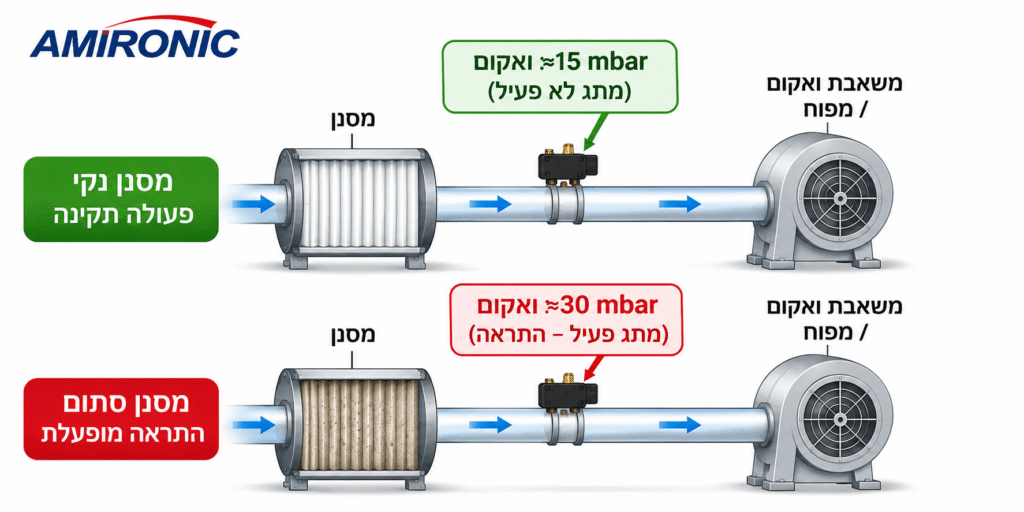
For example, consider a system where the normal vacuum level at the measurement point is 15 mbar, while a contaminated filter causes the vacuum level to increase to 30 mbar. In principle, a vacuum switch can be selected to provide an indication when an appropriate threshold is reached.

These values are provided for illustration only and do not represent the actual performance of any specific system.

It is important to emphasize that an increase in vacuum level does not necessarily indicate a clogged filter. It may also result from a blockage in the piping, a change in valve position, a change in blower speed, or other operating conditions.

Therefore, the measurement location and switching setpoint must be defined according to the characteristics of the system.

1.3 Vacuum Monitoring vs. Differential Pressure Measurement

One of the most important distinctions when designing a filter monitoring system is the difference between measuring vacuum at a single point and measuring differential pressure across the filter.

Vacuum Monitoring refers to measuring pressure at a specific location relative to a reference pressure, typically atmospheric pressure.

Differential Pressure Monitoring refers to measuring the pressure difference between the upstream and downstream sides of the filter.

The differential pressure is calculated as follows:

ΔP = P₁ − P₂

Where:

  • P₁ – Pressure upstream of the filter.

  • P₂ – Pressure downstream of the filter.

  • ΔP – Pressure drop across the filter (Differential Pressure).

As contaminants accumulate in the filter, the pressure drop across it may increase at a given flow rate.

Direct differential pressure measurement makes it possible to monitor the resistance created by the filter, while a single-point vacuum measurement provides an indirect indication that also depends on the system’s operating conditions.

Therefore, in systems with relatively stable flow conditions, a vacuum switch can provide an effective and cost-efficient solution for detecting filter clogging.

However, in systems with variable flow rates, changing blower speeds, or dynamic pressure conditions, direct differential pressure measurement or additional monitoring parameters may be required to reliably identify filter clogging.
2. The Physics of Filter Clogging – Understanding the Relationship Between Flow Rate, Vacuum and Pressure Drop

2.1 How Does a Filter Affect Airflow?

When air flows through a filter, it must pass through filter media containing pores or small passages. These passages allow air to flow while trapping particles and contaminants.

As air passes through the filter media, it encounters resistance to flow, resulting in a pressure difference between the filter inlet and outlet.

This pressure difference is known as the pressure drop.

In a clean filter, the pressure drop is relatively low compared to that of a contaminated filter, assuming the flow rate remains constant.

Over time, particles accumulate within the filter media, reducing the effective area available for airflow and increasing flow resistance.

As a result, a greater pressure difference is required to maintain the same airflow through the filter.

2.2 The Relationship Between Pressure Drop and Airflow

In fluid flow systems, pressure drop depends on several factors, including flow rate, passage geometry, air density, viscosity, and the characteristics of the filter media.

For illustration, this behavior can be described using an approximate relationship:

ΔP = K × Qⁿ

Where:

  • ΔP – Pressure drop across the filter.

  • K – A coefficient representing the filter’s resistance to flow.

  • Q – Airflow rate.

  • n – An exponent that depends on the flow characteristics and filter properties.

In simplified models, the value of n may range approximately between 1 and 2. However, actual system behavior should be evaluated using the filter manufacturer’s performance curves and the specific operating conditions.

As the filter becomes contaminated, the resistance coefficient K increases. Therefore, at a constant flow rate, the pressure drop also increases.

However, in a system equipped with a blower or pump operating at a fixed speed, the airflow rate itself may change as filter resistance increases.

For this reason, effective filter monitoring requires an understanding of the behavior of the entire system, not just the filter.

2.3 What Happens to the Vacuum Level When a Filter Becomes Clogged?

Consider a suction system in which air enters from the surrounding environment, passes through a filter, and continues toward a blower or vacuum pump.

When the filter is clean, its resistance to airflow is relatively low, and the system operates at its intended operating point.

As the filter becomes clogged, flow resistance increases. In certain systems, this causes the pressure in the line between the filter and the blower to decrease, resulting in a higher vacuum level at that measurement point.

For example:

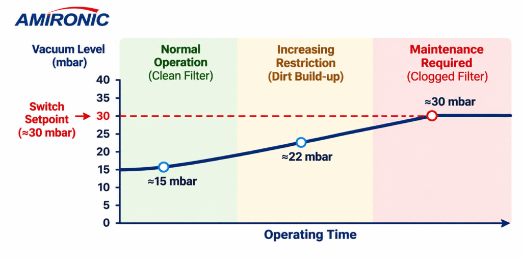
Filter Condition Example Vacuum Level Alarm Status
Clean filter 15 mbar No alarm
Contaminant buildup 22 mbar Monitoring
Clogged filter 30 mbar Alarm activated

The values shown in this table are provided for engineering illustration only and do not represent measurements from an actual system.

In such a system, a vacuum switch configured with an appropriate setpoint can detect the increase in vacuum level and activate an alarm.

However, this behavior is not universal. In systems with flow control, variable-speed operation, or changing loads, the relationship between filter condition and vacuum level may be different.

2.4 Why Is Vacuum Switch Location Important?

The installation location of a vacuum switch directly affects the meaning of the measurement.

When the switch is installed between the filter and the vacuum pump, it measures the vacuum level on the downstream side of the filter.

In a system where the filter inlet is exposed to stable atmospheric pressure, changes in the downstream vacuum level may provide an indication of changes in the pressure drop across the filter.

However, when the pressure at the filter inlet also varies, a single-point measurement may not be sufficient to determine whether the filter is clogged.

For example, changes in inlet pressure, piping restrictions, or pump operating conditions may affect the measured vacuum level even when the filter itself is functioning properly.

Engineering rule of thumb: When suction conditions and flow rates are relatively stable, single-point vacuum monitoring can provide a simple solution for detecting filter clogging. When operating conditions vary significantly, direct differential pressure measurement should be considered.

2.5 How Do You Define an Appropriate Alarm Threshold?

Selecting the correct alarm threshold is one of the most important steps when designing a filter monitoring system.

A threshold that is too low may cause false alarms, while a threshold that is too high may result in late detection of a clogged filter.

Therefore, the switching setpoint should be determined based on several parameters:

  • Vacuum level with a new, clean filter.

  • Vacuum levels throughout the normal operating range.

  • Pressure variations caused by changes in flow rate or load.

  • Maximum allowable pressure drop specified by the filter manufacturer.

  • Switching setpoint accuracy, repeatability, and hysteresis.

  • Effects of temperature and environmental conditions.

For example, if the normal vacuum level ranges from 10 to 18 mbar, while a filter approaching the end of its service life causes the vacuum level to increase to 35 mbar, an alarm threshold between these operating ranges may be considered.

However, the switch’s operating range and setpoint tolerance must be suitable for the difference between normal and abnormal operating conditions.

In mechanical switches, the actual switching point may differ from the nominal value due to manufacturing tolerances, temperature, and operating conditions.

Therefore, in applications requiring high reliability, calibration or verification testing under actual operating conditions is recommended.

3. Vacuum Switch vs. Continuous Pressure Sensor – When Is Each Solution Required?

Not every filter monitoring system requires a digital pressure sensor or a complex control system.

In many applications, the most important information is not the exact pressure value at every moment, but whether the system has crossed a threshold that requires attention.

3.1 Vacuum Switch – A Solution for Threshold Monitoring

A vacuum switch generates an electrical signal when the pressure reaches a predefined switching setpoint.

This signal can be used to activate an alarm, provide an operator indication, connect to a PLC digital input, or trigger a protective mechanism.

Potential advantages include:

  • Relatively simple construction.

  • Direct connection to a control circuit.

  • No need for continuous measurement processing.

  • Suitability for OEM systems and industrial equipment.

  • Ability to trigger an alarm without complex monitoring software.

A vacuum switch is particularly suitable when the main question is:

Has the vacuum level exceeded the allowable threshold?

3.2 Continuous Pressure Sensor – A Solution for Trend Monitoring

An analog or digital pressure sensor provides continuous pressure measurements.

These measurements allow system behavior to be recorded over time, trends to be identified, graphs to be generated, and more advanced analysis of filter condition to be performed.

This solution is particularly suitable when the application requires:

  • Continuous monitoring of pressure changes.

  • Trend analysis over time.

  • Comparison of data between operating cycles.

  • Calculation of the rate at which filter clogging develops.

  • Integration with condition-based maintenance systems.

3.3 Can a Vacuum Switch Support Predictive Maintenance?

It is important to distinguish between three maintenance approaches:

Preventive Maintenance – Replacing a filter according to a predetermined time interval or number of operating hours.

Condition-Based Maintenance – Performing maintenance based on an indication of the equipment’s actual condition, such as a vacuum threshold being exceeded.

Predictive Maintenance – Using data and trend analysis to estimate when a failure may occur or when maintenance will be required.

A standalone vacuum switch generally provides a threshold indication. Therefore, it is primarily suited to condition-based maintenance.

However, the switching signal can be integrated into a control system that records events over time.

For example, a PLC can record the number of vacuum alarm events, their duration, and the number of operating hours since the last filter replacement.

Analyzing this information, together with additional operating data, may help identify trends and provide an earlier indication of maintenance requirements.

In this way, a simple switching component can become part of a more advanced monitoring and maintenance system, without presenting it as a continuous pressure sensor.

4. HERGA Vacuum Switches – Solutions for Filter Monitoring and Suction Systems

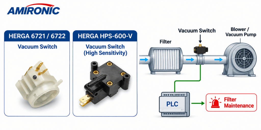
HERGA Technology offers a range of vacuum switches designed for OEM applications, suction systems, industrial equipment, and control systems where pressure changes need to be detected.

Two product families particularly relevant to vacuum monitoring applications are:

  • HERGA 6721/6722 – Electromechanical vacuum switches offering multiple operating ranges, contact options, and connection configurations.

  • HERGA HPS-600-V / HPS-601-V – Compact, high-sensitivity vacuum switches with factory-set or adjustable switching setpoints.

Both product families convert pressure changes into electrical switching signals. However, they differ in their operating ranges, electrical characteristics, dimensions, and application-specific configuration options.

It is important to note that these switches measure the vacuum level at their connection point. They do not directly measure the pressure difference between the upstream and downstream sides of a filter. Therefore, their suitability for detecting filter clogging depends on the overall system design.

4.1 HERGA 6721/6722 – Vacuum Switches for Industrial Systems

The HERGA 6721/6722 series is primarily designed for Original Equipment Manufacturers (OEMs) requiring reliable vacuum switches with various configuration options.

The series includes models with different vacuum operating ranges, allowing engineers to select a switch according to the pressure level at which switching is required.

Examples of available models and their operating ranges:

Model Vacuum Operating Range
6721-03 7.5–20 mbar
6721-06 17.5–37 mbar
6721-20 32–80 mbar
6721-30 70–200 mbar
6721-40 185–670 mbar

These operating ranges allow the switches to be integrated into systems operating at different vacuum levels, from applications sensitive to relatively small pressure changes to systems operating at higher vacuum levels.

For example, in a filtration system requiring an alarm when the vacuum level reaches approximately 30 mbar, the HERGA 6721-06, with its operating range of 17.5–37 mbar, may be considered.

However, the final model selection must account for switching setpoint tolerance, operating conditions, and electrical requirements.

Key technical characteristics include:

  • Operating temperature: -5°C to +70°C.

  • Housing material: Thermoplastic.

  • Diaphragm material: Neoprene in the specified models.

  • Weight: Approximately 40 g.

  • Setpoint setting accuracy: ±10%.

  • Connection options including a 4 mm hose connection and threaded connections, depending on configuration.

  • Various microswitch and electrical contact options.

  • UL 508 approved versions available for selected models only.

The 6721 series features a Single Pole Changeover (SPCO) contact configuration, while the 6722 series offers double-pole switching.

The double-pole switching option may be useful when two electrical circuits need to be controlled by the same pressure event, subject to the selected model’s configuration and electrical requirements.

HERGA also offers gold-plated contact options for applications involving very low electrical currents, depending on the requested configuration.

4.2 HERGA HPS-600-V – High-Sensitivity Vacuum Switch

The HPS-600-V series is designed for applications requiring high sensitivity to vacuum changes, combined with a compact construction suitable for integration into OEM equipment.

The switches are available in several operating ranges:

Range Vacuum Operating Range
Range A 5–20 mbar
Range B 20–37 mbar
Range C 37–189 mbar
Range D 189–964 mbar

The ability to select an operating range according to the application is particularly important in filtration systems where the difference between normal and abnormal operating conditions may involve a relatively small change in vacuum level.

For example, in a system where the normal vacuum level is 8 mbar and contaminant accumulation causes it to increase to approximately 17 mbar, a switch from Range A may be considered.

However, the specified switching setpoint tolerance for this series is ±20%. Therefore, engineers must verify whether the selected switch can reliably distinguish between the required operating conditions.

Key technical characteristics include:

  • Overall operating range of the series: 5–964 mbar, depending on the model.

  • Factory-set or adjustable switching setpoint options.

  • SPDT (Single Pole Double Throw) contact configuration.

  • Standard current ratings of 3A, 5A, 10A, or 15A, depending on the operating range.

  • Gold contact options for low-current applications, rated at 0.1A.

  • Specified mechanical life of 10 million cycles.

  • Standard operating temperature: +4°C to +65°C.

  • Extended temperature requirements may be discussed with the manufacturer.

  • UL 508 approval, as specified in the manufacturer’s datasheet.

One of the notable advantages of this series is its compact construction, allowing the vacuum switch to be integrated into systems where installation space is limited.

In OEM equipment, where the switch may be installed inside the machine enclosure or near the suction piping, component dimensions and mounting options can be important design considerations.

4.3 Comparison: HERGA 6721/6722 vs. HPS-600-V

Feature HERGA 6721/6722 HERGA HPS-600-V
Overall vacuum range of listed models 7.5–670 mbar 5–964 mbar
Setpoint accuracy/tolerance ±10% ±20%
Operating temperature -5°C to +70°C +4°C to +65°C
Switching configuration Single pole; double-pole option with 6722 SPDT
Mechanical life 1–2 million cycles, depending on model 10 million cycles
Gold contacts Available upon request GOLD versions available
UL 508 approval Selected models Specified in datasheet

The specifications are based on HERGA datasheets dated April 2024 and June 2025.

It is important to understand that the overall vacuum range of each product family does not represent the adjustment range of every individual model. The appropriate operating range must be selected first, followed by the required electrical and mechanical configuration.

4.4 How to Choose Between the Two Product Families

Selecting between HERGA 6721/6722 and HPS-600-V vacuum switches involves more than comparing vacuum operating ranges.

Engineers must also consider system characteristics, switching requirements, and installation conditions.

When sensitivity to particularly low vacuum levels is required, the HPS-600-V Range A may be considered, as its operating range starts at 5 mbar.

When double-pole switching is required, the 6722 series may be suitable, depending on the available configurations.

When a particularly long mechanical service life is required, the specified 10 million mechanical cycles of the HPS-600-V series may offer an advantage, subject to operating conditions and electrical life requirements.

For systems operating at low temperatures, the standard operating temperature range of the 6721/6722 series may be more suitable, as it extends down to -5°C, compared with +4°C for the HPS-600-V series.

In all cases, the final selection should be based on the manufacturer’s specifications and verification of suitability for the actual application.

5. Integrating a Vacuum Switch into PLC-Based Monitoring and Maintenance Systems

One of the significant advantages of an electromechanical vacuum switch is its ability to integrate into an industrial control system using a simple switching signal.

Instead of installing a continuous pressure sensor, signal converter, and data processing system, it is often possible to connect the switch contacts directly to a PLC digital input.

5.1 Operating Principle

In a typical system, the vacuum switch is installed in the suction line downstream of the filter, at a location selected according to the system design.

When the vacuum level is within the normal operating range, the switch contacts remain in their designated normal operating state.

When the vacuum level crosses the switching setpoint, the contact state changes.

The PLC detects this change and can perform a programmed action, such as:

  • Activating a warning indicator on the control panel.

  • Displaying a “Filter Maintenance Required” message.

  • Recording an event in the fault log.

  • Sending an alarm to an HMI or SCADA system.

  • Stopping the machine when equipment protection is required.

The appropriate response depends on the severity of the condition and the process requirements.

5.2 Preventing False Alarms

In suction systems, vacuum levels are not necessarily completely stable.

Blower startup, valve opening, load changes, or airflow fluctuations may cause temporary pressure variations.

If the control system responds to every momentary change in the switch contact state, false alarms may occur.

One way to address this is to implement an alarm validation delay in the PLC software.

For example, the PLC can be programmed to activate a clogged-filter alarm only if the vacuum switch remains in its alarm state for five consecutive seconds.

This approach helps reduce unnecessary responses to short-term pressure fluctuations that do not necessarily indicate filter clogging.

The validation delay should be selected according to the system dynamics and the required response time.

5.3 Hysteresis and Prevention of Repeated Switching

Hysteresis is the difference between the pressure at which a switch changes state in one direction and the pressure at which it returns to its previous state.

For example, a vacuum switch may enter its alarm state when the vacuum level rises above a certain threshold and return to its normal state only after the vacuum level falls below a lower value.

Hysteresis helps prevent rapid, repeated switching when the pressure fluctuates near the switching setpoint.

It is important to distinguish between the mechanical hysteresis of the switch and a logical delay implemented in the PLC. These are two different mechanisms, and they can be combined when appropriate.

When selecting a HERGA vacuum switch, engineers should review the operating and release pressure characteristics of the required configuration. The hysteresis value should not be inferred solely from the switching setpoint tolerance.

5.4 From Simple Alarm Monitoring to Data-Driven Maintenance

Even when a vacuum switch provides only a binary signal, the control system can extract useful information from it.

For example, the PLC can record:

  • Number of alarm events per shift.

  • Total time the system operates in an alarm condition.

  • Operating hours since the last filter replacement.

  • Frequency of alarm events relative to operating cycles.

  • Changes in alarm frequency throughout the filter’s service life.

Analyzing this information may help maintenance teams identify deteriorating operating conditions and improve filter replacement planning.

However, binary signals alone do not provide continuous measurements of filter condition. For more accurate prediction, additional parameters such as flow rate, pressure, operating hours, or other process data may need to be incorporated.

6. Engineering Case Study – Monitoring Filter Clogging in an Industrial Suction System Using HERGA HPS-600-V

6.1 System Description and Engineering Challenge

Consider an industrial suction system designed to remove dust and particles from an automated manufacturing process.

The system consists of an electric blower, an air filter, suction piping, and a PLC that controls machine operation.

The filter is designed to prevent particles from reaching the blower and other sensitive system components.

During operation, dust and particles accumulate within the filter media. As contamination increases, the filter’s resistance to airflow also increases.

As a result, under certain operating conditions, the vacuum level in the piping between the filter and the blower may rise.

When the filter becomes significantly clogged, several problems may occur:

  • Reduced airflow and suction efficiency.

  • Reduced ability to remove particles from the manufacturing process.

  • Changes in the blower’s operating point.

  • Increased loading on system components, depending on the blower characteristics.

  • The need to stop the machine for filter cleaning or replacement.

In the original system, filters are replaced according to a fixed maintenance schedule, without direct information about their actual condition.

This approach may result in premature replacement of filters that are still functional or continued operation with a clogged filter.

The engineering objective is to detect changes in suction conditions and generate an alarm when inspection or maintenance is required.

6.2 Defining the System Requirements

For this example, assume that the following values were obtained during system testing:

Parameter Example Value
Vacuum level with a clean filter 12 mbar
Vacuum level during normal operation 12–18 mbar
Vacuum level with a contaminated filter 25 mbar
Vacuum level requiring inspection 30 mbar
PLC digital input voltage 24 VDC
Required action Maintenance alarm

These values are provided for engineering illustration only. They do not represent an actual installation or HERGA test results.

In this case, the objective is to select a vacuum switch capable of detecting a threshold crossing at approximately 30 mbar and transmitting a signal to the PLC.

6.3 Selecting a Suitable Vacuum Switch

One product that may be considered for this application is the HERGA HPS-600-V Range B.

According to the manufacturer’s datasheet, this version has an operating range of 20–37 mbar.

Key specifications include:

  • Vacuum operating range: 20–37 mbar.

  • Switching setpoint tolerance: ±20%.

  • Contact configuration: SPDT.

  • Standard current rating for Range B: Up to 5A, depending on voltage and specified load conditions.

  • Standard operating temperature: +4°C to +65°C.

  • Specified mechanical life: 10 million cycles.

The operating range allows a nominal switching setpoint of approximately 30 mbar to be considered.

However, a tolerance of ±20% means that not every switch can be assumed to operate at exactly 30 mbar.

If the tolerance is interpreted relative to a nominal switching setpoint of 30 mbar, a 20% deviation corresponds to 6 mbar. Therefore, without additional calibration or verification, the possibility of switching at values different from the nominal setpoint must be considered.

This means that in systems where the difference between normal and abnormal operating conditions is relatively small, switching setpoint tolerance may become a critical selection factor.

Engineers must ensure that the selected switch does not generate false alarms during normal operation while also avoiding excessively delayed detection of abnormal conditions.

6.4 Integrating the Switch into the Control System

The vacuum switch is installed in the suction line downstream of the filter, at a location where changes in vacuum level provide a meaningful indication of system behavior.

The switch contacts are connected to a PLC digital input.

During normal operation, the vacuum level remains below the selected threshold, and the system continues operating normally.

As the filter becomes contaminated and the vacuum level increases, the switch changes its contact state when the actual switching setpoint is crossed.

The PLC detects this change and activates a maintenance alarm.

For example:

Filter Maintenance Required – Check Air Filter

A delay of several seconds can be configured in the PLC to prevent alarms caused by momentary pressure fluctuations.

In addition, the event log can record the time of the alarm and the number of operating hours since the last filter replacement.

In systems requiring high availability, the control logic can be configured to allow continued operation following an initial warning, while a prolonged alarm condition or a combination of additional abnormal conditions may trigger a machine shutdown.

6.5 Expected Engineering Benefits

Integrating a suitable vacuum switch may enable a transition from maintenance based on fixed time intervals to maintenance based on actual operating conditions.

Potential benefits include:

  • Early detection of abnormal changes in suction conditions.

  • Reduced risk of continued operation with a clogged filter.

  • More efficient planning of filter replacement.

  • Fewer unnecessary replacements when the filter is still functional.

  • Improved machine availability through maintenance alerts.

  • Relatively straightforward integration into an existing PLC system.

It is important to emphasize that this is an illustrative engineering case study, not a description of an actual installation or experimental results.

Successful implementation depends on selecting the correct measurement location, defining an appropriate switching setpoint, and verifying system behavior under actual operating conditions.

7. Engineering Rules of Thumb for Selecting a Vacuum Switch for Filter Monitoring

Selecting a vacuum switch involves more than matching the required pressure range. Engineers must also consider system characteristics, environmental conditions, electrical requirements, and the consequences of false or delayed alarms.

7.1 Define Vacuum Levels Under Normal and Abnormal Conditions

Before selecting a vacuum switch, it is recommended to measure vacuum levels under several operating conditions.

The system should be evaluated with a clean filter, during normal operation, and when the filter reaches its maximum allowable flow resistance.

These tests should be performed under the relevant flow and load conditions.

The greater the difference between normal vacuum levels and the alarm threshold, the easier it is to select a switch with a suitable switching setpoint.

7.2 Do Not Confuse Vacuum with Differential Pressure

A vacuum switch measures pressure at a single connection point relative to its reference pressure.

It does not directly measure the pressure drop across the filter.

When the filter inlet pressure is stable and flow conditions are known, vacuum measurement may provide a useful indication of filter clogging.

However, when inlet conditions and flow rates vary significantly, a dedicated differential pressure sensor or differential pressure switch should be considered.

7.3 Select an Operating Range Suitable for the Required Threshold

A switch should not be selected simply because the overall operating range of its product family includes the required pressure.

The specific model must support the desired switching setpoint.

For example, the HERGA HPS-600-V series offers four operating ranges, from 5–20 mbar to 189–964 mbar.

Selecting the appropriate range helps ensure that the switch is suitable for the application’s requirements.

7.4 Check the Switching Setpoint Tolerance

Switching setpoint tolerance affects how accurately a threshold crossing can be detected.

According to HERGA datasheets:

  • The 6721/6722 series specifies a setpoint setting accuracy of ±10%.

  • The HPS-600-V series specifies a switching setpoint tolerance of ±20%.

The significance of these tolerances must be evaluated in relation to the difference between normal operating conditions and conditions requiring an alarm.

When a particularly precise switching threshold is required, calibration options or alternative measurement solutions should be considered.

7.5 Match the Electrical Contacts to the Control System

A vacuum switch may be connected directly to a control circuit, a PLC digital input, or a relay control circuit.

Operating voltage, current, load type, and contact configuration must be verified.

In control applications involving very low currents, gold-plated contacts may offer improved switching reliability.

However, the electrical rating of the gold-contact version must be suitable for the intended application.

7.6 Consider Temperature and Environmental Conditions

Operating temperature may affect switch characteristics and the switching setpoint.

The specified temperature range must be suitable for the environment in which the switch is installed.

Compatibility with exposure to moisture, dust, vibration, and chemicals should also be evaluated.

A vacuum switch should not automatically be assumed suitable for wet or dusty environments simply because it is intended for use in a suction system.

7.7 Verify Material Compatibility with the Process Medium

In systems where the switch is exposed to air containing vapors, oils, chemicals, or contaminants, the compatibility of the switch materials with the process medium must be verified.

The HERGA 6721/6722 series offers different diaphragm and spring material options, depending on the application requirements.

It is also important to consider that, in the models described in the datasheet, the spring is located within the vacuum chamber and is exposed to the process medium.

Chemical compatibility should be evaluated based on the manufacturer’s specifications and actual operating conditions.

7.8 Define What Happens When the Switch Is Activated

A vacuum switch provides a switching signal, but determining how the system responds to that signal is part of the overall control system design.

In some applications, an operator warning is sufficient.

In others, continued operation with a clogged filter may cause equipment damage, making a system shutdown necessary.

The required response, alarm reset conditions, and handling of potential control circuit faults should be defined in advance.

8. Common Mistakes When Designing Filter Clogging Monitoring Systems

8.1 Selecting a Switch Based Only on Nominal Pressure

One common mistake is selecting a vacuum switch based solely on its nominal switching setpoint, without considering tolerances and operating conditions.

A switch specified to operate at approximately 30 mbar will not necessarily switch at exactly that pressure.

For example, in a system where it is necessary to distinguish between 25 and 30 mbar, a wide switching tolerance may compromise detection reliability.

8.2 Installing the Switch at an Unsuitable Measurement Point

The location of the vacuum switch affects both the measured pressure and its significance.

Installing the switch at a location subject to significant pressure fluctuations, local flow effects, or pressure changes unrelated to the filter may generate alarms that do not accurately reflect filter condition.

Therefore, it is recommended to select a measurement point that represents the relevant suction conditions and ensure that the pneumatic connection itself does not become clogged.

8.3 Ignoring Changes in Flow Rate

When airflow changes, the pressure drop across the filter may also change.

Therefore, an increase in vacuum level does not necessarily indicate filter clogging.

In systems with variable flow rates, engineers should determine whether pressure changes caused by normal operating conditions can be distinguished from those caused by contaminant accumulation.

8.4 Using a Vacuum Switch When Continuous Measurement Is Required

A vacuum switch provides information about threshold crossings but does not continuously measure pressure.

When an application requires trend monitoring, calculation of clogging rates, or estimation of remaining filter service life, a continuous pressure sensor may be more suitable.

In some applications, both solutions can be combined.

8.5 Ignoring System Behavior During Startup

Temporary pressure fluctuations may occur during blower or vacuum pump startup.

If the vacuum switch is connected directly to an alarm system without an appropriate validation mechanism, false alarms may occur.

This can be minimized by selecting an appropriate switching threshold, evaluating hysteresis, and implementing a logical delay in the controller.

9. Conclusion – Simple Monitoring That Can Prevent Costly Failures

Filters are essential components in suction systems, vacuum pumps, HVAC equipment, and industrial machinery.

Despite their seemingly simple function, contaminant accumulation within a filter can affect airflow, pressure conditions, and overall system performance.

A vacuum switch detects changes in vacuum level and generates an electrical switching signal when a predefined threshold is crossed.

By selecting the correct measurement location and switching setpoint, a vacuum switch can be used to identify abnormal operating conditions that may indicate filter clogging.

The HERGA 6721/6722 and HPS-600-V product families offer a variety of operating ranges, switching configurations, and customization options for OEM systems and industrial equipment.

Vacuum switches are particularly suitable when a simple indication of a pressure threshold crossing is required, without the need for continuous measurement.

Integrating the switch into a PLC allows operators to generate alarms, record events, and implement maintenance actions based on actual operating conditions.

However, it is important to remember that measuring vacuum at a single point is not equivalent to directly measuring differential pressure across a filter.

In systems with significantly varying flow conditions, or where advanced trend analysis is required, continuous pressure measurement or dedicated differential pressure monitoring may be necessary.

Selecting the right vacuum switch begins not with a part number, but with understanding system behavior, flow conditions, and the pressure threshold at which action is required.

Amironic, the official representative of HERGA Technology in Israel, assists equipment manufacturers and engineers in selecting vacuum switches, pressure switches, and switching solutions suited to their application requirements.

10. Frequently Asked Questions – FAQ

What Is a Vacuum Switch?

A vacuum switch is an electromechanical device that changes the state of its electrical contacts when the vacuum level reaches a predefined threshold. It is used to detect pressure conditions and activate alarms or control functions in suction systems, vacuum pumps, and industrial equipment.

How Can a Vacuum Switch Detect a Clogged Filter?

As contaminants accumulate in a filter, its resistance to airflow increases. In certain suction systems, this causes the vacuum level downstream of the filter to rise. A vacuum switch installed at an appropriate location can detect when a threshold is crossed and activate an alarm. However, engineers must verify that the pressure change reflects filter condition rather than other changes in operating conditions.

What Is the Difference Between a Vacuum Switch and a Differential Pressure Switch?

A vacuum switch measures pressure at a single point relative to a reference pressure, typically atmospheric pressure. A differential pressure switch measures the pressure difference between two points. For directly monitoring pressure drop across a filter, a differential pressure switch may be more suitable.

Can a Vacuum Switch Replace a Pressure Sensor?

When the only requirement is to detect a threshold crossing, a vacuum switch may eliminate the need for a continuous pressure sensor. However, when accurate measurements over time, trend analysis, or filter condition prediction are required, a continuous pressure sensor may be more appropriate.

What Is the Difference Between HERGA 6721 and HERGA 6722?

The HERGA 6721 series offers single-pole switching configurations, while the 6722 series provides a double-pole switching option. Selection depends on the electrical circuit requirements and the required switch configuration.

What Is the Operating Range of the HERGA HPS-600-V?

The HPS-600-V series offers four vacuum operating ranges: 5–20 mbar, 20–37 mbar, 37–189 mbar, and 189–964 mbar. The appropriate range should be selected according to the required switching setpoint.

Can the Switching Setpoint of the HPS-600-V Be Adjusted?

Yes. According to HERGA’s datasheet, the series is available with either factory-set or adjustable switching setpoints. The adjustment capability of the ordered configuration and its switching setpoint tolerance should be verified.

Can a Vacuum Switch Be Connected Directly to a PLC?

Yes. The switch contacts can be connected to a PLC digital input, provided that the electrical characteristics of the switch and the input are compatible. Operating voltage, current, and contact configuration must be checked.

Is a Vacuum Switch Suitable for Predictive Maintenance?

A vacuum switch is primarily suitable for threshold monitoring and condition-based maintenance. When switching signals are combined with additional operating data and trend analysis, the information can contribute to a predictive maintenance system.

Can a Vacuum Switch Detect Every Type of Blockage?

Not necessarily. The switch detects pressure changes, not their underlying causes. Filter clogging, piping restrictions, changes in valve position, or changes in pump operating conditions may all affect vacuum levels. Therefore, the monitoring method must be matched to the system design.

What Is the Difference Between Silver Contacts and Gold Contacts in a Vacuum Switch?

Silver contacts are suitable for a variety of electrical switching applications, according to the switch’s electrical ratings. Gold-plated contacts may be particularly suitable for very low-current control circuits where high contact reliability is required. Contact material should be selected according to voltage, current, and operating conditions.

How Can False Alarms Be Reduced in a Filter Monitoring System?

False alarms can be reduced by selecting an appropriate measurement location, defining a suitable switching threshold, considering hysteresis, and implementing an alarm validation delay in the controller software. System behavior during startup and load changes should also be evaluated.

11. Glossary of Technical Terms

Vacuum Switch

A device that changes the state of its electrical contacts when the vacuum level reaches a predefined threshold.

Vacuum Level

The difference between a reference pressure, typically atmospheric pressure, and the pressure measured at a specific point when the measured pressure is below the reference pressure.

Differential Pressure

The pressure difference between two points in a system. In filter monitoring applications, this generally refers to the difference between the upstream and downstream pressures of the filter.

Pressure Drop

The reduction in pressure that occurs when a fluid flows through a component that creates resistance to flow, such as a filter, valve, or piping.

Filter Clogging

The accumulation of particles and contaminants within filter media, potentially increasing the filter’s resistance to flow.

Flow Rate

The quantity of liquid or gas passing through a system per unit of time. Volumetric airflow is commonly measured in units such as m³/h or L/min.

Setpoint

The pressure value at which a switch is intended to change the state of its electrical contacts.

Setpoint Tolerance

The allowable deviation between the nominal switching setpoint and the actual switching point, according to the manufacturer’s specifications.

Hysteresis

The difference between the switching point in one direction and the reset point in the opposite direction. Hysteresis helps prevent repeated switching when pressure fluctuates near the threshold.

Repeatability

The ability of a switch to operate repeatedly at approximately the same pressure under identical test conditions.

SPDT – Single Pole Double Throw

An electrical changeover contact configuration that allows a common contact to switch between two alternative contacts.

SPCO – Single Pole Changeover

A term describing a single-pole changeover contact, similar to an SPDT configuration.

PLC – Programmable Logic Controller

An industrial controller used to control, monitor, and automate machinery and industrial processes.

OEM – Original Equipment Manufacturer

A manufacturer that integrates components and assemblies into equipment or systems it designs and produces.

Condition-Based Maintenance

A maintenance approach in which service activities are performed based on information about the equipment’s actual condition rather than relying solely on fixed maintenance intervals.

Predictive Maintenance

A maintenance approach that uses data, trend analysis, and sometimes computational models to estimate when maintenance may be required or when a failure is likely to occur.

Proof Pressure

A test pressure that a component is designed to withstand, according to the manufacturer’s definition, without permanent damage under specified test conditions. It should not be interpreted as the maximum allowable continuous operating pressure.

Diaphragm

A flexible membrane that responds to pressure differences and converts pressure changes into mechanical movement within a switching mechanism.

Gold Contacts

Gold-plated electrical contacts designed, among other purposes, to improve switching reliability in low-current circuits, subject to the switch design and electrical ratings.

HERGA Vacuum Switch Solutions in Israel – Amironic

Amironic is the official representative of HERGA Technology in Israel, offering switching and control solutions for a wide range of industrial applications.

Available solutions include vacuum switches, pressure switches, pneumatic switches, footswitches, and customized switching solutions for Original Equipment Manufacturers (OEMs).

When selecting a vacuum switch for filter monitoring, it is recommended to define the normal vacuum level, required alarm threshold, environmental conditions, and electrical requirements in advance.

The Amironic team assists engineers and equipment manufacturers in evaluating HERGA vacuum switches for specific applications, selecting the appropriate operating range, and defining the required configuration.

For additional information and technical assistance:

Amironic Ltd. – www.amironic.co.il

Tags: Herga

Related Articles

Don’t Design a New Footswitch – Build It from a Modular Platform

26/07/2026amironicLTD

Pneumatic Foot Bellows vs. Electrical Footswitch – Do You Really Need to Run Electricity to the Foot Pedal?

06/07/2026amironicLTD

Medical Footswitch Solutions for Urology Devices

16/12/2025amironicLTD

Recent Posts

  • How to Choose a High-Precision IMU for GPS-Denied Navigation: An Engineering Guide Featuring Gladiator Technologies
  • Vacuum Switches for Filter Monitoring – Clog Detection, Differential Pressure and Predictive Maintenance
  • Hook Terminal vs. Screw Terminal – Understanding Terminal Connections in AIRPAX Hydraulic Magnetic Circuit Breakers
  • Hermetic Sealing in Inertial Sensors – What Is the Difference Between IP67 and MIL-STD-883?
  • Pneumatic Switches for Wet Environments – Operating Principles, Electrical Separation, and Applications in Pools, Spas, and Humid Environments

Categories

  • Air Switch
  • Circuit Breakers
  • Elapsed Time Indicator
  • Feedthrough
  • Footswitches
  • Gears & Transmission
  • Hour Meters
  • Infra Red Switches
  • INFRARED LAMPS
  • Low Noise Inertial MEMS
  • Mechanics
  • MEMS Gyroscope
  • MEMS Inertial
  • Microelectronics
  • Motors
  • Position Sensors
  • Power Supply
  • Pressure Sensors
  • Pressure Switch
  • Sealing
  • Switches
  • Temperature Sensors
  • Tungsten and Molybdenum
  • Uncategorized
  • Vacuum Switches

Quick Contact

Fill out the form and our representatives will return to you

    Name (required)

    Email (required)

    Phone

    Message

    This site is protected by reCAPTCHA and the Google
    Privacy Policy and
    Terms of Service apply.

    Amironic Ltd.

    3 Rabinovich Street, Petah Tikva 4928144 , Israel. Tel: +972-3-9047744 E-mail: office@amironic.co.il
    Email
    Facebook
    Twitter
    LinkedIn
    YouTube
    Press on the ISO Certificate below for download
    ISO 9001:2015 Certification
    • MEMS Inertial
    • Circuit Breakers
    • Footswitches
    • Mechanical & Transmissions
    • Sensors
    • Motors
    • Electronics
    • Hand Control
    • Power Solutions

    News

    • How to Choose a High-Precision IMU for GPS-Denied Navigation: An Engineering Guide Featuring Gladiator Technologies
    • Vacuum Switches for Filter Monitoring – Clog Detection, Differential Pressure and Predictive Maintenance
    • Hook Terminal vs. Screw Terminal – Understanding Terminal Connections in AIRPAX Hydraulic Magnetic Circuit Breakers
    • Hermetic Sealing in Inertial Sensors – What Is the Difference Between IP67 and MIL-STD-883?
    • Pneumatic Switches for Wet Environments – Operating Principles, Electrical Separation, and Applications in Pools, Spas, and Humid Environments
    About AmironicContactעברית
    © 2022 Amironic All rights reserved. All Trademarks are the property of their respective owners.
    • Increase Font
    • Decrease Font
    • Black & White
    • Inverse Colors
    • Highlight Links
    • Regular Font
    • Reset