flagעברית
flagEnglish
3 Rabinovich St., Petah-Tikva, Israel
+972 3 9047744
office@amironic.co.il
Facebook
Twitter
LinkedIn
YouTube
  • Products
    • MEMS Inertial
      • Gyros & Accels
      • IMU
      • Inertial Navigation
      • AHRS
    • Circuit Breakers
      • Airpax Circuit Breakers
      • Electronic Circuit Breakers
      • Aircraft Circuit Breakers
      • Thermal Circuit Breakers
      • Sealing Solutions & Guards
    • Footswitches
      • Pedals & Bellows
      • USB
      • Air Switches
      • Medical
      • Modular Bases System
      • Industrial
      • Foot Potentiometers
      • Wireless
    • Mechanical & Transmisions
      • Gears
      • Sealing Solutions
      • Gearboxes
      • Couplings
      • Shafts & Bearings
      • Fasteners
      • Mechanical & Springs
      • Linear Motion
      • Anti-Vibration
    • Sensors
      • Thermostats
      • Temperature
      • Position
      • Pressure
      • Speed
      • Level Sensor
      • Load Cells
      • Flex Sensors
      • Membrane Potentiometer
    • Motors
      • Geared DC
      • Brushless DC
      • Step Motors with Gearbox
      • Torque Motors & Brushless Servo
      • DC Motors
    • Electronics
      • Xenon & IR Lamps
      • Counters & Meters
      • Microelectronics Packaging
      • Waterproof Switches
      • Micro Switches
    • Hand Control
      • Operator Controls (JOYSTICK)
      • Electrical
      • Pneumatic (Medical)
      • USB Hand Control
      • Air Push Button
      • Pressure Switch
      • IR Switch
    • Power Solutions
      • Rugged & Military Power Supply
      • Input Power Protection
      • Sealed Military Power Adaptor
      • Triple Output Military Power Supply Series – up to 250 W
    • Materials
      • Molybdenum and Advanced Alloys (TZM, MOLA, HCT)
      • Tungsten (Wolfram) and Advanced Alloys – High-Performance Materials for Extreme Conditions
      • Materials for Gears
  • Shop
  • Companies
  • About Amironic
  • News
  • Contact
Product was added to your cart

Cart

waze

Fighter Aircraft Without a Pilot: How Do You Build a Nervous System for an Aircraft That Must Make Its Own Decisions?

MEMS Inertial, Position Sensors, Power Supply, Temperature Sensors17/08/2026amironicLTD

From Edge AI and GPS-Denied Navigation to Tactical IMUs, Position Sensors and Temperature Sensors – The Engineering Challenges Behind the Next Generation of Autonomous Combat Aircraft

For decades, discussions about advanced fighter aircraft focused on their engines, radar, weapons, stealth and aerodynamic performance.

But the next generation of combat aircraft introduces another variable that changes almost the entire architecture:

There may be no pilot in the cockpit.

That does not mean simply removing the ejection seat, closing the canopy and connecting a remote control.

An unmanned combat aircraft required to operate autonomously or semi-autonomously must perform some of the functions currently handled by pilots and ground crews: understand the state of the aircraft, monitor the mission, detect changes in its environment, respond to failures and changing operational conditions, and maintain the ability to operate even when communication with the operator is limited.

This represents a significant transition from Automation to Autonomy.

An automated system can receive a predefined route and execute it. An autonomous system must receive information from its sensors, understand how conditions have changed, and adapt its behavior according to the mission parameters.

This distinction becomes particularly important on the modern battlefield. Breaking Defense has described a trend toward unmanned systems performing more processing and decision-making through Edge AI, directly onboard the platform, allowing them to continue operating in environments where GPS or communications may not be continuously available.

In Israel, this direction is already becoming visible. The Israeli Ministry of Defense has established a dedicated AI and Autonomy Administration and, in 2026, described the widespread deployment of autonomous systems across multiple operational arenas. Israel Aerospace Industries has also unveiled OPAL-NG, incorporating Edge AI and intended, among other applications, for Manned-Unmanned Teaming and Collaborative Combat Aircraft – CCA.

All of this raises an interesting engineering question:

If the Aircraft Must Make More Decisions on Its Own – How Does It Know What Is Actually Happening to It?

An AI algorithm can analyze a radar image.

A computer vision system can identify an object.

A Mission Computer can determine that a change in flight path is required.

But before the aircraft can decide what to do, it needs reliable answers to much more fundamental questions:

What is my attitude?

How fast am I rotating?

What is my acceleration?

Did the control surface actually reach the position I commanded?

Is a particular actuator beginning to overheat?

Did the system that received a command actually execute it?

And can I still trust the data I am receiving?

In a manned aircraft, there is another layer inside this loop: the pilot.

A pilot can sense that something is not behaving normally. The pilot sees indications, feels changes in aircraft behavior, compares information from different systems and makes a decision.

In an autonomous aircraft, an increasing portion of that capability must be converted into data.

In other words:

The more we remove the human from the cockpit, the better the aircraft’s nervous system needs to become.

And that nervous system begins with sensors.

Cameras and radar tell the aircraft what is happening outside it.

But another layer of sensors must tell it what is happening inside.

The IMU tells the system how the platform is moving.

Rotary and linear position sensors provide feedback on the actual position of control surfaces, actuators and other mechanisms.

Temperature sensors allow the system to monitor the thermal condition of motors, electromechanical systems, electronics and power systems.

The electrical system itself must detect abnormalities, isolate faults and help prevent a localized failure from becoming a platform-level loss.

Each of these components is small compared with the aircraft.

Together, however, they create something much larger:

Machine State Awareness – the ability of the machine to know its own state at any given moment.

And that is one of the fundamental requirements for meaningful autonomy.

Because autonomy does not begin with the decision.

It begins with the quality of the information on which that decision is based.
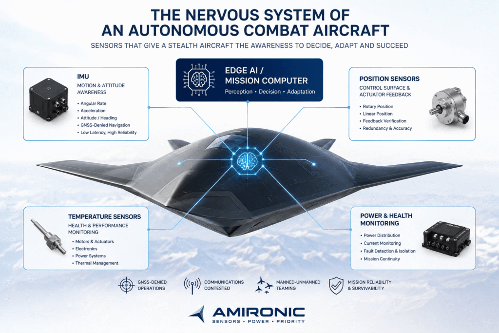
Figure 1 – The Nervous System of an Autonomous Combat Aircraft: AI can make decisions, but it depends on a continuous and reliable stream of data from the IMU, position and temperature sensors, and power monitoring systems. Together, they provide the mission computer with a real-time picture of the aircraft’s motion, mechanism positions, and overall system health.

When GPS Disappears: The IMU Becomes a Critical Part of the Aircraft’s State Awareness

An autonomous combat aircraft cannot begin a mission on the assumption that GPS will remain available and reliable throughout the entire flight.

In a modern operational environment, GNSS signals may be jammed, blocked or, even worse, deceived through spoofing.

The distinction is significant.

With jamming, the system can generally recognize that it has lost the GNSS signal.

With spoofing, it may continue receiving position data that appears valid – but is actually incorrect.

For an autonomous platform, this is a particularly serious problem. If the computer cannot fully trust its external positioning source, it needs additional sources of information that allow it to estimate its own state and detect inconsistencies between sensors.

One of the most important of these is the Inertial Measurement Unit – IMU.

The IMU Is the Aircraft’s “Sense of Balance”

An IMU continuously measures the motion of the platform using gyroscopes and accelerometers.

It does not need to ask a satellite what happened to the aircraft.

It measures motion directly onboard the aircraft itself.

Angular Rate and Acceleration data are used by navigation, stabilization and control systems to estimate how the aircraft is moving and how its state is changing.

In a real system, of course, the IMU does not operate alone. Its data can be combined with GNSS, cameras, radar, magnetometers, barometers and other sources through Sensor Fusion.

This is an important distinction: an IMU is not a “replacement for GPS.”

It is an independent inertial source of information that becomes particularly important when an external navigation source is unavailable or cannot be trusted.

The Longer the Mission – the More Small Errors Matter

An inertial system has a fundamental limitation: errors accumulate over time.

A small gyro bias, measurement noise, temperature variations and scale factor errors can gradually affect the state estimate.

That is why it is not enough to ask:

“Does the aircraft have an IMU?”

The engineering question is:

“What kind of IMU?”

For a tactical platform, parameters that should be considered include:

  • Bias Stability
  • Angle Random Walk
  • Scale Factor Error
  • Bandwidth
  • Data Rate
  • Latency
  • Noise
  • Temperature Compensation
  • Shock & Vibration Performance

Two IMUs may appear to provide the same six measurement channels on paper – three gyroscopes and three accelerometers – yet behave very differently when installed on a fast-moving, high-vibration, highly dynamic platform.

In Autonomous Systems, Latency Becomes Part of the Decision Loop

This introduces another interesting change.

Traditionally, it was natural to think of the IMU primarily as part of the navigation system or Flight Control system.

But when Edge AI begins making decisions onboard the platform itself, information about aircraft motion also becomes part of the input used for mission-level decisions.

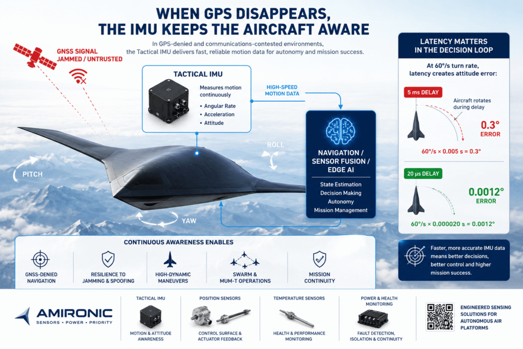
Suppose the aircraft is maneuvering at an angular rate of:

60°/sec

A system receives data describing the state of the platform with a delay of 5 milliseconds.

During that short period, the aircraft has already rotated:

60 × 0.005 = 0.3°

By comparison, with a delay of 20 microseconds:

60 × 0.000020 = 0.0012°

This does not mean that every system onboard the aircraft necessarily requires 20 µs latency.

But it illustrates an important principle:

The more dynamic the platform and the faster its control and decision loops, the more the age of the data matters.

The algorithm can be extremely fast.

The processor can be extremely powerful.

But if the data on which the decision is based describes the aircraft’s state several milliseconds ago, the computer is making a decision about a reality that has already changed.

Tactical-Grade IMU: Not Just Accuracy, but Real-World Performance

This is why platforms of this type may benefit from evaluating Tactical-Grade IMUs such as the IMU families offered by Gladiator Technologies.

For example, the LandMark™ 005 IMU can provide data rates of up to 10 kHz, bandwidth of up to 600 Hz, and Message Delay of less than 20 µs, together with inertial performance designed for dynamic tactical applications.

But these numbers are not the objective by themselves.

The objective is to provide the systems above the IMU with motion data that is accurate, stable and fast enough to support timely decisions.

And that brings us back to autonomy.

The AI decides what to do.
The Tactical IMU tells it what the aircraft is actually doing.

But knowing how the aircraft is moving is still not enough.

The computer can decide to execute a turn and send a command to a control surface.

Now an entirely different question arises:

How does it know that the control surface actually moved to the commanded position?

Figure 2 – When GNSS Cannot Be Trusted, Inertial Data Keeps Flowing: A Tactical IMU provides continuous motion data to the navigation, Sensor Fusion and Edge AI systems. On a dynamic platform, latency also matters: at a rotation rate of 60°/s, a 5 ms delay already represents an angular change of 0.3°, compared with just 0.0012° at a 20 µs delay.

The Aircraft Issued a Command. How Does It Know It Was Actually Executed?

Suppose the flight control computer decides to perform a maneuver.

It calculates the required response and sends a command to an actuator to move a control surface to a specific angle.

From the software’s perspective, the command has been issued.

But from the aircraft’s perspective, that still does not mean the action was actually performed.

The actuator may move precisely to the commanded position.

It may complete only part of the required travel.

It may respond more slowly than expected.

Mechanical play may develop.

And in the event of a failure, it may not move at all.

That is why, in a critical Flight Control system, it is not enough to know what was commanded.

The system also needs to know:

What actually happened?

Command Is Not Feedback

This is one of the fundamental principles of Closed-Loop Control.

The computer sends a command:

Commanded Position: 7.3°

A position sensor measures the actual mechanical position:

Actual Position: 7.2°

The control system can now compare the two values and adjust the command accordingly.

But if the sensor reports:

Actual Position: 3.1°

when the computer expects 7.3°, the system has learned something far more important:

The system is not behaving as commanded.

In an autonomous aircraft, that difference can turn an engineering parameter into operationally significant information.

This Is Where Position Sensors Come In

Different types of sensors can be used to measure motion in different mechanical systems.

Rotary Position Sensors measure angular movement and can be used in rotating mechanisms, shafts and systems where the actual angle needs to be known.

Linear Position Sensors measure linear movement and can provide feedback on the travel of an actuator or other linear mechanism.

In an aerospace application, the selection process involves much more than deciding whether a Rotary or Linear sensor is required.

Parameters such as Resolution, Accuracy, Linearity, Repeatability, Temperature Range, Vibration, Electrical Interface, Packaging – and, in some applications, Redundancy – must also be considered.

Variohm Group, for example, offers a range of technologies for rotary and linear position measurement, allowing the sensing principle to be matched to the mechanical and environmental requirements of the application.

From the aircraft architecture perspective, however, the specific sensing technology is only part of the story.

The objective is to close the loop:

Command → Actuator → Mechanical Movement → Position Measurement → Controller

And then again:

Measure → Compare → Correct

Thousands of times throughout the mission.

What Happens When Two Sensors Disagree?

In Flight-Critical systems, simply receiving a measurement may not be enough.

The system also needs to determine whether that measurement can be trusted.

Suppose two Position Feedback channels are installed on a critical mechanism.

Sensor A reports:

7.2°

Sensor B reports:

7.3°

The system has a reasonable indication that the measurements are consistent.

But suppose the readings suddenly become:

Sensor A:

7.2°

Sensor B:

11.8°

Now the situation is entirely different.

One of the sensors may be wrong.

There may be a wiring fault.

There may be a mechanical problem.

Or the source of the fault may lie somewhere else in the system.

Redundancy does not necessarily mean simply adding “another sensor in case the first one fails.”

It can allow the system to perform Cross-Checking, detect disagreement and initiate Fault Detection logic.

This becomes particularly important in an autonomous system.

There is no pilot to feel that the aircraft is behaving abnormally and then look at the instruments to determine what is happening.

The aircraft must be able to detect for itself that the command, the mechanical movement and the dynamic response are not consistent with one another.

This Is Where the IMU and Position Sensor Begin to Speak the Same Language

And this is where things become even more interesting.

Suppose the aircraft commands a control surface to move.

The position sensor reports:

The surface has reached the commanded angle.

At the same time, the IMU measures the aircraft’s dynamic response.

If the control surface appears to be in the correct position but the aircraft does not respond as the model expects, a different kind of discrepancy has emerged.

Each sensor sees a different part of reality.

The Position Sensor sees the mechanism.

The IMU sees the dynamic response of the platform.

When the control system combines information from different sources, it can build a richer picture than either sensor could provide on its own.

This is already a step beyond simple Position Feedback toward System-Level State Awareness.

But Another Warning Sign May Appear Before the Failure

Suppose the actuator is still reaching the commanded position.

The Position Sensor detects no problem.

The aircraft’s dynamic response also appears normal.

But the motor driving the mechanism is beginning to work harder.

Its temperature is gradually increasing.

Functionally, the system is still operating.

From a health perspective, however, a failure may already be developing.

And this brings us to the next layer of the aircraft’s sensing architecture:

Temperature Sensing.

Figure 3 – Command Is Not Confirmation: In a closed-loop flight control system, sending a command to an actuator is not enough. Rotary and linear position sensors measure the actual position and provide feedback to the controller, while the IMU measures the aircraft’s dynamic response. Comparing the command, actual position, and dynamic response enables more precise control, fault detection, and redundancy.

The System Is Still Working – But Is It Beginning to Fail?

One of the interesting challenges in an autonomous system is that failure is not always a binary event.

A component does not necessarily transition instantly from “healthy” to “failed.”

Sometimes, failure begins much earlier.

A bearing begins to generate more friction.

An actuator requires more current to perform the same movement.

A motor begins to run hotter.

Power Electronics operate at a higher temperature than usual.

An electrical connector develops increased resistance.

And throughout all of this, from the mission computer’s perspective:

The system is still working.

The command is sent.

The actuator reaches the required position.

The Position Sensor confirms it.

And the aircraft continues its mission.

But something has changed.

Temperature Is More Than an Environmental Parameter

When discussing a Temperature Sensor in an aerospace system, it is easy to think primarily about measuring ambient temperature.

But on an autonomous platform, temperature measurement can also help provide insight into the condition of the system itself.

Depending on the platform architecture, sensors may monitor areas such as:

  • Electric Motors
  • Actuators
  • Bearings
  • Power Electronics
  • Batteries
  • Power Distribution
  • Avionics
  • Gearboxes
  • Hydraulic Systems

The objective is not simply to know that a component is currently operating at, for example, 72°C.

A more interesting question may be:

Why did the temperature rise from 55°C to 72°C when the operating conditions barely changed?

This is where Temperature Monitoring begins to evolve from simple “Measurement” into Health Monitoring.

It Is Not Just the Temperature – It Is Also the Rate of Change

Suppose two identical actuators are operating under similar conditions.

Actuator A:

54°C → 56°C → 57°C

Actuator B:

54°C → 61°C → 69°C

Both may still be operating within their allowable temperature range.

But their behavior is clearly not the same.

An advanced Health Monitoring system can evaluate not only the absolute temperature, but also:

Rate of Change

Load

Duty Cycle

Ambient Temperature

Current Consumption

Historical Behavior

And this creates an important distinction from an autonomy perspective.

The aircraft is no longer asking only:

“Is the system working?”

It can begin asking:

“Is the system behaving the way a healthy system should behave?”

That is a significant difference.

From Temperature Sensing to Prognostics

As a system collects more data, that information can be used for Condition-Based Maintenance and potentially as part of Prognostics and Health Management – PHM.

This does not mean that a temperature sensor alone can predict a failure.

It cannot.

But it can provide another valuable indication when combined with other sources of information.

For example:

Position Sensor
Did the mechanism reach the commanded position?

Current Monitoring
How much current was required to get it there?

Temperature Sensor
How much heat was generated during operation?

IMU
Did the aircraft respond as expected?

When all of these parameters appear normal, confidence in the health of the system increases.

But suppose the mechanism still reaches the correct position while its current consumption and temperature gradually increase from one mission to the next.

The system now has information that the Position Sensor alone could never provide.

The mechanism may still be operational.

But a failure may already be developing.

On an Unmanned Aircraft, This Information Can Affect the Mission

This is where we move once again from engineering into operational decision-making.

Suppose an autonomous aircraft is at the beginning of a long-range mission.

One of its systems begins to show an abnormal Thermal Trend.

There is no Failure yet.

The system is still functioning.

But the Mission Management computer knows that the platform is hundreds of kilometers from its recovery point.

What should it do?

Continue the mission normally?

Reduce the load on the affected system?

Change the flight profile?

Transfer the function to a Redundant system?

Or determine that the risk of continuing the mission has become too high and return?

These are no longer questions about a temperature sensor.

They are questions of Autonomous Mission Management.

The sensor has simply provided the physical information on which a decision can be based.

And That Is Exactly the Role of Sensors in an Autonomous System

Variohm Group offers a range of temperature sensing technologies, including RTDs, Thermistors and application-specific Temperature Sensing solutions.

But here too, sensor selection should not begin with the question:

“Which Temperature Sensor is available in the catalog?”

It should begin with engineering questions:

What are we trying to measure?

What is the required temperature range?

What response time is required?

Where can the sensor be installed?

What is the thermal mass of the measurement point?

What Accuracy is required?

What level of resistance to Vibration, Shock and environmental conditions is required?

And most importantly:

What decision is the system expected to make from this information?

Because in an autonomous aircraft, a sensor is not valuable simply because of the number it measures.

It is valuable because of the decision that measurement can support.

Now Let’s Connect Everything: The Aircraft Needs to Know When It Is “Wounded”

So far, we have looked at different systems separately.

The IMU tells the aircraft how it is moving.

Position Sensors tell it whether mechanisms have executed their commands.

Temperature Sensors can indicate changes in the thermal condition of components and systems.

The power system can provide additional information about current, voltage and electrical faults.

But the truly interesting capability emerges when the aircraft begins to cross-check these different sources of information.

Because on the battlefield, the problem is not always a component that simply stops working.

Sometimes the aircraft is damaged.

Sometimes one system begins to degrade.

Sometimes a Sensor provides incorrect data.

And sometimes the only way to understand what has actually happened is to compare several independent sources of information.

This is where the next stage of autonomy begins:

Detect → Isolate → Reconfigure → Continue or Abort

Or, in simpler terms:

Can an autonomous combat aircraft know that it has been damaged – and determine whether it is still capable of fighting?

Figure 4 – A System Can Still Be Functional Without Being Healthy: Combining Position Feedback with current and temperature monitoring can reveal a degradation trend before it develops into a failure. This allows an autonomous system to reduce load, switch to a redundant system, modify the mission profile, or decide to return to base.

The Aircraft Has Been Hit. Who Decides Whether the Mission Continues?

So far, we have focused mainly on failures that develop within the aircraft’s systems.

But a combat aircraft does not operate in a laboratory.

It is sent into an environment where adversaries are trying to disrupt it, deceive it – and sometimes physically damage it.

Suppose an autonomous combat aircraft is operating deep inside hostile territory.

It is hit.

The aircraft is still flying.

There is no immediate loss of control, and there may not be a single Sensor declaring:

AIRCRAFT DAMAGED

Instead, there are indications.

The IMU detects an unexpected change in the aircraft’s dynamic behavior.

A position sensor in one of the systems reports movement that does not fully correspond to the command.

A temperature sensor in a particular area shows an abnormal increase.

The electrical system detects a change in current consumption or a fault on a specific branch.

Another sensor stops transmitting data altogether.

Each of these events, by itself, tells only part of the story.

The real challenge is to determine:

What happened to the aircraft?

Detect → Isolate → Reconfigure

In an advanced autonomous system, detecting a fault is only the first step.

Once the fault has been detected, the system must attempt to determine where it is and what it means.

This is the principle behind Fault Detection and Isolation – FDI.

Suppose, for example, that one position sensor begins returning data that is inconsistent with the rest of the system.

Is the mechanism actually in the wrong position?

Has the sensor itself failed?

Has the wiring been damaged?

Or is the measurement reflecting a real physical change in the aircraft?

This is where Redundancy and Sensor Fusion take on an additional role.

The system can compare:

Sensor A vs. Sensor B

Commanded State vs. Measured State

Position Feedback vs. IMU Response

Temperature Trend vs. Electrical Load

The aircraft’s mathematical model vs. its actual behavior

The more independent and reliable sources of information are available, the better the system can build an accurate picture of what is happening.

The objective is not necessarily to achieve absolute certainty.

On the battlefield, absolute certainty is not always possible.

The objective is to achieve sufficient confidence to make the next decision.

The Question Is Not Only “What Failed?”

The more important operational question is:

What is the aircraft still capable of doing?

That is a fundamental shift.

One system may have been damaged, while the platform remains capable of flight.

A particular capability may have been lost, while a Redundant system remains available.

The aircraft may still be capable of completing the mission – but only under a new set of limitations.

For example, the Mission Management system could theoretically determine:

Flight Capability: AVAILABLE

Navigation Confidence: DEGRADED

Thermal Condition: ACCEPTABLE

Mission Sensor: AVAILABLE

Communication: INTERMITTENT

In such a situation, the decision does not necessarily have to be:

FAILURE → RETURN HOME

Other options may exist:

Continue Mission

Continue with Restrictions

Change Flight Profile

Reduce Electrical / Thermal Load

Switch to Redundant Sensor

Reconfigure Navigation Sources

Transfer Task to Another Platform

Abort Mission

This goes far beyond conventional Built-In Test.

It becomes Mission-Aware Fault Management.

The Aircraft Must Understand Not Only the Failure – but Its Impact on the Mission

Suppose two autonomous aircraft experience exactly the same fault.

Aircraft A is 50 km from base after completing its mission.

Aircraft B is 800 km from base and still on its way to the target area.

From an engineering perspective, the fault is identical.

From an operational perspective, it is not the same fault.

The decision may depend on location, remaining fuel or energy, the threat environment, the condition of other onboard systems, the availability of other platforms, and the importance of the mission.

This is why, in the world of Autonomy, Health Monitoring and Mission Management begin to converge.

The sensors do not make the operational decision.

But without reliable information from them, the system making that decision has little solid ground to work from.

Redundancy: You Do Not Always Need Two of Everything

When discussing survivability, it is easy to imagine that every component in the aircraft simply needs to be duplicated.

In reality, Redundancy can be much more sophisticated.

There can be Hardware Redundancy – two or more sensors measuring the same parameter.

There can be Analytical Redundancy – comparing one measurement with information that can be inferred from other sensors or from the system model.

And there can be Functional Redundancy – another system that allows part of the mission to continue even after a particular capability has been lost.

For example, if one navigation source becomes unreliable, Sensor Fusion may assign greater weight to other sources.

If one Sensor disagrees with two independent sources, the system may reduce its confidence in that sensor.

If a temperature sensor indicates abnormal heating in a particular area while an electrical anomaly is detected at the same time, the combination of those measurements may strengthen the assessment that a real fault is developing.

This is an important distinction between:

More Sensors

and:

Better System Awareness

The objective is not to fill the aircraft with sensors.

The objective is to select the right measurements, in the right locations, and design an architecture capable of turning them into useful information.

What If the Aircraft Is Not Alone?

This brings us to the next stage.

A next-generation autonomous combat aircraft may operate as part of a team: alongside a manned aircraft, alongside other Collaborative Combat Aircraft, or as part of a distributed network of unmanned platforms.

In such a scenario, a failure on one platform is not necessarily a problem for that platform alone.

Suppose one aircraft loses part of its sensing capability.

Another aircraft in the formation may still have that capability.

Suppose one platform has to limit its maneuvers because of a newly detected system constraint.

Another platform may be able to take over part of its mission.

Now, the ability of each aircraft to understand its own state becomes the foundation for the entire group’s ability to operate collaboratively.

Before aircraft can share missions, they need to be able to share something even more fundamental:

State.

Where am I?

How am I moving?

Which systems can I trust?

What is my confidence level in the data?

And which capabilities are still available to me?

This is one of the reasons why the transition from Automation to Autonomy does not begin with AI alone.

It begins much deeper in the architecture:

Sensing → State Estimation → Health Assessment → Decision → Action

Only when this chain is sufficiently reliable can we seriously begin to talk about aircraft taking on more decision-making responsibility themselves.

The Next-Generation Stealth Aircraft Must Be Difficult to Detect – but Also Difficult to Surprise

Stealth is designed to reduce the enemy’s ability to determine where the aircraft is.

Autonomy demands almost the opposite internally:

The aircraft itself must know, with the highest practical level of confidence, what is happening inside it.

It needs to sense its own motion.

Know the state of its mechanisms.

Monitor the thermal condition of critical systems.

Detect electrical abnormalities.

Distinguish between a Sensor Fault and a real change in platform behavior.

And understand whether a particular failure has changed its ability to complete the mission.

We can call this:

Platform Self-Awareness.

Not in the sense of consciousness.

But in the engineering and operational sense:

The ability of the platform to build a reliable picture of its own state – and use that information to continue operating.

Figure 5 – Damage Does Not Necessarily Mean the End of the Mission: Combining data from the IMU, position and temperature sensors, and the electrical system can help detect anomalies, isolate the source of a fault, and assess which capabilities remain available. From there, an autonomous system can reconfigure itself and determine whether to continue the mission, modify it, or return to base.

The Autonomous Aircraft Will Not Necessarily Fly Alone

When we think about an unmanned combat aircraft, it is easy to imagine an independent platform heading out on a mission by itself.

But one of the major directions in the evolution of military aviation is actually the integration of multiple platforms.

A manned fighter may operate alongside several unmanned platforms – Collaborative Combat Aircraft (CCA) – each contributing different sensors, capabilities and mission functions.

One platform may carry a Sensor Payload.

Another may serve as a Communications Relay.

Another may carry Electronic Warfare systems.

And another may be assigned a different task as the operational situation evolves.

The objective is not necessarily to create a “robotic fighter” that completely replaces the manned combat aircraft.

Instead, the direction may be toward a distributed combat system, in which humans and autonomous platforms operate together.

But before such a team can function effectively, each platform first needs to know something fundamental:

What is my own state?

Before Sharing Targets, You Need to Share State

Suppose several unmanned aircraft are operating alongside a manned fighter.

One reports:

NAVIGATION: HIGH CONFIDENCE

FLIGHT SYSTEMS: NOMINAL

MISSION SENSOR: AVAILABLE

COMMUNICATION: DEGRADED

Another reports:

NAVIGATION: DEGRADED

FLIGHT SYSTEMS: NOMINAL

MISSION SENSOR: AVAILABLE

THERMAL STATUS: CAUTION

This information may be just as important as the location of the target.

If a Mission Management system wants to transfer a task from one platform to another, it needs to know not only which aircraft is closer, but also:

Which platform is capable of performing the mission?

Which one has the appropriate Sensor?

Which platform is in better system health?

Which one has sufficient fuel or energy remaining?

Which platform has the more reliable navigation solution?

And which aircraft may need to leave the formation and return?

In other words, collaborative Autonomy begins with the Self-State Awareness of every member of the team.

What Happens When Communications Are Not Perfect?

This is a critical issue.

A military system cannot assume that a fast, continuous and reliable data link will always exist between every platform.

The adversary may attempt to disrupt communications.

The distances involved may be significant.

Line-of-Sight conditions may change.

Bandwidth may be limited.

And some platforms may temporarily become disconnected from the network.

This is one of the reasons Edge AI becomes so important.

Instead of transmitting every image, every measurement and every decision to a centralized computer, part of the processing can take place onboard the platform itself.

The aircraft can process local information, build a State Estimate, detect anomalies and make certain decisions within the rules and authorities defined for it.

It does not necessarily need to transmit all of its Raw Data over the network.

Depending on the system architecture, it may instead share more relevant, processed information.

For example:

Position

Velocity

Heading

Navigation Confidence

Sensor Availability

System Health

Mission Capability

And once again, this brings us back to the sensors.

Edge AI Cannot Fix Bad Sensor Data

You can install an extremely powerful AI processor onboard the aircraft.

You can run advanced algorithms on it.

You can give it Computer Vision, Target Recognition and Mission Planning capabilities.

But there is a fundamental limitation:

The algorithm cannot know more than the information available to it allows it to know.

If motion data arrives late, it is working with an outdated State.

If Position Feedback is unreliable, it cannot know with confidence where the mechanism actually is.

If Thermal Monitoring is absent where it is needed, the computer cannot detect a trend that was never measured.

And if GNSS is disrupted and no additional sources of information were designed into the architecture to handle that condition, even an excellent algorithm may build an incorrect picture of reality.

That is why autonomous systems are still subject to a very simple principle:

Garbage In → Garbage Out

Or, in terms more appropriate for a combat aircraft:

Autonomy is only as good as the data feeding it.

Sensor Fusion Is Not a Sensor

The term Sensor Fusion appears in almost every discussion about autonomous systems.

But it is important to understand what it is not.

Sensor Fusion is not a magic sensor that fixes every problem.

It is a process that combines information from different sources to build a better estimate of the state of the system or its environment.

For example, a navigation system may combine information from:

GNSS

IMU

Radar / EO

Barometer

Magnetometer

Terrain or Visual References

When one source becomes less reliable, the system may adjust the weight assigned to it – provided that other sources are available and can be trusted.

The same principle can be applied to Health Monitoring.

The Position Sensor provides one piece of information.

The Temperature Sensor provides another.

The electrical system contributes additional data.

The IMU measures the resulting dynamic response.

The real value emerges when the system can cross-check the information.

This is why good Sensor Fusion begins long before the algorithm.

It begins with sensor selection.

Not Every Sensor Needs to Be “the Most Accurate”

This is an especially important point for system engineers.

It is easy to define a requirement:

Give me the most accurate sensor available.

But on an airborne platform, Accuracy is only one variable.

Other parameters may be equally important:

Latency

Bandwidth

Repeatability

Temperature Stability

Shock & Vibration

Size

Weight

Power Consumption

Electrical Interface

Redundancy

Reliability

Environmental Sealing

And, of course:

Cost

A sensor with excellent Accuracy but Latency that does not match the requirements of the control loop may be the wrong choice.

A highly accurate sensor that cannot maintain its performance across the mission temperature range may also become problematic.

And a sensor that is nearly perfect from a metrology perspective but is too large or too heavy may simply be unsuitable for an airborne platform.

Sensor selection for an autonomous platform is therefore a Systems Engineering Trade-Off.

The right question is not:

“What is the best sensor?”

It is:

“What does the system need to measure, at what quality and speed, and under what conditions, in order to make the right decision?”

SWaP-C: When Millimeters and Watts Begin to Affect the Mission

On an unmanned stealth combat aircraft, this question becomes even more significant.

Every component occupies space.

Every component adds weight.

Every component consumes power.

And every watt consumed onboard ultimately becomes heat that must also be managed.

This is why engineers use the term:

SWaP-C – Size, Weight, Power and Cost

But on a stealth platform, SWaP-C is more than an engineering convenience.

It can affect range.

Endurance.

Payload.

Thermal Management.

Reliability.

And the ability to integrate more functionality into a limited volume.

In other words, even the selection of a small sensor can ultimately become part of a much larger operational equation.

And this brings us to an interesting paradox:

The more autonomous the aircraft becomes, the more information it needs.

More information requires more Sensing, Processing and Communication.

Yet the aircraft still needs to remain compact, lightweight and efficient – and, in the case of a stealth platform, maintain a low signature.

The next-generation challenge is not simply to give the aircraft more senses.

It is to give it the right senses – without allowing the nervous system itself to become a burden.

Figure 6 – Autonomy Does Not Mean Operating Alone: In a Manned-Unmanned Teaming environment, each CCA/UCAV needs to understand its own state – position, navigation confidence, system health, and mission capability – before it can effectively share information and tasks with other platforms. Even when communications are degraded, Edge Autonomy can allow the platform to continue operating within its defined mission parameters.

Engineering Autonomy from the Sensor Up

After discussing AI, Sensor Fusion, CCA and Mission Management, it is easy to assume that the primary challenge of an autonomous combat aircraft lies in software.

But ultimately, all of this digital architecture is connected to a physical world.

An aircraft rotates.

A wing flexes under load.

A mechanism changes position.

A motor heats up.

Current increases.

Temperature changes.

A system is exposed to Vibration and Shock.

And the computer cannot “know” any of these things unless there is a way to measure them.

That is why the design of an autonomous system should begin with a fundamental question:

What does the aircraft need to know?

And only then:

How are we going to measure it?

Four Layers of Awareness

We can think of the platform’s “nervous system” in terms of four families of information.

1. Motion Awareness – What Is the Aircraft Itself Doing?

This is where the IMU and inertial navigation systems come into play.

They provide Angular Rate and Acceleration data and form part of Attitude / State Estimation, Flight Control and Navigation processes.

In an environment where GNSS may be Jammed or Spoofed, the quality of inertial information becomes even more important.

In highly dynamic applications, parameters such as:

Bias Stability

Angle Random Walk

Bandwidth

Data Rate

Message Latency

Temperature Performance

can all affect the quality of the information delivered to the systems above the IMU.

This is the type of environment for which Tactical-Grade IMUs, such as the IMU families from Gladiator Technologies, are designed.

2. Position Awareness – Where Are the Mechanisms Actually Positioned?

The computer knows what it commanded.

The position sensor tells it what actually happened in the mechanical world.

Depending on the mechanism, Rotary Position Sensors can be used to measure angular position, while Linear Position Sensors can measure linear travel.

The applications are not limited to a single type of mechanism.

Position Feedback may be relevant to Flight Control systems, opening and closing mechanisms, Steering, Servo Mechanisms, Antenna Positioning, Payload Mechanisms and other mechanical systems where the actual position needs to be known.

Variohm Group offers a range of technologies for rotary and linear position measurement, including Contacting and Contactless solutions that can be selected according to the requirements of the application.

On an airborne platform, the question is not simply:

Rotary or Linear?

It also includes:

What is the required range of motion?

What Accuracy is required?

What Repeatability is required?

What happens across the operating temperature range?

What level of Shock and Vibration resistance is required?

Is Redundancy required?

And what happens if the sensor itself fails?

3. Thermal Awareness – Where Is Stress Beginning to Develop?

Temperature can provide information about the environment, but also about the condition of the system itself.

RTDs, Thermistors and other Temperature Sensing technologies can be integrated into the monitoring of:

Electric Motors

Bearings

Power Electronics

Avionics

Batteries

Gearboxes

Mechanical Assemblies

and other systems where thermal changes may be significant.

Here too, Variohm Group offers a range of temperature sensors and application-specific sensing solutions.

But as we have seen, the real value is not always the instantaneous temperature.

Sometimes the Trend matters more.

A component operating at 70°C today is not necessarily less healthy than one operating at 55°C.

The relevant questions are what the component was designed for, what load it is operating under – and whether its behavior is changing over time.

4. Electrical Awareness – What Is Happening in the Power System?

The aircraft’s nervous system cannot ignore the electrical system that keeps it alive.

An autonomous aircraft may contain Mission Computers, communications systems, EW, Sensors, Navigation, Processing and Payloads – and every one of them depends on reliable electrical power.

A fault on one branch should not necessarily bring down the entire system.

That is why Circuit Protection, Power Distribution, Current Monitoring and Fault Isolation are also part of the platform’s survivability architecture.

From an autonomy perspective, electrical information can itself become State Data.

Not simply:

Breaker Tripped

but:

Which capability did I lose as a result?

Can the affected branch be isolated?

Is an alternative power source available?

Can the mission continue with a reduced electrical load?

This is where the power system connects back to Mission Management.

The Right Sensor Does Not Begin with a Part Number

This may be one of the most important points for an engineer at the beginning of a design.

When a customer says:

“I need a Position Sensor.”

that is not yet a complete engineering requirement.

The same applies to an IMU or a Temperature Sensor.

Selecting a component requires understanding the application.

For a Position Sensor, for example, we would want to know:

What exactly is moving?

Rotary or Linear?

What is the required Travel or Angle?

What is the speed of movement?

What Accuracy and Resolution are required?

What Output is required?

What is the supply voltage?

What is the operating temperature range?

What are the Shock and Vibration requirements?

What are the dimensional and installation constraints?

Is Redundancy required?

What operating life is required?

For an IMU, the questions are different:

What Bias performance is required?

What are the platform dynamics?

What Angular Rate Range is required?

What Bandwidth is needed?

What Data Rate?

What is the allowable Latency?

What is the operating temperature range?

What Interface is required?

What are the SWaP requirements?

And for a Temperature Sensor:

What are we measuring?

Where are we measuring it?

What temperature range?

What Accuracy?

What Response Time?

What Probe or Housing?

How will it be installed?

And what is the mechanical environment?

Only after these questions have been answered should the search for a part number begin.

Because in an Autonomous Aircraft, One Spec Almost Never Tells the Whole Story

An IMU is not “good” simply because it has low Bias.

A Position Sensor is not “good” simply because it offers high Accuracy.

A Temperature Sensor is not “good” simply because it can measure up to 200°C.

Each one operates as part of a larger system.

The real question is how its data will affect:

Control Loop

State Estimation

Fault Detection

Sensor Fusion

Health Monitoring

Mission Management

This is where component selection stops being simply Purchasing and becomes Systems Engineering.

The Next-Generation Aircraft Will Need More Than AI

The headlines about next-generation combat aircraft will most likely focus on AI.

Stealth.

Swarming.

CCA.

The ability to fly without a pilot.

And weapons.

But beneath all of these is a much less glamorous – yet equally critical – layer.

The layer that measures reality.

For an aircraft to make a decision, it first needs information.

To detect a fault, something has to measure the anomaly.

To compensate for a failure, the system first needs to know that the failure occurred.

And to continue operating when GPS, communications or another system is unavailable, the architecture needs additional sources of information that it was designed to rely on.

The entire article can therefore be summarized in one idea:

The AI decides.
The sensors make sure it has something real to decide with.

Or, put another way:

Autonomy makes the decision. The sensing system makes sure that decision is grounded in reality.

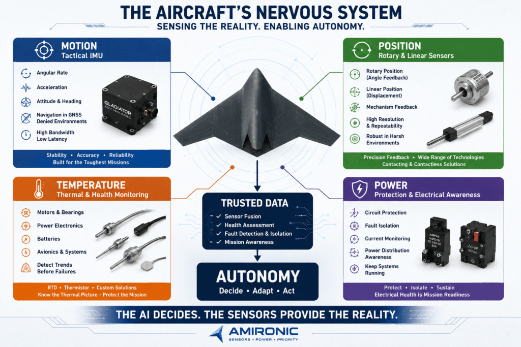
Figure 7 – The Nervous System of an Autonomous Aircraft: Motion data from the IMU, position feedback from rotary and linear sensors, thermal condition data, and electrical system protection and monitoring work together to build a reliable picture of the platform’s state. The AI makes the decision – but the sensors provide the reality on which that decision is based.
Conclusion: Autonomy Begins Long Before AI

The next generation of autonomous combat aircraft will not simply be fighter aircraft with the pilot removed.

Removing the human from the cockpit changes the requirements of the entire platform.

The aircraft needs to know how it is moving even when GNSS cannot be trusted. It needs to know whether its mechanisms are actually where they are supposed to be, detect thermal or electrical changes before they develop into failures, distinguish between a Sensor Fault and a real physical event – and assess which capabilities remain available when something goes wrong.

And as more decision-making moves to the Edge, the demand for reliable, fast and continuous information only increases.

This is why Autonomy is not just a software problem.

Beneath the AI, Sensor Fusion and Mission Computer lies a physical layer of sensors and protection systems that connects the algorithm to the real world.

A Tactical IMU provides information about the motion of the platform.

Rotary and Linear Position Sensors provide Feedback on the actual position of mechanisms.

Temperature Sensors help build a picture of the thermal condition of the platform and identify abnormal trends.

And Circuit Protection and Power Monitoring help protect critical systems, isolate faults and maintain functional continuity wherever possible.

Each measures something different.

Together, they help the aircraft answer the most important question:

What is actually happening to me right now?

Only when that question can be answered reliably can the system move on to the next one:

What should I do about it?

Designing the Sensing Architecture for Your Next Platform?

At Amironic, we work with engineers from the requirements-definition stage – from selecting Tactical IMUs from Gladiator Technologies, through Rotary and Linear Position Sensors and Temperature Sensors from Variohm Group, to Circuit Protection and electrical protection solutions for critical systems.

The objective is not to begin with a part number.

The objective is to understand what the system needs to know, at what level of performance and under what environmental conditions – and then select the appropriate sensing technology.

Because in an autonomous aircraft:

The AI decides.
The sensors provide the reality.

Frequently Asked Questions – FAQ

What is the difference between an automated aircraft and an autonomous aircraft?

An automated system typically performs predefined actions, routes or rules. An autonomous system can use information from its sensors and environment to adapt its behavior to changing conditions, within the objectives, permissions and constraints defined for it.

What is a UCAV?

UCAV – Unmanned Combat Aerial Vehicle is an unmanned aircraft designed for combat missions. Unlike UAVs used primarily for surveillance or intelligence gathering, a UCAV may participate in strike missions, electronic warfare, intelligence operations, support for other platforms and other operational roles.

What is a Collaborative Combat Aircraft – CCA?

CCA – Collaborative Combat Aircraft refers to unmanned combat aircraft designed to operate collaboratively with manned aircraft and other platforms. They may carry Sensors, EW, Communications, Weapons or other Payloads and perform missions as part of a distributed combat architecture.

Why does an autonomous aircraft need an IMU if it has GPS?

GPS/GNSS provides an excellent external navigation source when it is available and reliable. In a military environment, however, it may be disrupted by Jamming or deceived through Spoofing.

An IMU – Inertial Measurement Unit locally measures the platform’s accelerations and angular rates and does not depend on receiving a satellite signal. In a practical navigation architecture, IMU data is typically combined with GNSS and other sources through Sensor Fusion.

Can an IMU allow an aircraft to fly without GPS?

An IMU is an important component for navigation in a GNSS-Denied environment, but it is not a magic replacement for GPS over an unlimited period of time.

Inertial errors accumulate over time. Advanced navigation systems may therefore combine IMU data with additional sources such as Radar, EO/Visual Navigation, Barometers, Magnetometers, Terrain Referencing or other navigation aids.

In general, better IMU performance can help maintain a higher-quality State Estimate between updates from external sources.

Which parameters are important when selecting a Tactical IMU for a UAV or UCAV?

The answer depends on the application, but important parameters may include Bias Stability, Angle Random Walk, Scale Factor, Angular Rate Range, Bandwidth, Data Rate, Latency, Noise, Temperature Performance, Shock & Vibration, Interface, and Size, Weight and Power – SWaP.

There is therefore no single IMU that is “best” for every platform.

Why is IMU latency important in an autonomous system?

Latency determines how closely the information reaching the control or processing system represents the platform’s state now, rather than its state several milliseconds earlier.

For example, at a rotation rate of 60°/s, a 5 ms delay corresponds to an angular change of 0.3°. In highly dynamic systems with fast control loops, the age of the data can therefore become an important design parameter.

Why are position sensors needed in an autonomous aircraft?

A computer can command a mechanism to move, but issuing the command does not prove that the movement actually occurred.

Rotary Position Sensors and Linear Position Sensors measure the actual position and provide Closed-Loop Feedback. This allows the system to compare Commanded Position with Actual Position, make corrections and detect anomalies or faults.

What is the difference between a Rotary Position Sensor and a Linear Position Sensor?

A Rotary Position Sensor measures angular position or rotational movement.

A Linear Position Sensor measures position or travel along a linear axis.

The choice depends on the mechanics of the system, travel range, accuracy, speed, environmental conditions, electrical interface, and Reliability and Redundancy requirements.

Why are temperature sensors needed in an autonomous aircraft?

Temperature Sensors can be used not only to measure environmental conditions, but also for Health Monitoring of systems and components such as electric motors, Bearings, Power Electronics, Batteries, Avionics and mechanical assemblies.

In some cases, a change in the temperature trend – rather than the absolute temperature alone – can provide an early indication that system behavior is changing.

What is Sensor Fusion?

Sensor Fusion is the process of combining information from multiple sources to create a more reliable estimate of the state of the platform or its environment.

For example, a navigation system may combine GNSS, IMU and additional sensing sources. A Health Monitoring system may compare Position, Temperature, Electrical Data and the dynamic response of the platform.

Sensor Fusion does not replace high-quality sensors – it depends on the quality and reliability of the information being fed into it.

What is Platform Self-Awareness in an autonomous aircraft?

This does not mean “self-awareness” in the human sense.

In an engineering context, Platform Self-Awareness is the ability of the system to build a picture of its own condition: how it is moving, the health of its systems, which data can be trusted, whether a fault exists, and which capabilities remain available.

This information can support Flight Control, Fault Management and Autonomous Mission Management.

Can an autonomous aircraft continue its mission after a failure?

In principle, an appropriately designed architecture can support Fault Detection, Isolation and Reconfiguration.

Instead of treating every failure as an immediate reason to terminate the mission, the system may assess which capabilities have been lost, which redundant systems remain available, and the risk associated with continued operation.

The actual capability depends on the platform architecture, Redundancy, the type of failure and the mission rules defined for the system.

How do you begin selecting sensors for an autonomous airborne platform?

Do not begin with a part number.

Begin by defining what the system needs to know and what it is expected to do with that information.

Then define the required Accuracy, Range, Bandwidth, Latency, Temperature, Shock & Vibration, Interface, SWaP, Reliability and Redundancy for the application.

Only once those requirements are understood should the appropriate IMU, position sensor, temperature sensor or electrical protection solution be selected.


Key Terms to Know

UAV – Unmanned Aerial Vehicle
An unmanned aircraft. A broad term covering platforms used for surveillance, intelligence, communications, logistics, combat and other missions.

UCAV – Unmanned Combat Aerial Vehicle
An unmanned combat aircraft designed to perform military missions as part of a combat system.

CCA – Collaborative Combat Aircraft
An unmanned combat aircraft designed to operate collaboratively with manned aircraft and other unmanned platforms.

MUM-T – Manned-Unmanned Teaming
Operational collaboration between manned and unmanned platforms.

Automation
Automatic execution of predefined actions or sequences of actions.

Autonomy
The ability of a system to use information from its sensors and environment to adapt its behavior to changing conditions within defined objectives, rules and permissions.

Edge AI
Running AI algorithms directly onboard the platform rather than depending entirely on remote processing or a continuous communications link.

IMU – Inertial Measurement Unit
An inertial measurement unit that typically uses gyroscopes and accelerometers to measure Angular Rate and Acceleration.

Tactical-Grade IMU
An IMU performance class intended for tactical applications requiring higher levels of accuracy, stability and dynamic performance than basic commercial MEMS solutions.

Bias Stability
A measure of how stable a sensor’s Bias remains over time. It is an important parameter in inertial sensor performance.

ARW – Angle Random Walk
A measure associated with gyroscope noise and its contribution to angular error accumulation over time.

Bandwidth
The range of frequencies over which a sensor can usefully respond to dynamic changes.

Data Rate
The rate at which a sensor provides samples or data messages to the system.

Latency / Message Delay
The time between a measurement or generation of information and the point at which that information becomes available to the system using it.

GNSS – Global Navigation Satellite System
A general term for satellite navigation systems such as GPS, Galileo and GLONASS.

GNSS-Denied Environment
An environment in which GNSS cannot be relied upon for navigation due to blockage, interference, signal availability or other factors.

Jamming
Radio-frequency interference intended to disrupt or prevent a receiver from obtaining the legitimate signal.

Spoofing
Transmission of deceptive signals intended to cause a system to accept false information as if it were legitimate navigation data.

Sensor Fusion
The combination of information from multiple sensors or data sources to produce a more reliable State Estimate.

State Estimation
Estimating the state of the platform – such as position, velocity, Orientation and dynamic condition – using measurements and models.

Rotary Position Sensor
A sensor used to measure angular or rotational position.

Linear Position Sensor
A sensor used to measure linear position or travel.

Position Feedback
Measurement of the actual position and return of that information to the control system for comparison with the commanded state.

Closed-Loop Control
A control architecture in which the measured result is fed back to the controller, allowing it to correct the command based on the difference between the desired and actual states.

Redundancy
The use of alternative sources, components or functions to improve Reliability, enable Cross-Checking or maintain operation following a failure.

FDI – Fault Detection and Isolation
The process of detecting that a fault exists and attempting to isolate the affected component, sensor or subsystem.

PHM – Prognostics and Health Management
The use of condition data, trends and models to assess system health and identify degradation or potential failure.

Health Monitoring
Monitoring the condition of components and systems using information such as Temperature, Current, Position, Vibration and other parameters.

Platform Self-Awareness
In an engineering context, the ability of a platform to build a reliable picture of its own motion, system health and remaining capabilities.

Mission-Aware Fault Management
Fault management that considers not only what has failed, but also how the failure affects the platform’s ability to continue the mission.

SWaP-C – Size, Weight, Power and Cost
Four major design considerations: size, weight, power consumption and cost. On airborne platforms, they can directly affect Payload, Endurance, Thermal Management and overall system architecture.

Mission Computer
A computer that processes and manages mission-related functions and integrates information from multiple systems onboard the platform.

BIT – Built-In Test
Built-in diagnostic and test capabilities used to detect faults and monitor system condition.

Reconfiguration
Changing how the system uses its resources, sensors or subsystems in response to a failure or change in mission conditions.

Mission Continuity
The ability to preserve some or all operational capability following a failure, loss of communications or degradation of a particular system.

Tags: Amironic

Related Articles

From 5kW to 100kW Racks – The Engineering Challenges Behind Modern AI Data Centers

27/05/2026amironicLTD

Why Systems Reset Even When Voltage Stays “Within Range”

23/02/2026amironicLTD

Tungsten-Based Materials in Advanced Inspection and Measurement Systems

05/02/2026amironicLTD

Recent Posts

  • Fighter Aircraft Without a Pilot: How Do You Build a Nervous System for an Aircraft That Must Make Its Own Decisions?
  • Why a Standard Pressure Sensor Isn’t Always Suitable for Hydrogen Systems
  • Hands on the Keyboard, Foot on the Radio – Why Push-to-Talk Is Moving to the Floor in Control Rooms
  • Why Every Battery Pack Needs a Temperature Sensor – Not Just Electric Vehicles
  • Why a Dirty Lens Is More Than Just an Optical Problem – It’s an Engineering Challenge in Endoscopy Systems

Categories

  • Air Switch
  • Circuit Breakers
  • Elapsed Time Indicator
  • Feedthrough
  • Footswitches
  • Gears & Transmission
  • Hour Meters
  • Infra Red Switches
  • INFRARED LAMPS
  • Low Noise Inertial MEMS
  • Mechanics
  • MEMS Gyroscope
  • MEMS Inertial
  • Microelectronics
  • Motors
  • Position Sensors
  • Power Supply
  • Pressure Sensors
  • Pressure Switch
  • Temperature Sensors
  • Tungsten and Molybdenum
  • Uncategorized
  • Vacuum Switches

Quick Contact

Fill out the form and our representatives will return to you

    Name (required)

    Email (required)

    Phone

    Message

    This site is protected by reCAPTCHA and the Google
    Privacy Policy and
    Terms of Service apply.

    Amironic Ltd.

    3 Rabinovich Street, Petah Tikva 4928144 , Israel. Tel: +972-3-9047744 E-mail: office@amironic.co.il
    Email
    Facebook
    Twitter
    LinkedIn
    YouTube
    Press on the ISO Certificate below for download
    ISO 9001:2015 Certification
    • MEMS Inertial
    • Circuit Breakers
    • Footswitches
    • Mechanical & Transmisions
    • Sensors
    • Motors
    • Electronics
    • Hand Control
    • Power Solutions

    News

    • Fighter Aircraft Without a Pilot: How Do You Build a Nervous System for an Aircraft That Must Make Its Own Decisions?
    • Why a Standard Pressure Sensor Isn’t Always Suitable for Hydrogen Systems
    • Hands on the Keyboard, Foot on the Radio – Why Push-to-Talk Is Moving to the Floor in Control Rooms
    • Why Every Battery Pack Needs a Temperature Sensor – Not Just Electric Vehicles
    • Why a Dirty Lens Is More Than Just an Optical Problem – It’s an Engineering Challenge in Endoscopy Systems
    About AmironicContactעברית
    © 2022 Amironic All rights reserved. All Trademarks are the property of their respective owners.
    • Increase Font
    • Decrease Font
    • Black & White
    • Inverse Colors
    • Highlight Links
    • Regular Font
    • Reset