flagעברית
flagEnglish
3 Rabinovich St., Petah-Tikva, Israel
+972 3 9047744
office@amironic.co.il
Facebook
Twitter
LinkedIn
YouTube
  • Products
    • MEMS Inertial
      • Gyros & Accels
      • IMU
      • Inertial Navigation
      • AHRS
    • Circuit Breakers
      • Airpax Circuit Breakers
      • Electronic Circuit Breakers
      • Aircraft Circuit Breakers
      • Thermal Circuit Breakers
      • Sealing Solutions & Guards
    • Footswitches
      • Pedals & Bellows
      • USB
      • Air Switches
      • Medical
      • Modular Bases System
      • Industrial
      • Foot Potentiometers
      • Wireless
    • Mechanical & Transmisions
      • Gears
      • Sealing Solutions
      • Gearboxes
      • Couplings
      • Shafts & Bearings
      • Fasteners
      • Mechanical & Springs
      • Linear Motion
      • Anti-Vibration
    • Sensors
      • Thermostats
      • Temperature
      • Position
      • Pressure
      • Speed
      • Level Sensor
      • Load Cells
      • Flex Sensors
      • Membrane Potentiometer
    • Motors
      • Geared DC
      • Brushless DC
      • Step Motors with Gearbox
      • Torque Motors & Brushless Servo
      • DC Motors
    • Electronics
      • Xenon & IR Lamps
      • Counters & Meters
      • Microelectronics Packaging
      • Waterproof Switches
      • Micro Switches
    • Hand Control
      • Operator Controls (JOYSTICK)
      • Electrical
      • Pneumatic (Medical)
      • USB Hand Control
      • Air Push Button
      • Pressure Switch
      • IR Switch
    • Power Solutions
      • Rugged & Military Power Supply
      • Input Power Protection
      • Sealed Military Power Adaptor
      • Triple Output Military Power Supply Series – up to 250 W
    • Materials
      • Molybdenum and Advanced Alloys (TZM, MOLA, HCT)
      • Tungsten (Wolfram) and Advanced Alloys – High-Performance Materials for Extreme Conditions
      • Materials for Gears
  • Shop
  • Companies
  • About Amironic
  • News
  • Contact
Product was added to your cart

Cart

waze

How to Identify an Existing Gear Without a Drawing – A Practical Measurement Guide for Engineers

Mechanics10/09/2026amironicLTD

You have a gear in your hand. Perhaps it is worn, perhaps one of its teeth has broken, or perhaps it is part of an older machine for which the original drawings are no longer available – and now you need to manufacture or order a replacement gear.

The natural response is to grab a caliper, count the number of teeth, and measure the outside diameter.

That is a good start.

But it still does not tell us with certainty exactly which gear we have.

Two gears can have the same number of teeth and even look almost identical, yet differ in Module, Pressure Angle, Profile Shift, Face Width, Bore, Material, Heat Treatment, or Accuracy Grade.

That is why reverse engineering a gear involves much more than simply saying, “24 teeth and a 52 mm diameter.”

In this guide, we will go step by step through the process of identifying an existing gear: what can be measured using simple tools, what can be calculated from those measurements, which parameters require further inspection – and when it is no longer a good idea to guess.


Before You Start: What Type of Gear Do You Have?

The first step is not measurement, but identifying the basic type of gear.

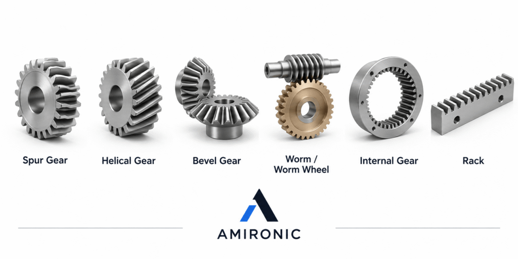
Gears come in a variety of geometries:

  • Spur Gear
  • Helical Gear
  • Bevel Gear
  • Worm / Worm Wheel
  • Internal Gear
  • Rack

Each type has its own geometry and measurement requirements.

This guide focuses primarily on Spur Gears, because a significant part of the identification process can be carried out using basic measurements and relatively simple calculations.

For Helical, Bevel, or Worm Gears, the identification process may require additional parameters and more specialized measurement tools.
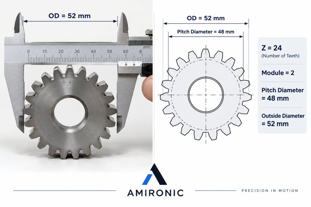
Step 1 – Count the Number of Teeth

Start with the simplest parameter:

Z – Number of Teeth

It is a good idea to mark one tooth with a marker and start counting from there, especially on gears with a large number of teeth.

Let’s assume we have:

Z = 24

Can we now search for “Spur Gear 24 Teeth” and place an order?

Definitely not.

The Number of Teeth Is Not a Part Number

A 24-tooth gear could be Module 1, Module 1.5, Module 2, or an entirely different Module.

It could also have a different Pressure Angle, Bore, Face Width, Material, or Accuracy Grade.

Therefore, the number of teeth is only the starting point.

We discuss this exact issue in more detail in the following article:

“I Have a 24-Tooth Gear. Send Me the Same One.”

Step 2 – Measure the Outside Diameter

The next measurement is:

OD – Outside Diameter

This is the diameter measured from the tips of the teeth on one side of the gear to the tips of the teeth on the opposite side.

For a small or medium-sized Spur Gear, this measurement can usually be taken with a caliper.

For example:

Number of Teeth = 24

Outside Diameter ≈ 52 mm

Now we can start calculating.

For a standard Spur Gear without significant Profile Shift, the following approximation applies:

OD = m × (Z + 2)

Where:

m = Module

Z = Number of Teeth

We can therefore rearrange the formula:

m ≈ OD / (Z + 2)

In our example:

m ≈ 52 / (24 + 2)

m ≈ 2

This gives us a good indication that we may be looking at a Module 2 gear.

But it is very important to pay attention to the word:

Indication.

We have not yet proven that it is Module 2.


Step 3 – Check Whether the Calculated Module Makes Sense

Module is one of the key parameters that defines tooth size.

The larger the Module, the larger the gear teeth.

In the Metric system, common standard Modules include:

0.5, 0.8, 1, 1.25, 1.5, 2, 2.5, 3, 4, 5, and others.

If our calculation gives us:

m = 1.99

It is very reasonable to investigate whether the gear is Module 2.

But if we get:

m = 1.73

we should not simply select the nearest standard value.

Possible explanations include:

  • Measurement error
  • Worn teeth
  • Profile Shift
  • A non-standard gear
  • A gear based on Diametral Pitch rather than Module
  • Special tooth geometry

Do Not Round the Number Just to Make It Fit a Catalog

This is one of the more dangerous mistakes in gear Reverse Engineering.

If the numbers do not line up, there is usually a reason.


Step 4 – Calculate the Pitch Diameter

Once we have an estimated Module, we can calculate the:

Pitch Diameter

For a standard Spur Gear:

d = m × Z

In our example:

m = 2

Z = 24

Therefore:

d = 2 × 24 = 48 mm

The Pitch Diameter is not a physical diameter that can simply be measured by placing a caliper across the gear.

It is an important theoretical geometric diameter on which the relationship between mating gears is based.

At this point, we apparently have a gear with:

  • 24 teeth
  • Module 2
  • An Outside Diameter of approximately 52 mm
  • A Pitch Diameter of 48 mm

We now know considerably more than we did at the beginning of the process.

But we still do not know enough to confidently manufacture a replacement gear.

Step 5 – If You Have the Mating Gear, Use It

One of the most important principles in Reverse Engineering is not to examine the gear in isolation.

If you also have access to the mating gear, it can provide valuable information and help verify whether the assumptions we have made so far are actually correct.

Let’s assume our first gear has:

Z₁ = 24

and our initial conclusion is:

Module = 2

Its Pitch Diameter is therefore:

d₁ = 2 × 24 = 48 mm

Now let’s assume the second gear in the system has:

Z₂ = 36

If both gears are Module 2, the Pitch Diameter of the second gear will be:

d₂ = 2 × 36 = 72 mm

For a standard pair of external Spur Gears, without Profile Shift that changes the Center Distance, the theoretical Center Distance can be calculated as:

a = (d₁ + d₂) / 2

Therefore:

a = (48 + 72) / 2 = 60 mm

We can now compare this result with the actual system.

If the existing Center Distance in the machine is approximately 60 mm, this provides strong additional evidence that our Module 2 assumption is reasonable.

If we measure a significantly different Center Distance in the machine, we should not ignore it.

Possible explanations include:

  • Profile Shift
  • A different Module than the one we estimated
  • An error in the OD measurement
  • Significant wear
  • A non-standard gear
  • Another geometry that we have not yet considered

In Reverse Engineering, consistency between several independent measurements is far more valuable than a single number that simply appears to be correct.


Step 6 – Pressure Angle: The Same Module Still Does Not Guarantee Compatibility

Let’s assume we have identified:

  • 24 teeth
  • Module 2
  • An OD of approximately 52 mm
  • A Pitch Diameter of 48 mm

Can we order a new gear now?

Not yet.

Another important parameter is:

Pressure Angle

The Pressure Angle is part of the tooth profile geometry and affects how force is transmitted between mating gears.

One of the most common Pressure Angles used in modern gears is:

20°

However, gears with:

14.5°

also exist, as do other geometries for certain applications.

Why Does It Matter?

Two gears can have:

The same Module

and

The same Number of Teeth

and still not be compatible if their Pressure Angles are different.

In other words:

Module 2, 24 Teeth is still not a complete gear specification.


Can You Measure the Pressure Angle with a Caliper?

Not reliably from the Outside Diameter alone.

This is an important point because, during Reverse Engineering, it is easy to become overly confident once the Number of Teeth and OD appear to match a standard Module.

But a caliper does not directly tell us the Involute Profile of the tooth.

For more accurate identification, depending on the gear and the required level of precision, methods such as the following can be used:

  • Gear Tooth Vernier
  • Span Measurement
  • Measurement Over Pins / Wires
  • Optical Measurement
  • CMM – Coordinate Measuring Machine
  • Gear Measuring Machine

In some cases, several measurements can be taken and compared with the theoretical geometry expected for a particular Pressure Angle.

For a simple, standard system, this may be sufficient.

For a precision or critical system, however, it is better not to rely on assumptions alone.


Step 7 – Now Measure the Gear Body

So far, we have focused mainly on tooth geometry.

But a gear is more than just its teeth.

It must fit onto the shaft, fit within the assembly, sit in the correct position, and transmit torque into the system.

That means we also need to document the complete geometry of the gear body.

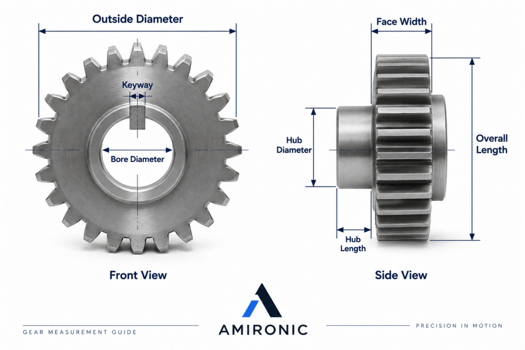
Face Width

Face Width is the width of the toothed portion of the gear.

It affects load-carrying capacity and the potential contact area between the mating gears.

Measure the width across the toothed section rather than assuming that the overall length of the part is also the Face Width.

Bore Diameter

Measure the diameter of the bore:

Bore Diameter

For example:

Ø15 mm

It is a good idea to measure the bore at more than one position, particularly on an older gear, to determine whether the bore itself is worn or has become slightly oval.

Hub Diameter

If the gear has a Hub, measure its outside diameter.

Hub Length

The Hub Length should also be measured.

Pay attention to whether the Hub:

  • Is located on one side only
  • Is present on both sides
  • Is symmetrical
  • Projects by a different amount on each side
  • Includes a Shoulder or additional step

Overall Length

Measure the overall length of the part.

This is a simple dimension, but it can be critical when the gear must fit between Bearings, Spacers, or other components in the assembly.

Keyway

If a Keyway is present, document it rather than simply noting that “there is a keyway.”

It is useful to measure:

  • Keyway Width
  • Keyway Depth
  • Position relative to the Hub
  • Keyway Length

It is also worth checking whether the dimensions correspond to a standard Keyway for the shaft diameter.

Set Screw

If a Set Screw is present, document:

  • Thread
  • Diameter
  • Position
  • Number of screws
  • Angular position between them

There is another important point that is easy to overlook:

You can Reverse Engineer the gear teeth perfectly and still end up with a part that cannot be installed in the machine because the Bore, Keyway, or Hub is incorrect.


What Should You Measure Before Contacting a Gear Manufacturer?

At this stage, we can already create a basic list of dimensions:

Number of Teeth – Z

Outside Diameter – OD

Face Width

Bore Diameter

Hub Diameter

Hub Length

Overall Length

Keyway Width / Depth

Set Screw – if present

And, if the system itself can be measured:

Center Distance

The more clearly and systematically this information is documented, the easier it becomes to begin the identification process and determine what information is still missing.

But remember:

All of these measurements primarily describe the visible geometry of the gear.

They still do not necessarily tell us the full story of the tooth geometry itself.

Step 8 – Is It Really a Spur Gear?

Sometimes a gear may look like a standard Spur Gear at first glance, but when you look at the teeth from the side, you can see that they are not parallel to the axis.

In that case, it may actually be a Helical Gear.

With a Helical Gear, additional parameters must be considered that do not apply in the same way to a simple Spur Gear, such as:

  • Helix Angle
  • Right-Hand / Left-Hand
  • Normal Module
  • Transverse Module
  • Normal Pressure Angle
  • Face Width

It is particularly important to identify the Helix Direction.

A right-hand Helical Gear and a left-hand Helical Gear are not the same part, even if they have the same Number of Teeth, diameter, and Face Width.

In addition, the relationships between Number of Teeth, diameters, and Module are more complex in Helical Gears than in Spur Gears.

For this reason, the simple OD formula used for Spur Gears should not automatically be applied to a Helical Gear.

If there is any doubt, a good side-view photograph of the teeth can already provide valuable information. However, full Reverse Engineering may require more accurate measurement of the Helix Angle and tooth geometry.


Step 9 – Profile Shift: When the Numbers Almost Match

One of the interesting traps in Reverse Engineering occurs when almost everything appears to be correct.

The Number of Teeth matches.

The Module looks reasonable.

The diameter is close to what we expect.

But something still does not quite add up.

For example, the Outside Diameter may differ slightly from the theoretical value, or the Center Distance in the system may not exactly match what we calculated.

One possible reason is:

Profile Shift

also known as:

Addendum Modification

During gear manufacturing, the position of the cutting tool can be shifted relative to its standard position, thereby modifying the tooth geometry.

In general, we refer to:

Positive Profile Shift

and

Negative Profile Shift

Profile Shift can affect parameters such as:

  • Outside Diameter
  • Tooth Thickness
  • Root Thickness
  • Undercut
  • Contact Geometry
  • Center Distance of the gear pair, depending on the design

Profile Shift can be used, among other reasons, to improve tooth root strength, reduce or prevent Undercut in gears with a low Number of Teeth, or adapt a gear pair to specific geometric requirements of the system.

The Problem in Reverse Engineering

A gear with Profile Shift can still look completely like a “standard gear.”

There is no marking on the outside that says:

Profile Shift = +0.3

So if the calculations do not exactly match a standard gear, do not force the numbers to fit.

The gear may simply not be a Standard Gear.

This is another reason why measuring the OD and calculating the Module are excellent starting points, but are not always sufficient to reconstruct the tooth profile.


Step 10 – Module or Diametral Pitch?

Another important point to check, particularly with older equipment or machinery originating in the United States or the United Kingdom, is the measurement system used when the gear was designed.

Not every gear is specified using Module.

In Imperial systems, it is common to use:

DP – Diametral Pitch

Both Module and DP describe tooth size, but they do so in different ways.

In the Metric system:

Larger Module = Larger Teeth

With Diametral Pitch:

Larger DP = Smaller Teeth

The relationship between them is:

Module = 25.4 / DP

or, in the opposite direction:

DP = 25.4 / Module

For example:

DP 10 ≈ Module 2.54

This can explain a very interesting situation in Reverse Engineering.

Suppose we measure a gear and perform our calculations, but none of the standard Module values fit the dimensions particularly well.

Before deciding that we are dealing with a special gear, it is worth asking:

Could it have been designed using DP instead?

Especially in older machinery or systems designed using Imperial dimensions, this is an important possibility to consider.


Step 11 – Material: “It Looks Like Steel” Is Not an Engineering Specification

Once we have dealt with the geometry, another question arises:

What is the gear made of?

Gears can be manufactured from a wide range of materials, including:

  • Carbon Steel
  • Alloy Steel
  • Stainless Steel
  • Cast Iron
  • Bronze
  • Brass
  • POM / Acetal
  • Nylon
  • Other engineering materials

In some cases, it is possible to identify the general material family.

It is usually fairly obvious whether you are holding a Plastic Gear or a Steel Gear, and in some cases color, weight, magnetism, or previous experience may provide additional clues.

But an indication is not a specification.

“It Looks Like Steel” Is Not Enough to Manufacture a Replacement Part

Two different grades of steel can look almost identical while having very different mechanical properties.

These differences can include:

  • Strength
  • Toughness
  • Wear Resistance
  • Corrosion Resistance
  • Machinability
  • Response to Heat Treatment

Therefore, when the material is important to system performance, it should not be specified based on appearance alone.

When necessary, material testing can be performed, or historical information about the machine, manufacturer, or application can be used to help identify the correct material.


Step 12 – What About Heat Treatment?

Even if we successfully identify the material, we still do not necessarily know what was done to it after machining.

A gear may be:

  • Untreated
  • Through Hardened
  • Case Hardened
  • Induction Hardened
  • Nitrided

Heat Treatment can significantly affect the performance of a gear.

Among other things, it can influence:

  • Hardness
  • Wear Resistance
  • Tooth Root Strength
  • Contact Fatigue
  • Service Life

Can You Identify Heat Treatment with a Caliper?

No.

Looking at the color or surface appearance is also not a sufficiently reliable method for determining the Heat Treatment.

When this is critical, Hardness Testing and additional material tests may be required.

This is a particularly important point in Reverse Engineering:

A new gear can be dimensionally identical to the old one – but if the Material or Heat Treatment is different, its Service Life in the system may be completely different.


Step 13 – Accuracy Grade: The Same Gear on Paper Can Behave Differently in the Machine

Suppose we have successfully manufactured a gear with:

  • The same Number of Teeth
  • The same Module
  • The same Pressure Angle
  • The same Outside Diameter
  • The same Face Width
  • The same Bore
  • The same Keyway
  • And even the same Material

Is it now truly identical to the original?

Not necessarily.

There is still the question of Gear Accuracy Grade.

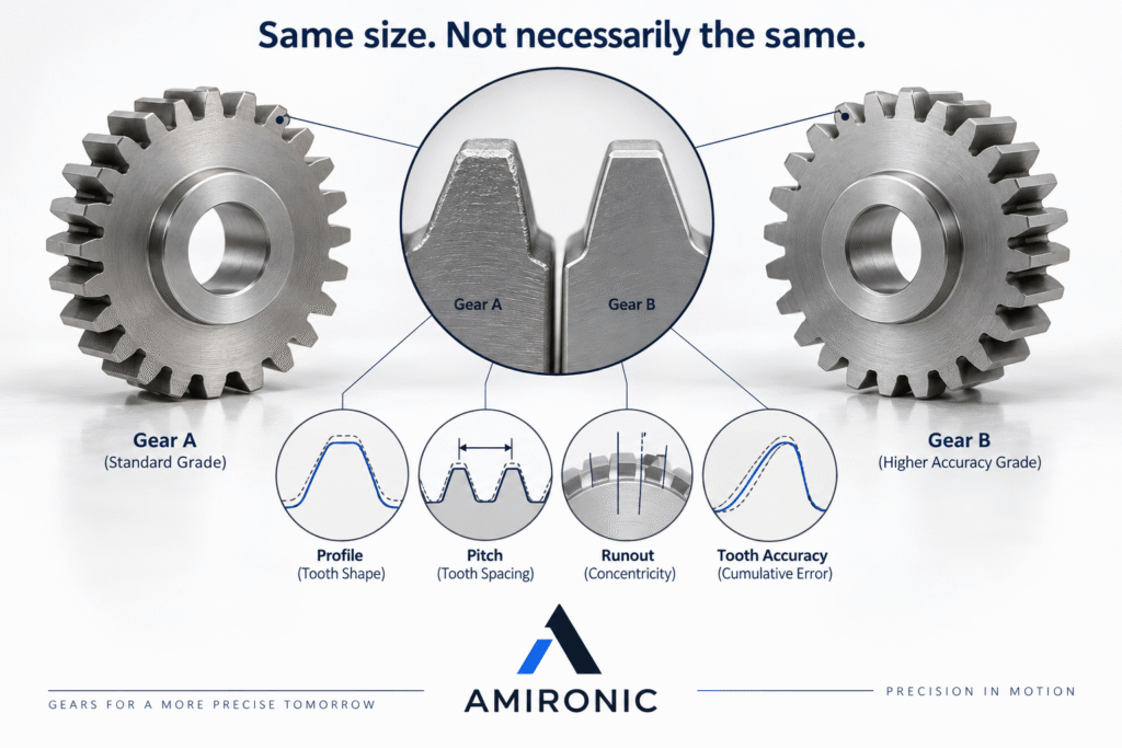
A gear is not defined only by its nominal dimensions. There are also permissible deviations in the tooth geometry and in the position of each tooth relative to the others.

Depending on the measurement method and applicable standard, parameters such as the following may be evaluated:

  • Pitch Deviations
  • Profile Deviations
  • Lead / Helix Deviations
  • Runout
  • Tooth-to-Tooth Variation
  • Composite Deviations

In practical terms, two gears can appear completely identical when measured with a caliper, yet behave differently when they rotate.

A gear with an Accuracy Grade that is not suitable for the application may result in:

  • More noise
  • More vibration
  • Positioning errors
  • Poorer load distribution
  • Increased wear
  • Less smooth operation at high speed

Not Every System Needs the Most Accurate Gear That Can Be Manufactured

This is another important point.

A gear operating in a slow, simple mechanism does not necessarily require the same Accuracy Grade as a gear used in a Positioning System, Medical System, Optical System, or high-speed mechanism.

Higher accuracy can also significantly increase manufacturing complexity and cost.

Therefore, the right question is not:

“What is the highest Grade available?”

but rather:

“What level of accuracy does the system actually require?”

This is a perfect example of a parameter that is almost impossible to reconstruct using a caliper alone.

The same nominal dimensions do not guarantee the same dynamic performance.

Step 14 – Don’t Look Only at the Gear You Want to Replace

If the gear is part of a Gear Train, it is important, whenever possible, to inspect the components that operate with it as well.

The mating gear can help verify:

  • Module
  • Pressure Angle
  • Gear Ratio
  • Center Distance
  • Contact Pattern
  • Wear Pattern

But there is another reason for doing this.

A New Gear Running Against a Worn Gear

Suppose one of the two gears is significantly worn.

We Reverse Engineer it, manufacture a new and accurate replacement gear, and install it against the existing gear.

It may seem that we have solved the problem.

Not necessarily.

The tooth profile of the old gear may already have changed from its original geometry as a result of wear. The new gear must now operate against a surface that may no longer have the profile for which it was originally designed.

This can result in:

  • Incorrect Contact Pattern
  • Uneven load distribution
  • Noise
  • Accelerated wear
  • Localized loads on the teeth
  • Reduced Service Life of the new gear

For this reason, in some cases it is better to inspect or replace the Gear Pair, rather than replacing only the component that appears to be more severely damaged.


Step 15 – Before Copying the Gear, Look at How It Failed

This may be one of the most important steps in the entire Reverse Engineering process.

Suppose the original gear arrives with worn or broken teeth.

The natural response is:

“Let’s manufacture an identical replacement.”

But before copying it, we should ask a different question:

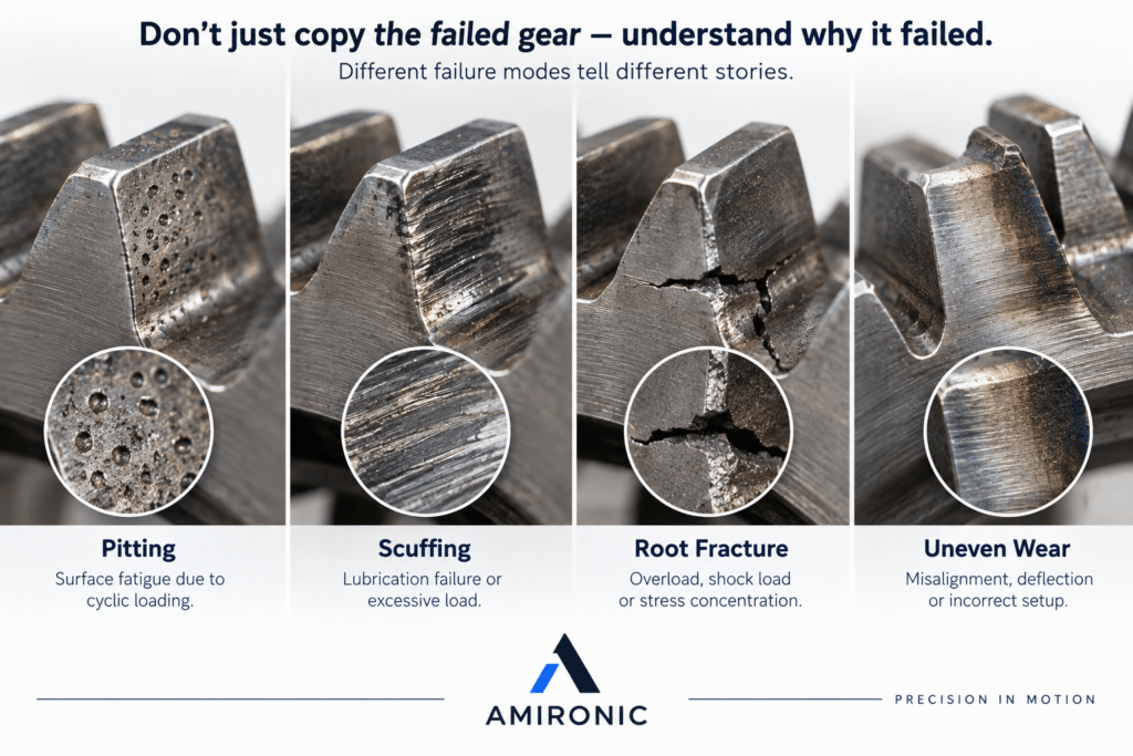
Why Did the Original Gear Fail?

A gear can sometimes tell us a great deal about what happened in the system.

Look for signs such as:

  • Pitting – small surface cavities caused by contact fatigue
  • Scoring / Scuffing – surface damage caused by sliding and severe friction at the contact surfaces
  • Spalling – localized flaking or separation of the surface material
  • Tooth Root Fracture – a fracture originating in the tooth root area
  • Wear concentrated on only one side of the tooth
  • Uneven wear across the Face Width
  • Plastic Deformation
  • Signs of overheating
  • Corrosion
  • Broken teeth

Each of these can provide a clue.

For example, wear concentrated on one side of the Face Width may indicate an Alignment problem or shaft deflection under load.

A fracture in the tooth root area may be related to:

  • Overload
  • Shock Load
  • Inappropriate Material or Heat Treatment
  • Stress concentration
  • Tooth geometry that is not suitable for the application

Abnormal wear on the tooth surface may be related to:

  • Lubrication
  • Contamination
  • Hardness
  • Surface Finish
  • Load
  • Speed
  • Contact Geometry

Sometimes the Gear Is Not the Problem – It Is Simply Where the Problem Became Visible

A Bearing problem can cause Misalignment.

A shaft that deflects under load can change the Contact Pattern.

A Housing that is not sufficiently rigid can change the Center Distance during operation.

Incorrect Lubrication can destroy a pair of gears even when their geometry is perfectly correct.

Therefore:

Don’t Reverse Engineer the Mistake.

If the gear failed because of a system-level problem, manufacturing an exact copy may simply restart the same failure process.

Sometimes the part needs to be reproduced.

And sometimes the system needs to be understood and corrected first.

What Can You Measure with a Caliper – and What Can’t You?

One simple way to summarize the identification process is to divide the information into three categories:

  1. Parameters that can be measured directly.
  2. Parameters that can be calculated or estimated from those measurements.
  3. Parameters that may require additional measurement equipment, testing, or information.
Parameter Basic Measurement Can Be Calculated / Estimated May Require Further Testing
Number of Teeth Yes – –
Outside Diameter Yes – –
Face Width Yes – –
Bore Yes – –
Hub Diameter Yes – –
Hub Length Yes – –
Keyway Yes – –
Module – Yes Sometimes
Pitch Diameter – Yes –
Center Distance Yes, in the system Yes –
Pressure Angle Not directly Sometimes Yes
Profile Shift No Sometimes Yes
Helix Angle Limited basic measurement Sometimes Yes
Material No General indication only Yes
Hardness No No Yes
Heat Treatment No Limited indication only Yes
Accuracy Grade No No Yes

This table highlights an important point:

A caliper can provide a great deal of information – but it cannot turn a gear into a manufacturing drawing.


Practical Example – A 24-Tooth Gear on the Workbench

Suppose we receive an old gear from a machine.

There is no drawing.

There is no Part Number.

There is no information about the manufacturer.

All we have is the gear itself.

Where do we start?

1. Count the Teeth

We get:

Z = 24

We still cannot determine exactly which gear it is, but we now have our first piece of information.

2. Measure the Outside Diameter

Using a caliper, we measure:

OD ≈ 52 mm

We can now make an initial estimate of the Module:

m ≈ OD / (Z + 2)

Therefore:

m ≈ 52 / 26

m ≈ 2

Our initial assumption is:

Module 2

3. Calculate the Pitch Diameter

For a standard Spur Gear:

d = m × Z

Therefore:

d = 2 × 24 = 48 mm

We now have:

  • Number of Teeth: 24
  • Estimated Module: 2
  • Outside Diameter: approximately 52 mm
  • Pitch Diameter: 48 mm

4. Continue Measuring the Gear Body

We measure:

  • Face Width
  • Bore
  • Hub Diameter
  • Hub Length
  • Overall Length
  • Keyway
  • Set Screw, if present

At this point, we have a reasonably good geometric description of the part.

Can we place an order?

Not Necessarily.

There are still important questions to answer:

What is the Pressure Angle?

Is there any Profile Shift?

Is this really a Metric Module gear rather than a Diametral Pitch gear?

What is the Material?

Have the teeth undergone Heat Treatment?

What Accuracy Grade is required?

What is the condition of the mating gear?

And what caused the original gear to reach the point where it needs to be replaced?

This is exactly where Reverse Engineering moves from simple measurement to engineering analysis.


Checklist – What Should You Send to a Gear Supplier When There Is No Drawing?

If you need a quotation for an existing gear but do not have a drawing, the more information you provide, the more uncertainty can be reduced.

Photographs

It is recommended to provide:

  • A clear photograph of both sides of the gear
  • A side view of the teeth
  • A close-up of the tooth profile
  • A photograph of the Bore and Keyway
  • A photograph of any markings, numbers, or engravings on the part
  • A photograph of the gear installed in the system, if possible

Do not send only one photograph taken from above.

An additional side-view photograph can sometimes immediately reveal that the part is a Helical Gear, show the Hub geometry, or provide useful information about the wear pattern.


Basic Dimensions

At a minimum, it is useful to provide:

  • Number of Teeth
  • Outside Diameter
  • Face Width
  • Bore Diameter
  • Hub Diameter
  • Hub Length
  • Overall Length
  • Keyway Width / Depth
  • Set Screw, if present

If you are uncertain about a particular dimension, it is better to state that it is an approximate measurement than to present it as an exact value.


Information About the Mating Gear

If you also have access to the mating gear, it is useful to provide:

  • Number of Teeth
  • Outside Diameter
  • Photographs
  • Center Distance
  • Condition and wear
  • Any existing markings or Part Numbers

Sometimes the mating gear provides exactly the missing information needed to verify the Module or understand the geometry of the system.


Application Information

This is an area that is often completely overlooked.

When trying to identify an existing gear, it is easy to focus only on dimensions.

But if the goal is to manufacture a replacement part that performs correctly, it is also important to understand what the gear actually does.

Useful information may include:

  • RPM
  • Torque
  • Gear Ratio
  • Direction of Rotation
  • Continuous / Intermittent Duty
  • Starts / Stops
  • Reversing
  • Shock Loads
  • Operating Environment
  • Temperature
  • Noise Requirements
  • Accuracy Requirements
  • Lubrication
  • Expected Operating Hours

For example, the same gear geometry may require completely different Material and Heat Treatment when operating at low speed under high load compared with a high-speed Positioning System that frequently changes direction.


When Are Simple Measurements Enough?

Not every gear requires a metrology laboratory.

For a simple, standard Spur Gear operating at low speed in a non-critical application, a few good measurements combined with correct identification of the Module and basic geometry may be enough to identify a suitable catalog part.

However, as the system becomes:

  • Faster
  • More precise
  • More heavily loaded
  • Quieter
  • Smaller
  • More critical

the accurate identification of parameters that cannot be determined with a caliper alone becomes increasingly important.

In a precision Positioning System, for example, a small Pitch or Runout deviation may be far more significant than in a slow manual mechanism.

In a Heavy-Duty system, on the other hand, Material, Heat Treatment, and load-carrying capacity may be more critical.

There is no single level of Reverse Engineering that is appropriate for every application.


What If You Simply Send the Gear Itself?

In many cases, this is the best option.

When no drawing is available and the part is sufficiently important, the existing gear can be sent for inspection and Reverse Engineering.

This allows more accurate measurements of the geometry and makes it possible to evaluate parameters that are very difficult to determine from photographs and a few basic dimensions.

If two gears operate together, there may be an advantage to inspecting both of them.

And if the gear has failed, it is best, whenever possible, to send it in its existing condition.

Do not grind the failure area or attempt to “clean” the gear in a way that removes signs of wear or damage.

Those signs may contain some of the most valuable engineering information available.

Even when sending the physical part, it is still important to provide information about the application.

The reason is simple:

Good Reverse Engineering does not ask only, “What was here?” – it also asks, “What does this part need to do?”


When Is It Better Not to Copy the Existing Part?

This may be the most important question to ask at the end of the process.

Reverse Engineering does not necessarily have to result in a 1:1 copy.

Suppose the machine was designed 25 years ago.

Since then:

  • Materials may have changed
  • Manufacturing processes may have improved
  • System requirements may have changed
  • Loads may have increased
  • Operating speeds may have changed
  • Or the original part may simply not have been optimally designed

In such a situation, it is worth asking:

Do we want to reproduce the part – or solve the problem?

Sometimes maintaining the original geometry exactly is the correct approach.

In other cases, it may be worth considering:

  • A different Material
  • A different Heat Treatment
  • A different Face Width
  • A more appropriate Accuracy Grade
  • A different shaft connection
  • A new Gear Pair
  • Or even a change to the system design

Of course, any such change requires engineering evaluation of its impact on the rest of the system.

The goal is not to arbitrarily “improve” the part.

The goal is to understand why it looks the way it does, why it performed the way it did, and what the replacement part actually needs to do.


Summary – Reverse Engineering Starts with a Caliper, but It Doesn’t End There

When no drawing is available, the gear itself contains a great deal of information.

You can count the teeth.

You can measure the Outside Diameter.

You can estimate the Module.

You can calculate the Pitch Diameter.

You can measure the Bore, Hub, Face Width, and Keyway.

And if the mating gear and Center Distance are available, additional checks can be performed to support – or challenge – our initial assumptions.

But some parameters should not simply be guessed.

Pressure Angle, Profile Shift, Material, Heat Treatment, Hardness, and Accuracy Grade can be just as critical as the Number of Teeth and diameter.

And even after identifying the gear itself, one question remains:

Why does it need to be replaced in the first place?

If the system has an Alignment problem, Bearing problem, incorrect Lubrication, Shock Loads, or unsuitable loading conditions, simply copying the gear may not solve the underlying problem.

The purpose of Reverse Engineering is therefore not merely to manufacture a part that looks like the original.

The goal is to produce:

A gear that is geometrically correct, mounts correctly, meshes correctly with the mating gear – and performs correctly in the actual system.


Do You Have an Existing Gear but No Drawing?

Send us clear photographs, the Number of Teeth, basic dimensions, and information about the application.

If necessary, the existing part and mating gear can also be inspected to assist with the identification and Reverse Engineering process.

Because when it comes to gears:

“Looks the same” and “works the same” are not always the same thing.

Further Reading

For a broader understanding of motion transfer system design and the role of gears and couplings in overall system behavior, the following articles provide additional engineering insights:

  • Gears & Couplings: An Engineering Guide to Precision Motion Transfer

  • How to Choose the Right Coupling Without Guessing

  • Common Coupling Failures and How to Prevent Them

  • Gear Material Selection Guide: Strength, Wear, Corrosion & Environment – How to Choose Correctly

  • Backlash Is Not a Number: Understanding What Really Determines Accuracy, Stability, and System Life

  • Spur, Helical and Worm Gears – Engineering Differences and How to Choose the Right One

  • Backlash in Gears – From Geometry to System Behavior: Understanding what really happens between gear teeth
  • Small Spur Gears: Why Miniaturization Creates Hidden Mechanical Problems
  • Gear Hardening Explained – Why Case Hardened Gears Dominate Heavy Duty Power Transmission
  • Why a Million-Dollar Medical System Still Uses Rack & Pinion
  • Why Most Engineers Use Bevel Gears for Only 10% of What They Can Actually Do
  • Why the Number of Starts in a Worm Gear Matters More Than the Gear Ratio
  • The Gearbox Isn’t the Problem – It’s Simply the First to Pay for Design Mistakes
  • When the System Starts to Vibrate – Don’t Rush to Retune the Motion Controller
  • How to Calculate Gear Ratio and Choose the Right Gears
  • “I Have a 24-Tooth Gear. Send Me the Same One.”

Frequently Asked Questions – FAQ

How Do You Identify a Gear When There Is No Drawing?

Identifying a gear without a drawing usually begins by determining the gear type – Spur Gear, Helical Gear, Bevel Gear, Worm Gear, or another type – and then measuring the Number of Teeth, Outside Diameter, Face Width, Bore, Hub, and Keyway.

For a standard Spur Gear, it may sometimes be possible to estimate the Module from the Number of Teeth and Outside Diameter.

However, full Reverse Engineering may also require identification of the Pressure Angle, Profile Shift, Material, Heat Treatment, and Accuracy Grade.

How Do You Measure the Module of an Existing Gear?

For a standard Metric Spur Gear, an initial estimate of the Gear Module can be made using the Number of Teeth Z and the Outside Diameter OD:

m ≈ OD / (Z + 2)

For example, if the gear has 24 teeth and an Outside Diameter of approximately 52 mm:

m ≈ 52 / 26 = 2

It is therefore reasonable to investigate whether the gear is a Module 2 Gear.

However, this calculation is not proof when Profile Shift, significant wear, or non-standard geometry is present.

How Do You Measure a Gear with a Caliper?

A caliper can be used to measure many parameters of an existing gear, including Outside Diameter, Bore Diameter, Face Width, Hub Diameter, Hub Length, Overall Length, and Keyway.

You can also count the Number of Teeth and combine these measurements to estimate the Module and Pitch Diameter.

However, parameters such as Pressure Angle, Accuracy Grade, Heat Treatment, and precise tooth-profile geometry generally cannot be identified reliably with a caliper alone.

How Do You Calculate the Pitch Diameter of a Gear?

For a standard Metric Spur Gear:

Pitch Diameter = Module × Number of Teeth

or:

d = m × Z

For example, for a Module 2 gear with 24 teeth:

d = 2 × 24 = 48 mm

It is important to remember that Pitch Diameter is a theoretical geometric diameter, not a physical surface that can be measured directly with a standard caliper.

How Do You Know Whether a Gear Uses Module or Diametral Pitch?

Metric gears are generally specified using Module, while Imperial systems may use Diametral Pitch – DP.

If the dimensions of an existing gear do not correspond well with a standard Module, particularly in an older American or British machine, it is worth checking whether the gear is specified in DP.

The approximate relationship is:

Module = 25.4 / DP

Therefore:

DP = 25.4 / Module

What Is the Difference Between Module and Pitch Diameter?

Module defines tooth size in relation to the Pitch Diameter and Number of Teeth.

Pitch Diameter is the theoretical diameter used to describe the meshing action and geometric relationship between gears.

For a Metric gear, the relationship is:

d = m × Z

Two gears that mesh with each other must have compatible tooth geometry. Matching Module is a key requirement, but it is not the only parameter that must be checked.

How Do You Identify the Pressure Angle of a Gear?

The Pressure Angle cannot be determined reliably from the Number of Teeth and Outside Diameter alone.

For more accurate identification, methods such as Span Measurement, Measurement Over Pins/Wires, Gear Tooth Vernier measurements, optical measurement, CMM, or dedicated gear measurement equipment can be used.

A 20° Pressure Angle is very common in modern gears, but it should not automatically be assumed that every existing gear uses 20°.

Can Two Gears with the Same Module Still Be Incompatible?

Yes.

Two gears with the same Gear Module may still be incompatible if they differ in Pressure Angle, Helix Geometry, Profile Shift, or other tooth-profile parameters.

For Helical Gears, the Helix Angle, Helix Direction, and the appropriate definition of Normal/Transverse Module must also be checked.

What Is Profile Shift in a Gear?

Profile Shift, also known as Addendum Modification, is a change in the relative position of the cutting tool when generating the tooth profile.

It can affect Tooth Thickness, Root Thickness, Outside Diameter, Undercut, and Contact Geometry.

As a result, a gear with Profile Shift may not correspond exactly to the simple formulas used for a Standard Spur Gear.

How Do You Identify a Helical Gear Compared with a Spur Gear?

In a Spur Gear, the teeth are straight and parallel to the axis of rotation.

In a Helical Gear, the teeth are angled relative to the axis.

When identifying a Helical Gear, it is also necessary to check the Helix Angle, tooth direction – Right-Hand or Left-Hand – and the appropriate Module definition.

The simple formulas used for Spur Gears should not automatically be applied when Reverse Engineering a Helical Gear.

Can You Identify Gear Material by Appearance?

It may sometimes be possible to determine generally whether a gear is made from Steel, Bronze, Brass, or Plastic.

However, the exact Material Grade usually cannot be identified from appearance alone.

When the material affects strength, wear, or Service Life, it is better to rely on a drawing, manufacturer information, or appropriate material testing.

How Can You Tell Whether a Gear Has Been Hardened?

The type of Heat Treatment cannot be determined reliably using a caliper or visual inspection alone.

Gears may be Through Hardened, Case Hardened, Induction Hardened, or Nitrided.

When necessary, Hardness Testing and additional material tests can be performed.

Can Reverse Engineering Be Performed on a Broken Gear?

Yes.

In many cases, much of the original geometry can still be reconstructed even when some of the teeth are damaged.

It is best to preserve the part in its existing condition and, if possible, also provide the mating gear, photographs of the system, and information about the application.

Signs of Pitting, Scuffing, Root Fracture, or Uneven Wear may also help identify the cause of failure.

Should You Replace Only the Broken Gear?

Not always.

If the mating gear is significantly worn, installing a new Gear against a worn tooth profile may result in an incorrect Contact Pattern, noise, localized loading, and accelerated wear.

In such cases, it is advisable to inspect both gears and the overall system before deciding whether to replace a single component or the complete Gear Pair.

What Information Should Be Sent to Request a Gear Quotation Without a Drawing?

At a minimum, it is useful to provide Number of Teeth, Outside Diameter, Face Width, Bore Diameter, Hub dimensions, and Keyway dimensions, together with clear photographs of both sides of the gear and the teeth.

Information about Module, Pressure Angle, Material, Heat Treatment, RPM, Torque, Gear Ratio, Center Distance, and the mating gear can significantly improve both the identification process and the accuracy of the quotation.


Important Terms in Gear Identification and Measurement

Gear
A mechanical component with teeth used to transmit motion and torque between shafts, or between rotary and linear motion.

Spur Gear
A gear with straight teeth that are parallel to the axis of rotation. It is one of the most common gear types and is relatively straightforward to measure and identify.

Helical Gear
A gear in which the teeth are angled relative to the axis. Its geometry includes additional parameters such as Helix Angle and Right-Hand or Left-Hand direction.

Reverse Engineering
The process of analyzing and measuring an existing component in order to understand its geometry, Material, characteristics, and performance requirements, particularly when the original drawing is unavailable.

Number of Teeth – Z
The total number of teeth on a gear. It is a basic parameter used in calculating Gear Ratio, Pitch Diameter, and other geometric characteristics.

Module
A key Metric parameter used to describe tooth size. For a Metric gear:

m = d / Z

where d is the Pitch Diameter and Z is the Number of Teeth.

Diametral Pitch – DP
An Imperial method of defining tooth size. Unlike Module, a higher DP value represents smaller teeth.

Outside Diameter – OD
The outside diameter of the gear, measured across the tips of opposite teeth.

Pitch Diameter
A theoretical geometric diameter used to define the meshing relationship and motion between gears.

For a standard Metric gear:

d = m × Z

Pressure Angle
An angle associated with the tooth-profile geometry and the direction of force transmission between mating gears.

20° is very common, although other Pressure Angles are also used.

Involute Profile
A widely used gear tooth profile that allows transmission of motion at a constant velocity ratio when the geometry and assembly are correct.

Profile Shift
A modification in the cutting position relative to the standard tooth geometry.

It may be used to alter tooth strength, prevent Undercut, or adapt the geometry of a mating gear pair.

Undercut
Removal of material near the tooth root as a result of the generating geometry, particularly in gears with a low Number of Teeth.

Significant Undercut can weaken the tooth root.

Face Width
The width of the toothed portion of the gear along its axis.

This parameter influences, among other things, the available contact area and load-carrying capacity.

Bore Diameter
The diameter of the central hole through which the gear is typically mounted on a shaft.

Hub
The raised central portion of a gear around the Bore, often used to connect the gear to the shaft and provide the required mounting length.

Keyway
A slot in the gear and shaft that allows a Key to transmit torque and prevent relative rotation between them.

Center Distance
The distance between the centers of the two shafts on which the gears are mounted.

For a standard pair of external Spur Gears, it is related to the Pitch Diameters of the two gears.

Helix Angle
The angle at which the teeth of a Helical Gear are inclined relative to the axis.

It affects tooth geometry, contact conditions, and the forces generated in the system.

Gear Ratio
The relationship between the rotational speeds or Number of Teeth of two meshing gears.

For a simple gear pair, the ratio is determined by the Number of Teeth of the two gears.

Backlash
The clearance between mating tooth surfaces when a pair of gears is engaged.

Backlash affects motion, accuracy, Lubrication, thermal expansion, and system behavior during changes in direction.

Runout
A cyclic deviation of the gear relative to the axis of rotation, which may result from manufacturing geometry or the way the gear is mounted.

Accuracy Grade
A classification of the geometric accuracy of a gear according to the applicable standard and measured parameters.

Accuracy Grade can affect noise, vibration, operating speed, and motion accuracy.

Heat Treatment
A process used to modify the mechanical properties of a Material, including Hardness, Wear Resistance, and Fatigue Strength.

Case Hardening
A process in which a relatively hard surface layer is produced while maintaining different mechanical properties in the core, depending on the Material and treatment process.

Pitting
Localized damage in the form of small cavities on the tooth surface, usually caused by cyclic contact fatigue.

Scuffing / Scoring
Damage to the contacting surfaces that may occur when Lubrication conditions, load, temperature, or speed result in excessive sliding and surface distress.

Root Fracture
A fracture that begins in the tooth root area, where significant bending stresses can develop.

Contact Pattern
The actual area over which the tooth surfaces of two mating gears come into contact.

An incorrect Contact Pattern may indicate Misalignment, incorrect geometry, or installation problems.

Tags: Amironic

Related Articles

Gears & Couplings: An Engineering Guide to Precision Motion Transfer

10/02/2026amironicLTD

Upgrading Commercial Electronics for Airborne Military Platforms

25/01/2026amironicLTD

Designing Power Architectures for MIL-STD-1275E/F Military Vehicle Systems

16/03/2026amironicLTD

Recent Posts

  • Military Temperature Sensors – How to Choose the Right Temperature Sensor for Harsh Environments?
  • How to Identify an Existing Gear Without a Drawing – A Practical Measurement Guide for Engineers
  • Standards for Power Supplies and DC-DC Converters – A Guide to Military, Aerospace, and Automotive Applications
  • How to Choose an IMU for a Dynamic System – Why “More Accurate” Doesn’t Always Mean “Better”
  • Electrical, Pneumatic, USB, Bluetooth or Contactless – How Do You Choose the Right Switch for Your System?

Categories

  • Air Switch
  • Circuit Breakers
  • Elapsed Time Indicator
  • Feedthrough
  • Footswitches
  • Gears & Transmission
  • Hour Meters
  • Infra Red Switches
  • INFRARED LAMPS
  • Low Noise Inertial MEMS
  • Mechanics
  • MEMS Gyroscope
  • MEMS Inertial
  • Microelectronics
  • Motors
  • Position Sensors
  • Power Supply
  • Pressure Sensors
  • Pressure Switch
  • Temperature Sensors
  • Tungsten and Molybdenum
  • Uncategorized
  • Vacuum Switches

Quick Contact

Fill out the form and our representatives will return to you

    Name (required)

    Email (required)

    Phone

    Message

    This site is protected by reCAPTCHA and the Google
    Privacy Policy and
    Terms of Service apply.

    Amironic Ltd.

    3 Rabinovich Street, Petah Tikva 4928144 , Israel. Tel: +972-3-9047744 E-mail: office@amironic.co.il
    Email
    Facebook
    Twitter
    LinkedIn
    YouTube
    Press on the ISO Certificate below for download
    ISO 9001:2015 Certification
    • MEMS Inertial
    • Circuit Breakers
    • Footswitches
    • Mechanical & Transmisions
    • Sensors
    • Motors
    • Electronics
    • Hand Control
    • Power Solutions

    News

    • Military Temperature Sensors – How to Choose the Right Temperature Sensor for Harsh Environments?
    • How to Identify an Existing Gear Without a Drawing – A Practical Measurement Guide for Engineers
    • Standards for Power Supplies and DC-DC Converters – A Guide to Military, Aerospace, and Automotive Applications
    • How to Choose an IMU for a Dynamic System – Why “More Accurate” Doesn’t Always Mean “Better”
    • Electrical, Pneumatic, USB, Bluetooth or Contactless – How Do You Choose the Right Switch for Your System?
    About AmironicContactעברית
    © 2022 Amironic All rights reserved. All Trademarks are the property of their respective owners.
    • Increase Font
    • Decrease Font
    • Black & White
    • Inverse Colors
    • Highlight Links
    • Regular Font
    • Reset