flagעברית
flagEnglish
3 Rabinovich St., Petah-Tikva, Israel
+972 3 9047744
office@amironic.co.il
Facebook
Twitter
LinkedIn
YouTube
  • Products
    • MEMS Inertial
      • MEMS Gyroscopes
      • Inertial Measurement Units
      • MEMS Accelerometers
      • Inertial Navigation
      • AHRS
    • Circuit Breakers
      • Airpax Circuit Breakers
      • Electronic Circuit Breakers
      • Aircraft Circuit Breakers
      • Thermal Circuit Breakers
      • Sealing Solutions & Guards
    • Footswitches
      • Pedals & Bellows
      • USB
      • Air Switches
      • Medical
      • Modular Bases System
      • Industrial
      • Foot Potentiometers
      • Wireless
    • Mechanical & Transmissions
      • Gears
      • Sealing Solutions
      • Gearboxes
      • Couplings
      • Shafts & Bearings
      • Fasteners
      • Mechanical & Springs
      • Linear Motion
      • Anti-Vibration
    • Sensors
      • Thermostats
      • Temperature
      • Position
      • Pressure
      • Speed
      • Level Sensor
      • Load Cells
      • Flex Sensors
      • Membrane Potentiometer
    • Motors
      • Geared DC
      • Brushless DC
      • Step Motors with Gearbox
      • Torque Motors & Brushless Servo
      • DC Motors
    • Electronics
      • Xenon & IR Lamps
      • Counters & Meters
      • Microelectronics Packaging
      • Waterproof Switches
      • Micro Switches
    • Hand Control
      • Operator Controls (JOYSTICK)
      • Electrical
      • Pneumatic (Medical)
      • USB Hand Control
      • Air Push Button
      • Pressure Switch
      • IR Switch
    • Power Solutions
      • Rugged & Military Power Supply
      • Input Power Protection
      • Sealed Military Power Adaptor
      • Triple Output Military Power Supply Series – up to 250 W
    • Materials
      • Molybdenum and Advanced Alloys (TZM, MOLA, HCT)
      • Tungsten (Wolfram) and Advanced Alloys – High-Performance Materials for Extreme Conditions
      • Materials for Gears
  • Shop
  • Companies
  • About Amironic
  • News
  • Contact
Product was added to your cart

Cart

waze

Pneumatic Switches for Wet Environments – Operating Principles, Electrical Separation, and Applications in Pools, Spas, and Humid Environments

Air Switch04/11/2026amironicLTD

1. Introduction – How Can Electrical Equipment Be Operated in Wet Environments?

Operating electrical equipment in wet or humid environments presents significant engineering challenges. Swimming pools, spas, hot tubs, bathrooms, industrial washdown systems, and medical equipment exposed to liquids require control solutions that combine reliability, ease of use, and electrical safety.

In conventional electrical control systems, pressing a button changes the state of electrical contacts or activates an electronic sensor. When the push button is installed in an area exposed to water, potential risks include liquid ingress, corrosion, deterioration of electrical insulation, and wear caused by prolonged exposure to moisture and cleaning chemicals.

Even when using a push button with a high ingress protection (IP) rating, proper electrical design, suitable material selection, and compliance with applicable safety standards remain essential.

One effective solution for these applications is a pneumatic switch, which allows a control signal to be transmitted through air pressure rather than an electrical connection at the point of actuation.

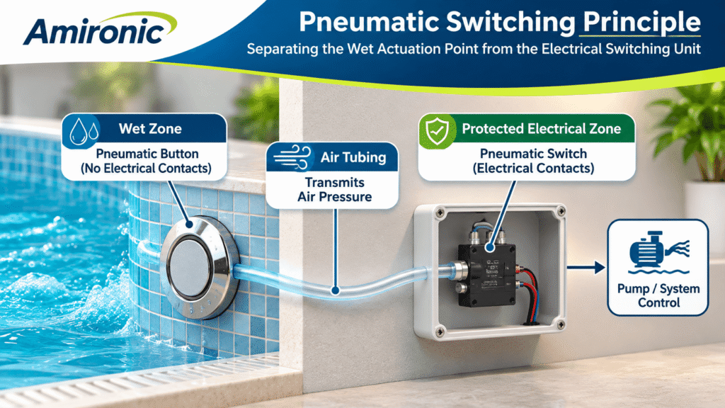
In a typical pneumatic switching system, the operator presses a push button connected to an air tube. The resulting pressure change travels through the tubing to an electrical switching unit installed in a separate, protected location.

This arrangement allows the push button to be positioned in a wet environment while keeping electrical contacts and wiring away from areas directly exposed to water.

The key advantage of pneumatic switching technology is the ability to physically separate the point of actuation from the electrical switching mechanism, eliminating the need for electrical wiring at the push button itself.

UK-based HERGA Technology specializes in the development and manufacture of switching and control solutions for industrial and medical applications. Its product portfolio includes pneumatic switches, hand controls, and actuation systems designed for use in wet and humid environments.

In this article, we will explore the operating principles of pneumatic switches, explain the significance of physical separation between the actuator and electrical contacts, examine the advantages and limitations of the technology, and discuss key engineering considerations when selecting suitable solutions for spas, swimming pools, and industrial applications.

Important: Pneumatic separation does not, by itself, constitute certified electrical isolation or guarantee electrical safety. The complete system must comply with all applicable electrical safety, installation, and regulatory requirements.
2. Operating Principles of Pneumatic Switches – How Does Air Pressure Become an Electrical Command?

A pneumatic switch enables an electrical circuit to be operated through a change in air pressure, without requiring an electrical connection at the point of actuation.

The principle is based on separating two functions: generating a control signal through air pressure and converting that signal into an electrical switching action at a separate location.

Unlike industrial pneumatic systems that use compressed air to operate cylinders or motors, a basic pneumatic switching system does not require a compressor or an external pressure source. Pressing the push button generates the pressure change needed for actuation.

2.1 Main Components of a Pneumatic Switching System

A typical system consists of three main components:

A. Pneumatic Push Button / Air Actuator

This is the component pressed by the operator.

Inside the push button, a flexible air chamber or mechanical mechanism changes the enclosed air volume when pressed. This volume change generates a pressure variation that is transmitted through the system.

The push button itself contains no electrical contacts, eliminating the need to run electrical wiring to the point of actuation.

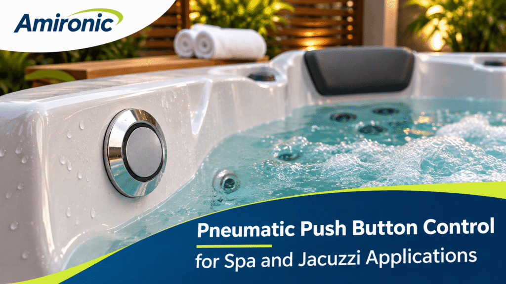
Depending on the model and installation requirements, pneumatic push buttons can be mounted on spa walls, control panels, and other locations exposed to water splashes or high humidity.

However, suitability for direct water exposure, immersion, or contact with cleaning chemicals must always be verified against the manufacturer’s specifications.

B. Pneumatic Tubing

The pneumatic tubing connects the push button to the electrical switching unit.

Its function is to transmit the pressure change generated by the push button without carrying electrical current.

The tubing allows the switching unit to be installed away from the point of actuation, for example, inside a protected electrical control enclosure.

It is important to understand that tubing length is not unlimited. As the total air volume within the system increases, the switch response to actuation may change.

The tubing’s internal diameter, flexibility, connection integrity, and temperature variations can also affect system performance.

Therefore, tubing specifications and length should be selected according to the manufacturer’s recommendations and the requirements of the complete system.

C. Air-Operated Electrical Switch

The air-operated electrical switch converts the pneumatic pressure signal into an electrical switching action.

When the pressure change reaches the switching unit, an internal mechanism, such as a diaphragm or pressure-sensitive mechanical assembly, actuates the electrical contacts.

Depending on the model, the switch may offer different contact configurations, including:

  • Normally Open (NO): A contact that is open in its normal state and closes when actuated.
  • Normally Closed (NC): A contact that is closed in its normal state and opens when actuated.
  • Changeover (SPDT): A single-pole, double-throw contact arrangement that switches between two electrical paths.

The availability of these configurations depends on the specific switch model.

The electrical switching unit is installed in a location suitable for the applicable environmental and safety requirements. It can be connected to a controller, relay, or another control system.

2.2 What Happens When the Operator Presses the Button?

Consider a simple example of operating a hot tub pump using a pneumatic push button.

Step 1 – Pressing the Push Button

The operator presses a pneumatic push button installed on the wall of the hot tub.

Pressing the button changes the volume of the internal air chamber, generating a pressure change.

Step 2 – Transmitting the Pressure Signal

The pressure change travels through the pneumatic tubing to the switching unit.

At this stage, no electrical signal is transmitted from the push button to the switching unit. The command is conveyed entirely through air pressure.

Step 3 – Actuating the Switch

The switching unit responds to the pressure change and activates its internal electrical switching mechanism.

The electrical contacts change state according to the switch configuration.

Step 4 – Activating the Control System

The control system detects the change in contact state and activates the pump, either directly or through a suitable relay or contactor.

For applications involving high operating currents, the load must not be connected directly to the pneumatic switch unless its contact ratings explicitly support the load and its electrical characteristics.

Step 5 – Releasing the Push Button

When the operator releases the push button, the air pressure may return to its initial level.

The resulting electrical response depends on the switching mechanism and the control system design.

2.3 Momentary vs. Latching Operation

Not all pneumatic switching systems operate in the same way.

Two common operating modes are particularly important:

Momentary Operation

In a momentary switching system, the electrical contacts change state while the required actuation condition is present.

When the pressure returns to its resting level, the contacts return to their original state.

This operating mode is suitable for applications requiring momentary commands, such as triggering a controller input or issuing a start command.

Latching / Alternate Action

In a latching or alternate-action switching system, one actuation changes the switching state, and a subsequent actuation returns it to the previous state.

For example:

  • First press: The hot tub pump turns ON.
  • Second press: The hot tub pump turns OFF.

It is important to distinguish between a switch with a built-in mechanical latching mechanism and a system in which the ON/OFF function is managed by an electronic controller or a suitable relay.

Not every pneumatic switch includes an integrated latching mechanism.

2.4 Does a Pneumatic Switch Require a Compressed Air Supply?

Not necessarily.

In manually operated pneumatic switching systems, pressing the push button generates the pressure change required for actuation.

No compressor, compressed air reservoir, or industrial pneumatic infrastructure is needed.

This is a significant advantage in applications requiring a simple control command without the complexity of a compressed air system.

However, it is important to distinguish between switches actuated by an air-pressure pulse generated by a push button and pneumatic pressure switches designed to monitor pressure within a system.

Although both types respond to pressure, they are not necessarily intended for the same applications.

2.5 Important Engineering Consideration – Physical Separation Is Not Necessarily Certified Electrical Isolation

The main advantage of pneumatic switching is the ability to position electrical contacts away from the point of actuation.

However, physical separation must not be confused with electrical insulation or isolation that meets the requirements of a specific safety standard.

The absence of electrical wiring at the push button does not, by itself, guarantee that the complete system is safe for use in a wet environment.

The following must still be verified:

  • The electrical switching unit is installed in a suitably protected location.
  • The system complies with the applicable electrical safety and installation requirements for swimming pools, spas, or the relevant application.
  • The electrical contact ratings are suitable for the operating voltage, current, and load type.
  • The push button, tubing, and connections are compatible with the environmental conditions.
  • Appropriate electrical protection measures are incorporated into the complete system.

Engineering Rule of Thumb: A pneumatic switch allows the point of actuation to be physically separated from the electrical switching mechanism. It does not replace proper electrical safety design or compliance with applicable standards.

3. Advantages and Limitations of Pneumatic Switches in Wet Environments

The use of pneumatic switches in wet environments is not solely about protecting electrical components from water. The technology offers a different design approach, allowing the user interface to be physically separated from the electrical switching system.

This separation can simplify the design of the actuation point, reduce the exposure of electrical components to harsh environmental conditions, and provide greater flexibility in positioning control components.

However, like any switching technology, pneumatic systems have both advantages and engineering limitations that must be considered.

3.1 Separation Between the Point of Actuation and Electrical Contacts

The most significant advantage of a pneumatic switch is the ability to position the push button in a wet environment while keeping the electrical contacts in a separate location.

In a conventional electrical switching system, the push button may contain electrical contacts, wiring, or electronic components. These components require appropriate protection when installed in areas exposed to water.

In a pneumatic system, the push button itself does not need to contain electrical components. Instead, the operator’s command is transmitted through a change in air pressure.

For example, in a spa installation, a pneumatic push button can be mounted on the wall of the tub, while the electrical switching unit is located inside a suitable control enclosure, away from the wet area.

This arrangement allows electrical contacts to be positioned away from the area where the user is in contact with water.

Important: This physical separation is a design advantage, but it does not eliminate the need for electrical protection, proper installation, or compliance with applicable safety standards.

3.2 Reduced Exposure of Electrical Components to Moisture and Corrosion

High humidity, water splashes, steam, and cleaning chemicals can affect electrical components over time.

Potential failure mechanisms include:

  • Corrosion of electrical contacts and connectors.
  • Moisture ingress into enclosures and connections.
  • Deterioration of electrical insulation.
  • Formation of unintended conductive paths due to moisture and contaminants.
  • Failures caused by repeated exposure to water and cleaning chemicals.

In a pneumatic switching system, the electrical switching unit can be installed away from areas directly exposed to water.

This may reduce the exposure of electrical components to these conditions and contribute to improved long-term system reliability.

However, the pneumatic components themselves must also be suitable for the operating environment.

Prolonged exposure to chlorine, disinfectants, ultraviolet (UV) radiation, or elevated temperatures may affect the materials used in the push button, seals, and pneumatic tubing.

Therefore, not every pneumatic push button should automatically be considered suitable for every swimming pool or spa environment.

3.3 Greater Flexibility in Positioning the Switching Unit

In many systems, the most convenient location for the operator is not necessarily the most suitable location for electrical components.

For example, in a hot tub, the user may need to activate the pump from inside the tub, while the electrical control system is installed in a technical room or service enclosure.

A pneumatic switching system allows these two locations to be connected through an air tube.

This separation can simplify system design and provide more convenient access to electrical switching components for maintenance.

However, the distance between the push button and the switching unit must be treated as an engineering parameter.

Tubing length, internal diameter, total air volume, and material flexibility can affect the pressure signal reaching the switch and the overall system response.

Engineering Rule of Thumb: Do not select pneumatic tubing length based solely on the physical distance between components. Verify that the combination of push button, tubing, and switching unit is suitable for the required distance according to the manufacturer’s specifications.

3.4 Operation Without Electrical Voltage at the Push Button

One of the key characteristics of a pneumatic push button is that it does not require an electrical power supply at the point of actuation.

The operator activates a mechanical mechanism that generates a change in air pressure rather than operating a local electrical circuit.

This can be particularly advantageous in systems where electrical wiring at the user interface is undesirable.

However, the absence of an electrical connection at the push button must not be confused with the overall electrical safety of the system.

Swimming pool and spa installations still contain electrical components such as pumps, heaters, controllers, and relays.

These components require appropriate electrical design and protection in accordance with the standards applicable to the installation.

3.5 A Simple Solution Without a Compressor

In many manually operated pneumatic switching systems, pressing the push button generates the pressure change required for actuation.

As a result, no compressor or external compressed air supply is needed.

A basic system may consist of only three components: a pneumatic push button, air tubing, and an air-operated electrical switch.

This simplicity can be particularly useful in applications requiring basic ON/OFF control without complex signal transmission or continuous control functions.

However, applications requiring variable speed control, proportional operation, or data communication may require additional or alternative control technologies.

3.6 Engineering Limitations and Challenges

Despite their advantages, pneumatic switches are not a universal solution.

Several limitations must be considered during system design.

A. Sensitivity to Air Leaks

A leak in the tubing or at a connection may weaken the pressure signal, resulting in inconsistent actuation or complete failure to operate.

B. Tubing Length Limitations

Excessively long tubing, or tubing with unsuitable characteristics, may affect switch response and operating reliability.

C. Environmental Influences

Temperature, humidity, chemical exposure, and aging of tubing and push button materials can influence system performance over time.

D. Functional Limitations

A basic pneumatic switch is generally intended to transmit a switching command. It does not necessarily provide feedback about the system’s operating state or support continuous control.

E. Maintenance and Troubleshooting

When a fault occurs, troubleshooting must include not only the electrical switching unit but also the push button, pneumatic tubing, connections, and overall system airtightness.

F. Suitability for Safety Functions

A standard pneumatic switch must not be used as a safety device, such as an emergency stop switch, unless the complete safety function has been properly designed and validated for that purpose.

3.7 When Is a Pneumatic Switch the Right Choice?

Pneumatic switches may be suitable when one or more of the following conditions apply:

  • The point of actuation is exposed to water or high humidity.
  • Electrical contacts should be kept away from the operator’s control point.
  • A simple and reliable switching command is required.
  • The electrical switching unit can be installed in a protected and accessible location.
  • The distance between the push button and switching unit is within the manufacturer’s specified operating limits.
  • Environmental conditions are compatible with the materials used in the push button, tubing, and seals.

Conversely, applications requiring continuous control, digital communication, detailed feedback, or integration with advanced control systems may also require electrical or electronic control solutions.

Engineering Conclusion: The primary advantage of pneumatic switching is not that it replaces the electrical control system. Rather, it allows electrical switching components to be positioned away from the point of actuation, enabling a simple user interface that is well suited to wet environments.

4. HERGA Pneumatic Switches – Practical Solutions for Swimming Pools, Spas, and Wet Environments

HERGA Technology offers a comprehensive range of pneumatic switches, air-operated push buttons, pressure switches, and air-operated electrical switching units.

These solutions serve a wide variety of applications, from spas and hot tubs to medical equipment, public bathing facilities, and industrial machinery.

One of the key advantages of HERGA’s product range is the ability to select the pneumatic actuator and electrical switching unit separately, allowing the complete system to be configured according to its mechanical, electrical, and environmental requirements.

4.1 HERGA 6438 Pneumatic Push Buttons – Compact Solutions for Spas and Hot Tubs

The HERGA 6438 Mini Push Button Switches series includes compact pneumatic push buttons designed for applications that may involve exposure to moisture.

The series is available in nominal diameters of 38 mm and 50 mm and is suitable for applications requiring a simple user interface without electrical contacts at the point of actuation.

One typical application is controlling water jets in spas and hot tubs.

The push button is installed on the wall of the spa or in a suitable control panel. When pressed, it generates an air-pressure signal that travels through pneumatic tubing to a switching unit installed in a protected location.

Key Advantages of HERGA 6438:

  • Compact design suitable for integration into control panels.
  • Relatively low profile above the mounting surface.
  • Pneumatic operation without electrical contacts in the push button.
  • Suitability for humid environments, depending on the specific model and installation conditions.
  • Compatibility with appropriately selected HERGA air-operated switching units.

When Should You Consider HERGA 6438?

The HERGA 6438 is a suitable starting point when designing a spa, hot tub, or advanced shower system that requires a relatively small, convenient push button integrated into the mounting surface.

It is particularly worth considering when appearance, available installation space, and the absence of electrical components at the point of actuation are important design considerations.

4.2 HERGA 6442 Pneumatic Push Buttons – When Greater Air Volume Is Required

The HERGA 6442 Large Push Button Switches series features pneumatic push buttons with a relatively large air displacement volume.

This characteristic can be particularly important in systems where the distance between the push button and the electrical switching unit is significant.

When a pneumatic push button is pressed, the displaced air volume influences the pressure signal transmitted through the tubing.

In systems with long tubing runs, the total enclosed air volume and the flexibility of the components can affect the pressure signal reaching the switching unit.

A push button capable of displacing a greater volume of air may help achieve reliable actuation when combined with a switching unit of suitable sensitivity.

Key Advantages of HERGA 6442:

  • Relatively large air displacement volume.
  • Potential suitability for longer pneumatic tubing runs when paired with an appropriate switching unit.
  • Various construction and material options.
  • Suitable for applications requiring clear and convenient mechanical actuation.

When Should You Consider HERGA 6442?

The HERGA 6442 is worth considering when the push button is located at a significant distance from the control enclosure, such as in a commercial spa installation where electrical components are housed in a separate technical room.

However, the maximum permissible tubing length cannot be determined from air displacement volume alone. The complete combination of push button, tubing, and switching unit must be evaluated.

4.3 HERGA 6871 and 6872 Air Switches – Compact Solutions for OEM Equipment

The HERGA 6871 and HERGA 6872 series consist of air-operated electrical switches designed to convert a pneumatic pressure signal into an electrical switching action.

Unlike the 6438 and 6442 pneumatic push buttons, these units contain the electrical switching mechanism and are installed on the electrical side of the system.

Their compact and cost-effective construction makes them particularly suitable for integration into OEM equipment.

Depending on the specific model and configuration, available options include:

  • Momentary switching operation.
  • Latching or alternate-action switching.
  • Rear or side pneumatic tubing connections.
  • Versions with UL/CSA approvals, subject to the specific part number.

Application Example:

A hot tub manufacturer wants to switch a circulation pump ON and OFF using a pneumatic push button installed on the wall of the tub.

One possible approach is to evaluate a HERGA 6438 pneumatic push button combined with a suitable switching unit from the 6871 or 6872 series.

If alternate ON/OFF operation using a single push button is required, an appropriate latching version may be considered.

If the control system requires a momentary input signal, a momentary switching version may be more suitable.

The final selection depends on the electrical contact ratings, load characteristics, switching configuration, and pneumatic compatibility between the components.

4.4 HERGA 6861–6869 Air Switches – Flexibility in Control System Design

The HERGA 6861–6869 family includes general-purpose air-operated electrical switches offering various switching arrangements and mechanical configurations.

This product family is particularly relevant when flexibility is required in contact selection, actuation sensitivity, or installation configuration.

Notable models include:

HERGA 6861

A general-purpose air switch offering momentary or alternate-action operation, depending on the selected version.

HERGA 6862

A dual-switch configuration suitable for applications requiring more complex switching arrangements.

HERGA 6863

A low-pressure-sensitive air switch designed for momentary operation.

HERGA 6869

A highly sensitive low-pressure air switch intended for applications where the available pneumatic pressure signal is relatively weak.

These differences become particularly important when designing systems with long pneumatic tubing, push buttons with limited air displacement volume, or specific switching response requirements.

For example, if a pneumatic push button does not consistently actuate the switching unit, the push button itself may not be the source of the problem.

The system may require a switch with a lower actuation threshold, different tubing characteristics, or modifications to the overall pneumatic design.

4.5 HERGA 6753 and HPS Sensitive Pressure Switches – Detecting Small Pressure Changes

Not every pneumatic system generates a strong pressure signal.

In certain applications, particularly those requiring low actuation force or involving long pneumatic tubing runs, the sensitivity of the switching unit becomes an important design consideration.

The HERGA 6753 Low Pressure Airswitches series offers an adjustable switching threshold of approximately 5 to 35 mbar and is intended, among other applications, for switching low-current electrical circuits.

HERGA also offers highly sensitive pressure switches, including the HPS-500-G Miniature Pressure Switch family, with available switching pressure ranges extending from approximately 0.25 to 1,370 mbar, depending on the selected version.

High sensitivity may allow relatively small pressure changes to be detected. However, signal stability, environmental variations, switching hysteresis, and the possibility of unintended actuation must also be considered.

When Should You Consider a Sensitive Pressure Switch?

  • When a low actuation force is required.
  • When the pneumatic pressure signal reaching the switching unit is weak.
  • When the distance between the actuator and the control system is relatively large.
  • When a defined or adjustable pressure switching threshold is required.

Important Engineering Distinction:

A switch designed to respond to a short air-pressure pulse is not necessarily interchangeable with a pressure switch intended to monitor sustained pressure.

Before selecting a HERGA 6753 or HPS pressure switch for push-button operation, verify its compatibility with the pneumatic actuator, pressure signal characteristics, tubing configuration, and required switching behavior.

High pressure sensitivity alone does not guarantee compatibility with a particular pneumatic push button.

4.6 HERGA 6450 and 6451 Pneumatic Hand Controls – Beyond Swimming Pools and Spas

In addition to solutions for swimming pools and spas, HERGA offers pneumatic hand controls designed for medical equipment and assisted-care applications.

HERGA 6450 Pneumatic Hand Control

A manually operated pneumatic control unit featuring large, convenient push buttons. The manufacturer describes it as washable and suitable for wet or humid environments.

HERGA 6451 Pneumatic Hand Control

An ergonomically designed pneumatic hand control available in configurations with 2, 4, or 6 push buttons.

These solutions are relevant to applications such as medical beds, patient lifting equipment, and assisted-care systems, where operators may need to control equipment in humid environments or near water.

However, suitability for humid environments must be distinguished from suitability for immersion, specific cleaning or disinfection procedures, or compliance with particular medical equipment standards.

These requirements must be verified against the specifications and approvals of the selected part number.

5. How to Select a HERGA Pneumatic Switch – Engineering Rules of Thumb for OEM Manufacturers

Selecting a pneumatic switch involves more than choosing a push button with the right appearance or dimensions.

The complete actuation system must be considered, including the pneumatic push button, air tubing, electrical switching unit, control circuit, and environmental conditions.

The following engineering rules of thumb provide a practical starting point for selecting suitable HERGA components.

Rule 1 – Compact Push Button for Spas and Hot Tubs

When a relatively small push button is required for installation on a spa wall or control panel, the HERGA 6438 series is a suitable starting point.

Its compact design makes it particularly relevant for applications where mounting space, appearance, and the absence of electrical contacts at the point of actuation are important considerations.

Rule 2 – Long Distance Between the Push Button and Switching Unit

When a long pneumatic tubing run is required, consider a push button with a larger air displacement volume, such as the HERGA 6442, combined with an appropriately sensitive switching unit.

The maximum permissible tubing length depends on the complete pneumatic system, including tubing diameter, flexibility, air volume, and the switching unit’s actuation threshold.

A larger air displacement volume may improve performance over longer distances, but it does not automatically guarantee reliable operation.

Rule 3 – ON/OFF Control Using a Single Push Button

When the application requires alternating ON/OFF operation with successive button presses, consider a suitable latching or alternate-action version of the HERGA 6871/6872 series.

Alternatively, a momentary pneumatic switch can be used with a controller or suitable relay circuit that manages the ON/OFF state.

The choice depends on whether the switching state must be maintained mechanically within the switch or electronically by the control system.

Rule 4 – Momentary Command to a PLC

When a programmable logic controller (PLC) requires a momentary input command, consider a momentary pneumatic switch with electrical contact characteristics suitable for the PLC input.

In addition to the nominal voltage and current ratings, verify the contact configuration and suitability for low-level switching signals where applicable.

Rule 5 – Weak Pneumatic Pressure Signal

When a pneumatic switch does not operate reliably because the available pressure signal is weak, first check the tubing connections for air leaks, verify the air displacement volume of the push button, and review the switching unit’s actuation pressure.

A more sensitive switching unit may be appropriate, such as a suitable model from the HERGA 6861–6869 family or a low-pressure switching solution from the HERGA 6753 series.

However, pressure sensitivity alone does not guarantee reliable operation.

Important: Not every sensitive pressure switch is suitable for actuation by a short air-pressure pulse from a manual pneumatic push button. Compatibility must be verified against the manufacturer’s specifications and the characteristics of the complete pneumatic system.

Rule 6 – Medical or Humid Operating Environments

When an ergonomic, manually operated pneumatic control unit is required, consider the HERGA 6450 and 6451 series.

These solutions may be relevant to medical equipment, patient handling systems, and other applications where the control interface is exposed to moisture or frequent cleaning.

The selected model must be evaluated for compatibility with the required cleaning procedures, liquid exposure, environmental conditions, and applicable medical equipment standards.

5.1 Quick Selection Guide – HERGA Pneumatic Switches

Application Requirement HERGA Series to Consider
Compact pneumatic push button for spas or hot tubs 6438
Push button with larger air displacement volume 6442
Compact air-operated electrical switch for OEM equipment 6871 / 6872
General-purpose air switching with various configurations 6861–6869
Low-pressure switching 6753
Detection of very small pressure changes HPS-500-G
Pneumatic hand control for humid environments 6450
Ergonomic multi-button pneumatic hand control 6451

This table is intended as a preliminary selection guide only.

Final component selection requires verification of the manufacturer’s specifications, including electrical contact ratings, actuation pressure, contact configuration, mounting dimensions, permissible tubing length, pneumatic compatibility, and environmental resistance.

Engineering Recommendation: Always evaluate the pneumatic push button, tubing, and electrical switching unit as a complete system rather than selecting each component independently.

6. Engineering Example – Designing a Pneumatic Control System for a Hot Tub

Consider a spa equipment manufacturer designing a system that allows users to turn water jets ON and OFF using a push button installed on the wall of a hot tub.

The electrical control system and pump are located in a separate technical enclosure.

The main design requirements are:

  • Convenient operation from inside the hot tub.
  • No electrical wiring at the user-operated push button.
  • ON/OFF control using a single push button.
  • Easy maintenance access to the electrical switching unit outside the wet area.
  • Consistent and reliable operation throughout the system’s service life.

Step A – Selecting the Pneumatic Push Button

A suitable starting point is the HERGA 6438 pneumatic push button, designed for applications such as spas where a compact actuator is required.

If the distance between the push button and the switching unit is relatively long, the HERGA 6442, with its larger air displacement volume, may also be considered.

The final selection must account for the installation dimensions, environmental exposure, and pneumatic compatibility with the switching unit.

Step B – Selecting the Air-Operated Electrical Switch

If the application requires alternating ON/OFF operation using the same push button, a suitable latching version of the HERGA 6871 or 6872 series may be considered.

Alternatively, if the control system includes a PLC or dedicated controller that manages the ON/OFF function, a momentary air-operated switch may be sufficient.

The switching configuration should therefore be selected according to the required control logic rather than assuming that a latching mechanism is always necessary.

Step C – Selecting the Pneumatic Tubing

The pneumatic tubing must have an internal diameter, material, and length compatible with both the push button and the switching unit.

The installation should ensure that the tubing is not crushed, kinked, or exposed to conditions that could compromise its performance.

Tubing connections must also maintain adequate airtightness to ensure consistent transmission of the pressure signal.

The permissible tubing length should be verified for the complete pneumatic assembly rather than determined solely by the physical distance between components.

Step D – Connecting the Electrical Control System

The air-operated electrical switch is connected to a controller input or another suitable control circuit.

When operating a pump with a significant electrical load, an appropriately rated power-switching device, such as a contactor, should be used.

It must not be assumed that the electrical contacts of the pneumatic switch are suitable for directly switching motor current.

The electrical design must account for the motor’s operating characteristics, including starting current and the applicable switching duty.

Step E – Testing and Validation

Before approving the design, the complete system should be tested to verify:

  • Consistent actuation and switching response.
  • Airtightness of pneumatic tubing and connections.
  • Reliable operation over repeated actuation cycles.
  • Compatibility with the expected environmental conditions.
  • Correct operation of the electrical control circuit.
  • Compliance with applicable electrical safety and installation requirements for swimming pools and spas.

The result is a system in which the operator uses a simple pneumatic push button, while the electrical switching components remain physically separated in a location suitable for the installation’s electrical design.

Important Engineering Note: This example illustrates a possible system architecture only. It does not represent a manufacturer-approved component combination or a certified electrical safety design.

Before selecting specific part numbers, verify the pneumatic and electrical compatibility of the push button, tubing, switching unit, and control system. The complete installation must also meet all applicable environmental, electrical safety, and regulatory requirements.

7. Common Pneumatic Switch Problems – Troubleshooting and Solutions

Despite the relatively simple design of pneumatic switching systems, problems can occur due to component wear, air leaks, improper component selection, or unsuitable installation conditions.

Effective troubleshooting requires distinguishing between a problem with the pneumatic push button, an issue with the air tubing, a failure of the electrical switching unit, or a fault in the control system.

7.1 The Pneumatic Push Button Does Not Activate the System

Symptoms: The operator presses the push button, but the pump, controller, or connected equipment does not respond.

Possible Causes:

  • Disconnected, cracked, or damaged pneumatic tubing.
  • Air leakage at one or more connections.
  • Kinked or crushed tubing.
  • A push button that does not generate a sufficient pressure change.
  • A switching unit with an actuation pressure threshold that is too high.
  • An electrical fault in the switching unit or control system.

Recommended Solution:

First, inspect the pneumatic tubing and connections for damage or air leakage. Then verify the operation of the switching unit according to the manufacturer’s instructions.

When using HERGA components, confirm that the pneumatic push button and electrical switching unit have been selected as a compatible combination.

For example, if the available pressure signal is weak, a more sensitive switching unit from the HERGA 6861–6869 family may be considered, depending on the application requirements.

7.2 Multiple Button Presses Are Required Before the System Responds

Symptoms: The system operates intermittently, or the operator must press the button several times before the equipment responds.

Possible Causes:

  • Minor air leakage.
  • Pneumatic tubing that is too long or too flexible for the system.
  • Insufficient or unsuitable air displacement volume from the push button.
  • A switching unit with an actuation threshold that does not match the available pressure signal.
  • Wear in the push button or switching mechanism.

Recommended Solution:

Check the airtightness of the pneumatic system and verify the compatibility of its components.

In systems with relatively long tubing runs, consider a HERGA 6442 push button with a larger air displacement volume or a switching unit with suitable pressure sensitivity.

Do not extend pneumatic tubing beyond the manufacturer’s recommendations without verifying system performance.

7.3 The System Turns ON but Does Not Turn OFF

Symptoms: After activating the pump or connected equipment, pressing the button again does not turn the system OFF.

Possible Causes:

  • A mismatch between the switching configuration (Momentary or Latching) and the control logic.
  • A malfunction in the switching mechanism.
  • Incorrect or faulty controller logic.
  • A relay or contactor with contacts that remain closed.
  • A mechanical problem preventing the push button or switch from returning to its intended position.

Recommended Solution:

First, determine whether the ON/OFF function is controlled by the pneumatic switching unit itself or by the electronic control system.

In applications requiring alternate ON/OFF operation with each button press, a suitable HERGA 6871/6872 Latching version may be considered.

Alternatively, a momentary pneumatic switch can be used when the controller or relay logic is designed to maintain and change the operating state.

Important: A momentary switch is not inherently unsuitable for ON/OFF control. Its suitability depends on the control system architecture.

7.4 Slow or Inconsistent Switching Response

Symptoms: There is a noticeable delay between pressing the pneumatic push button and the system responding.

Possible Causes:

  • Relatively large air volume within the pneumatic system.
  • Excessively long or highly flexible tubing.
  • Changes in material properties caused by temperature or aging.
  • Poorly sealed pneumatic connections.
  • Incompatibility between the push button and switching unit.

Recommended Solution:

Check the tubing length, internal diameter, material characteristics, and compatibility with the switching unit’s actuation pressure threshold.

Remember that the overall response time is also influenced by the control system and electrical load, not only by the pneumatic components.

7.5 Water Ingress into Pneumatic Tubing

Symptoms: The system stops responding or operates inconsistently after prolonged exposure to water.

Water ingress may result from damaged seals, improper installation, or the use of components that are not suitable for the environmental conditions.

Water inside the pneumatic tubing can alter the system’s pressure response and interfere with reliable signal transmission.

Recommended Solution:

Inspect the push button, seals, and tubing connections. Verify that all components are suitable for the expected level of water exposure.

Do not assume that a pneumatic push button described as suitable for humid environments is necessarily suitable for prolonged immersion.

7.6 Quick Troubleshooting Guide

Problem Possible Cause Recommended Check
No response when pressed Air leakage or switching unit failure Tubing, connections, and switching unit
Multiple presses required Weak pneumatic pressure signal Airtightness and component compatibility
System does not turn OFF Switching configuration or control logic mismatch Momentary/Latching configuration, controller, and relays
Slow response Unsuitable tubing or air volume Tubing length, diameter, and flexibility
Inconsistent operation Component wear or environmental changes Push button, tubing, and actuation threshold
Failure after water exposure Water ingress Seals and environmental suitability

Safety Note: Electrical testing and repairs involving swimming pools, spas, and electrical equipment must be performed by qualified personnel in accordance with applicable safety requirements. All relevant energy sources must be disconnected and safely isolated before maintenance work begins.

8. Frequently Asked Questions – FAQ

8.1 What Is a Pneumatic Switch?

A pneumatic switch is a device that allows an electrical circuit to be operated through a change in air pressure.

In a typical system, pressing a pneumatic push button generates a pressure change that travels through air tubing to a separate electrical switching unit.

This technology allows electrical contacts to be positioned away from the point of actuation.

8.2 Why Are Pneumatic Switches Used in Hot Tubs and Swimming Pools?

Pneumatic switches allow a push button to be installed in a wet environment without requiring electrical wiring at the push button itself.

The electrical switching unit can be installed in a protected location, depending on the system design.

This is particularly advantageous for applications such as controlling water jets, pumps, and other equipment in spas and hot tubs.

8.3 Is a Pneumatic Switch Safer Than a Conventional Electrical Switch?

A pneumatic switch allows physical separation between the point of actuation and the electrical contacts, reducing the need for electrical components in the wet area.

However, it cannot be stated that pneumatic switches are universally safer than all conventional electrical switches.

The safety of the complete system depends on proper electrical design, installation, protective measures, and compliance with applicable safety standards.

8.4 Does a Pneumatic Switch Require an Air Compressor?

Generally, no, when using a manually operated pneumatic push-button system.

Pressing the push button generates the pressure change required to actuate the electrical switching unit.

However, other types of pneumatic pressure switches are designed for systems in which pressure is supplied by an external source.

8.5 What Is the Difference Between HERGA 6438 and HERGA 6442?

Both series consist of pneumatic push buttons, but they are designed to meet different application requirements.

The HERGA 6438 series offers compact pneumatic push buttons suitable for applications such as spas and hot tubs.

The HERGA 6442 series features push buttons with a relatively larger air displacement volume, which may be beneficial when transmitting a pressure signal over longer tubing distances.

The selection depends on mounting dimensions, distance to the switching unit, and the pneumatic characteristics of the complete system.

8.6 What Is the Difference Between a Pneumatic Push Button and an Air Switch?

A Pneumatic Push Button is the actuator that generates a change in air pressure when pressed.

An Air Switch is the component that responds to the pressure signal and performs the electrical switching action.

In a typical pneumatic switching system, the two components are connected by air tubing.

8.7 What Is the Maximum Permissible Length of Pneumatic Tubing?

There is no single maximum tubing length that applies to all pneumatic switching systems.

The permissible length depends on the push button’s air displacement volume, the switching unit’s pressure sensitivity, tubing diameter, material flexibility, and environmental conditions.

The manufacturer’s specifications should be followed, and the complete system should be tested under the intended installation conditions.

8.8 Can a Pneumatic Switch Directly Control a Hot Tub Pump?

This depends on the electrical contact ratings of the switch and the characteristics of the pump.

In many systems, the pneumatic switch activates a controller, relay, or contactor that performs the actual load switching.

A motor must not be connected directly to a pneumatic switch unless its electrical contact ratings are suitable for the operating voltage, current, and motor starting characteristics.

8.9 What Is the Difference Between Momentary and Latching Pneumatic Switches?

A Momentary Switch changes its electrical contact state while the required actuation condition is present and returns to its normal state when that condition is removed.

A Latching Switch maintains its switching state after actuation until another actuation or an appropriate reset changes that state.

In spa applications, a latching mechanism may be suitable for alternating ON/OFF operation using a single push button.

Alternatively, a momentary switch can provide the input signal to a controller that manages the ON/OFF function.

8.10 Can a Pneumatic Push Button Be Used Underwater?

Only if the specific model is explicitly suitable for underwater operation.

It is important to distinguish between resistance to humidity, protection against water splashes, and suitability for immersion.

The manufacturer’s specifications, construction materials, and installation requirements must be verified before using a pneumatic push button in applications involving immersion or water pressure.

8.11 Are Pneumatic Switches Suitable for Medical Equipment?

Yes. Pneumatic control solutions are available for medical equipment applications.

For example, HERGA Technology offers pneumatic hand controls from the 6450 and 6451 series.

However, suitability for medical equipment depends on the requirements of the complete system and applicable medical safety standards, not simply on the pneumatic operating principle.

8.12 How Do You Select the Right HERGA Pneumatic Switch?

Start by defining the operating environment, required switching function, distance between the push button and electrical switching unit, contact configuration, and electrical load requirements.

A suitable pneumatic push button, such as the HERGA 6438 or 6442, can then be evaluated together with a compatible electrical switching unit, such as the HERGA 6871/6872 or an appropriate model from the 6861–6869 family.

Amironic Ltd., the Israeli representative of HERGA Technology, supplies pneumatic and electrical switching solutions and can assist in evaluating suitable component combinations for specific application requirements.

9. Technical Glossary – Pneumatic Switches and Air-Operated Controls

Pneumatic Switch

A device that enables an electrical switching operation through a change in air pressure.

Pneumatic Push Button

A manually operated actuator that generates a change in air pressure when pressed.

Air Switch

An air-operated switching unit that responds to a change in pneumatic pressure and actuates electrical contacts.

Pneumatic Tubing

Flexible tubing used to transmit a pressure signal between a pneumatic push button and an air-operated electrical switch.

Momentary Switch

A switch that changes its electrical contact state during actuation and returns to its normal state according to its operating mechanism.

Latching Switch

A switch that maintains its electrical switching state after actuation until a subsequent switching action or reset changes that state.

Normally Open (NO)

An electrical contact that remains open in its normal, unactuated state and closes when the switch is actuated.

Normally Closed (NC)

An electrical contact that remains closed in its normal, unactuated state and opens when the switch is actuated.

SPDT – Single Pole Double Throw

A changeover contact configuration that allows a common electrical contact to switch between two alternative circuits.

Actuation Pressure

The pressure or pressure change required to activate a switching mechanism.

Pressure Sensitivity

A characteristic describing a switch’s ability to respond to small changes in pneumatic pressure.

Air Leakage

The unintended loss of air through damaged tubing, connections, or components, potentially affecting system operation and switching reliability.

IP Rating – Ingress Protection Rating

A classification describing the degree of protection provided by an enclosure against the ingress of solid objects and water, according to the applicable standard.

A specific IP rating must not be assumed unless explicitly stated in the manufacturer’s specifications.

OEM – Original Equipment Manufacturer

A manufacturer that integrates components supplied by other companies into a finished product or system.

10. Conclusion – Pneumatic Switches as an Engineering Solution for Wet Environments

Pneumatic switches offer a simple and effective approach to operating electrical equipment in environments exposed to water, humidity, or challenging operating conditions.

By transmitting control commands through air pressure, these systems allow the user-operated push button to be physically separated from the electrical switching unit, enabling electrical components to be installed in a more suitable, protected location.

This technology is particularly relevant to spas, hot tubs, swimming pools, medical equipment, and industrial systems requiring a simple and reliable user interface.

HERGA Technology offers a comprehensive range of pneumatic switching solutions that can be selected according to specific application requirements:

  • HERGA 6438 – Compact pneumatic push buttons for spa and hot tub applications.
  • HERGA 6442 – Pneumatic push buttons with relatively large air displacement volume.
  • HERGA 6871/6872 – Compact air-operated electrical switches with Momentary and Latching options.
  • HERGA 6861–6869 – Air-operated switches offering various configurations and actuation sensitivities.
  • HERGA 6753 – Low-pressure air switches for suitable applications.
  • HERGA 6450/6451 – Pneumatic hand controls for medical applications and humid environments.

Selecting the right solution requires evaluating the complete system, including environmental conditions, pneumatic tubing length, air displacement volume, actuation pressure, electrical contact configuration, and applicable safety requirements.

Amironic Ltd., the authorized representative of HERGA Technology in Israel, supplies pneumatic and electrical switching solutions for industrial applications, medical equipment, and OEM manufacturers.

Looking for a pneumatic push button for a hot tub, an air switch for a spa system, or a switching solution designed for wet environments?

Contact Amironic for assistance in selecting HERGA components that meet your system’s mechanical, electrical, and environmental requirements.

Tags: Herga

Related Articles

Hands on the Keyboard, Foot on the Radio – Why Push-to-Talk Is Moving to the Floor in Control Rooms

10/08/2026amironicLTD

Why a Dirty Lens Is More Than Just an Optical Problem – It’s an Engineering Challenge in Endoscopy Systems

09/08/2026amironicLTD

Why Wireless Footswitches Are Becoming the Standard in Mobile Medical Equipment

04/08/2026amironicLTD

Recent Posts

  • Pneumatic Switches for Wet Environments – Operating Principles, Electrical Separation, and Applications in Pools, Spas, and Humid Environments
  • How Do Shock and Vibration Affect IMU Measurement Accuracy?
  • Industrial Footswitches – How to Select the Right Footswitch for Your Application
  • Open-Loop vs. Closed-Loop Accelerometers – Which Technology Is Right for Your Application?
  • Overtemperature Protection Up to 450°C – Advanced Thermal Solutions for Industrial Ovens and Equipment

Categories

  • Air Switch
  • Circuit Breakers
  • Elapsed Time Indicator
  • Feedthrough
  • Footswitches
  • Gears & Transmission
  • Hour Meters
  • Infra Red Switches
  • INFRARED LAMPS
  • Low Noise Inertial MEMS
  • Mechanics
  • MEMS Gyroscope
  • MEMS Inertial
  • Microelectronics
  • Motors
  • Position Sensors
  • Power Supply
  • Pressure Sensors
  • Pressure Switch
  • Sealing
  • Switches
  • Temperature Sensors
  • Tungsten and Molybdenum
  • Uncategorized
  • Vacuum Switches

Quick Contact

Fill out the form and our representatives will return to you

    Name (required)

    Email (required)

    Phone

    Message

    This site is protected by reCAPTCHA and the Google
    Privacy Policy and
    Terms of Service apply.

    Amironic Ltd.

    3 Rabinovich Street, Petah Tikva 4928144 , Israel. Tel: +972-3-9047744 E-mail: office@amironic.co.il
    Email
    Facebook
    Twitter
    LinkedIn
    YouTube
    Press on the ISO Certificate below for download
    ISO 9001:2015 Certification
    • MEMS Inertial
    • Circuit Breakers
    • Footswitches
    • Mechanical & Transmissions
    • Sensors
    • Motors
    • Electronics
    • Hand Control
    • Power Solutions

    News

    • Pneumatic Switches for Wet Environments – Operating Principles, Electrical Separation, and Applications in Pools, Spas, and Humid Environments
    • How Do Shock and Vibration Affect IMU Measurement Accuracy?
    • Industrial Footswitches – How to Select the Right Footswitch for Your Application
    • Open-Loop vs. Closed-Loop Accelerometers – Which Technology Is Right for Your Application?
    • Overtemperature Protection Up to 450°C – Advanced Thermal Solutions for Industrial Ovens and Equipment
    About AmironicContactעברית
    © 2022 Amironic All rights reserved. All Trademarks are the property of their respective owners.
    • Increase Font
    • Decrease Font
    • Black & White
    • Inverse Colors
    • Highlight Links
    • Regular Font
    • Reset