

🧩 Further Reading and Deeper Insight
This article is part of a broader series exploring the engineering principles behind modern inertial sensing and motion stability in advanced control and navigation systems. For deeper technical context and system-level insights, you may also find the following articles valuable:
- Bridging Control and Navigation: How Advanced MEMS IMUs Are Redefining System Performance
- Gyro and IMU for Advanced Control Systems
- The Silent Problem of Precision Systems – Why Gyros and IMUs Are Control Components, Not Just Sensors
- Why External Sync is Critical in Gyro and IMU Systems
- Stabilization, Tracking & Time Sync: The Foundation of Precise Line-of-Sight Control
- Mission-Grade Stabilization in Dynamic EO/IR Systems: Why Bandwidth, Data Rate, and Phase Lag Define Gimbal Performance
- Why Gladiator? What Truly Differentiates a High-End MEMS IMU Manufacturer
- Common Misconceptions About MEMS Inertial Sensors
- Bias Stability vs. Bias Instability: What really determines the performance of Gyro and IMU systems in stabilization, tracking, and navigation
- Scale Factor in MEMS IMUs – The Error That Quietly Destroys Accuracy
Together, these articles provide a deeper understanding of how modern MEMS inertial technologies support demanding stabilization, tracking, and navigation-assisted systems across industrial and defense applications.
The IMU Was Excellent. The Image Still Shook.
It wasn’t supposed to happen.
The stabilization system had completed integration.
The gimbal was functioning.
The camera was operating correctly.
The controller passed all validation tests.
The IMU delivered clean, stable data.
Bias stability was excellent.
Angle Random Walk was excellent.
Noise performance was excellent.
And yet the image still wasn’t stable enough.
Not a catastrophic failure.
Not an obvious fault.
Something far more frustrating:
A system that worked – but never achieved the performance it was designed to deliver.
In consumer applications, this might be acceptable.
In an EO/IR turret, UAV payload, stabilized antenna, remote weapon station, or precision tracking system, it is not.
The First Suspect: The IMU
As in many engineering investigations, the team started with the sensor.
Everything was reviewed again:
- Bias Stability
- Angle Random Walk (ARW)
- Noise Density
- Scale Factor Error
- Temperature Calibration
The results looked good.
Very good.
On paper, the IMU appeared to be an excellent choice.
Yet the problem remained.
The Second Suspect: The Control Software
The investigation moved to the control loop.
Perhaps the PID gains were incorrect.
Perhaps the filtering was too aggressive.
Perhaps the tracking algorithm required tuning.
Perhaps the controller was chasing the target rather than stabilizing it.
Parameters were adjusted.
Filters were changed.
Control gains were optimized.
The system improved slightly.
But the core problem remained.
The Third Suspect: Mechanics
Next came the mechanical structure.
The team investigated:
- Structural stiffness
- Resonances
- Backlash
- Load balancing
- Vibration sources
- Mounting integrity
Several minor improvements were identified.
None explained the observed behavior.
The mechanics were good.
The software was good.
The IMU was good.
So why was the image still moving?
Then the Real Culprit Appeared: Time
Not accuracy.
Not noise.
Not bias.
Time.
How much time passes between the actual motion event and the moment the controller receives the information?
How much time passes before the control system reacts?
Are all subsystems even operating on the same timeline?
The moment the investigation shifted from accuracy to timing, the answers started appearing.
The Data Wasn’t Wrong
It Was Late.
In a stabilization system, highly accurate data arriving too late can be nearly useless.
The controller doesn’t need to know what happened a moment ago.
It needs to know what is happening now.
When latency exists within the measurement chain, the consequences are immediate:
- Increased phase lag
- Overshoot
- Oscillation
- Tracking errors
- Reduced disturbance rejection
- Smaller stability margins
In simple terms:
The system starts reacting to the past instead of the present.
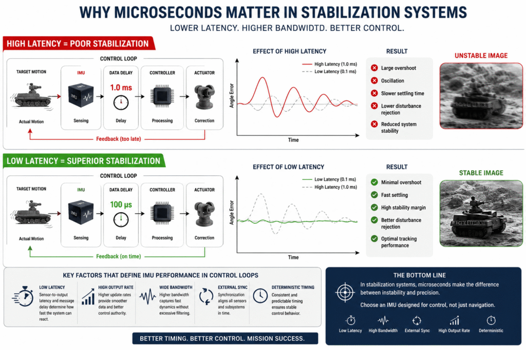
Figure 1 – Navigation Specifications Do Not Guarantee Stabilization Performance
This illustration highlights a common mistake in the IMU selection process: two sensors with similar datasheet specifications can deliver dramatically different stabilization performance. In EO/IR systems, gimbals, stabilized antennas, and unmanned platforms, even a few microseconds of additional latency can increase phase lag, reduce control-loop stability, and directly impact tracking accuracy and overall stabilization performance.
Why 1 Millisecond Is Not “Nothing”
Many engineers see:
Latency = 1 ms
and assume it is insignificant.
In a high-performance stabilization loop, it is not.
When a system performs hundreds or thousands of corrections per second, every microsecond contributes phase delay.
Every phase delay reduces control authority.
Every reduction in control authority impacts stabilization performance.
Eventually even an excellent IMU can produce disappointing system-level results:
- Less stable imagery
- Longer settling times
- Increased overshoot
- Higher controller workload
- Reduced disturbance rejection
The sensor itself may still be excellent.
The control loop performance is not.
This Is Where Datasheets Become Misleading
Most IMU comparisons focus on navigation-oriented specifications:
- Bias Stability
- ARW
- Drift
- Scale Factor Accuracy
These parameters are important.
But they do not fully predict stabilization performance.
For stabilization systems, different questions become critical:
- What is the true sensor-to-output latency?
- What is the message delay?
- What output rates are available?
- What bandwidth is available?
- Does the device support external synchronization?
- Is timing deterministic?
- How much latency do internal filters introduce?
These specifications rarely appear in the headline section of a datasheet.
Yet they often determine whether a stabilization project succeeds.
Two IMUs. Similar Specifications. Different Results.
In this project, both IMUs appeared remarkably similar on paper.
Both offered low noise.
Both were temperature calibrated.
Both met environmental requirements.
Both delivered impressive inertial specifications.
However, one sensor was architected specifically for high-performance control applications.
The difference was not the sensing element alone.
The difference was the complete timing architecture:
- Sampling strategy
- Processing pipeline
- Internal filtering
- Message delay
- External synchronization
- Deterministic timing behavior
And that difference changed the outcome.
Bandwidth: Lower Noise Does Not Always Mean Better Stabilization
One of the most common engineering mistakes is pursuing lower noise at any cost.
Reducing noise is relatively easy.
Apply more filtering.
The problem is that filtering introduces delay.
Delay introduces phase lag.
Phase lag degrades control performance.
As a result, an IMU with slightly higher noise but significantly higher bandwidth may outperform a quieter sensor in real-world stabilization applications.
This often surprises engineers accustomed to navigation-focused performance metrics.
Synchronization: The Problem Nobody Sees Until It Is Too Late
A modern EO/IR system typically includes:
- IMU
- Camera
- Encoders
- Motion Controller
- Mission Computer
Each subsystem operates according to its own clock.
Without synchronization, timing errors accumulate.
The camera sees the world at one instant.
The IMU measures motion at another.
The controller calculates corrections at a third.
Even if every subsystem is individually accurate, the overall system may be making decisions based on information that is no longer current.
For static systems, this may be tolerable.
For dynamic stabilization systems, it can be devastating.
Why Gladiator Technologies Takes A Different Approach
This is precisely why some inertial manufacturers focus on far more than sensor accuracy.
At Gladiator Technologies, the design philosophy centers around real-world stabilization and control performance.
Rather than optimizing solely for traditional navigation metrics, Gladiator places significant emphasis on:
- Ultra-low latency
- High bandwidth
- Deterministic timing
- External synchronization
- High-rate data output
- Fast processing architectures
The result is a family of inertial products specifically engineered for demanding control-loop applications.
For example, the LandMark™ 005 IMU offers:
- Up to 10 kHz output data rates
- Less than 115 µs message delay
- Up to 600 Hz bandwidth
- Up to 1000 Hz bandwidth in selected VELOX Plus configurations
- External synchronization capability up to 10 kHz
Similarly, the G300D and G300DH triaxial gyroscope families were designed around Gladiator’s VELOX processing architecture, delivering high-rate outputs, wide bandwidth, low latency, and synchronization features specifically valued in stabilization, tracking, and control applications.
These are not simply marketing specifications.
They are control-loop specifications.
Why This Matters In Defense Systems
Defense platforms rarely operate under ideal laboratory conditions.
They experience:
- Vehicle vibration
- Platform motion
- Mechanical shock
- Temperature extremes
- Dynamic target movement
- High optical magnification
Under these conditions, an IMU is not evaluated solely by its ability to measure motion.
It is evaluated by its ability to help the system react.
When stabilization performance becomes mission-critical, timing becomes a system-level design parameter.
Not merely a sensor parameter.
The Question Engineers Should Be Asking
The old question was:
What is the IMU’s bias stability?
The better question is:
How quickly, consistently, and synchronously can this IMU deliver usable information to my controller?
Or even more simply:
Was this IMU designed for navigation – or for stabilization?
Those are not the same requirement.
And they do not always lead to the same product choice.
Engineer’s Checklist Before Selecting An IMU For Stabilization
Before selecting an IMU for an EO/IR system, gimbal, stabilized antenna, UAV payload, or tracking platform, consider:
Latency
What is the actual sensor-to-output latency?
Message Delay
How quickly does data leave the device?
Output Rate
Can the output rate support the control loop?
Bandwidth
What bandwidth is available without excessive filtering?
External Synchronization
Can the IMU be synchronized with the rest of the system?
Timing Determinism
Are data updates predictable and consistent?
Internal Processing
What latency is introduced by internal filtering and processing?
Application Fit
Was the product designed for navigation – or for control?
Conclusion
The most important lesson from this project had nothing to do with ARW.
Nothing to do with bias stability.
Nothing to do with noise density.
The lesson was much simpler:
In stabilization systems, accurate information is not enough.
The information must arrive on time.
Two IMUs can appear nearly identical on a datasheet and still deliver dramatically different stabilization performance.
The difference may not be measured in degrees per hour.
It may be measured in microseconds.
And in modern EO/IR systems, gimbals, stabilized antennas, UAV payloads, and defense platforms, those microseconds can be the difference between acceptable performance and exceptional performance.
In stabilization systems, accuracy matters. But the time it takes information to reach the controller is often the difference between a good system – and an extraordinary one.