flagעברית
flagEnglish
3 Rabinovich St., Petah-Tikva, Israel
+972 3 9047744
office@amironic.co.il
Facebook
Twitter
LinkedIn
YouTube
  • Products
    • MEMS Inertial
      • Gyros & Accels
      • IMU
      • Inertial Navigation
      • AHRS
    • Circuit Breakers
      • Airpax Circuit Breakers
      • Electronic Circuit Breakers
      • Aircraft Circuit Breakers
      • Thermal Circuit Breakers
      • Sealing Solutions & Guards
    • Footswitches
      • Pedals & Bellows
      • USB
      • Air Switches
      • Medical
      • Modular Bases System
      • Industrial
      • Foot Potentiometers
      • Wireless
    • Mechanical & Transmisions
      • Gears
      • Sealing Solutions
      • Gearboxes
      • Couplings
      • Shafts & Bearings
      • Fasteners
      • Mechanical & Springs
      • Linear Motion
      • Anti-Vibration
    • Sensors
      • Thermostats
      • Temperature
      • Position
      • Pressure
      • Speed
      • Level Sensor
      • Load Cells
      • Flex Sensors
      • Membrane Potentiometer
    • Motors
      • Geared DC
      • Brushless DC
      • Step Motors with Gearbox
      • Torque Motors & Brushless Servo
      • DC Motors
    • Electronics
      • Xenon & IR Lamps
      • Counters & Meters
      • Microelectronics Packaging
      • Waterproof Switches
      • Micro Switches
    • Hand Control
      • Operator Controls (JOYSTICK)
      • Electrical
      • Pneumatic (Medical)
      • USB Hand Control
      • Air Push Button
      • Pressure Switch
      • IR Switch
    • Power Solutions
      • Rugged & Military Power Supply
      • Input Power Protection
      • Sealed Military Power Adaptor
      • Triple Output Military Power Supply Series – up to 250 W
    • Materials
      • Molybdenum and Advanced Alloys (TZM, MOLA, HCT)
      • Tungsten (Wolfram) and Advanced Alloys – High-Performance Materials for Extreme Conditions
      • Materials for Gears
  • Shop
  • Companies
  • About Amironic
  • News
  • Contact
Product was added to your cart

Cart

waze

How to Calculate Gear Ratio and Choose the Right Gears

Mechanics20/07/2026amironicLTD

How to Calculate Gear Ratio and Choose the Right Gears

Gears are among the most important components in mechanical power transmission systems. They are used to transfer motion and torque in a wide range of applications, from industrial machinery and robotics to medical equipment, aerospace systems, vehicles, and precision mechanisms.

One of the key parameters in designing a gear-driven system is the gear ratio. The gear ratio determines how rotational speed and torque change between the driving shaft and the driven shaft, directly affecting the overall performance of the system.

However, calculating the gear ratio is only one part of the design process. Selecting the appropriate gear type, material, heat treatment, manufacturing accuracy, and operating conditions is equally important, as these factors significantly influence system reliability, efficiency, and service life.

In this guide, you will learn how to calculate gear ratio, understand its effect on speed, torque, and power, explore the most common types of gears, examine the influence of gear materials and case hardening, and discover common design mistakes to avoid when developing mechanical power transmission systems.


How Is Gear Ratio Calculated?

The gear ratio is one of the most fundamental parameters in mechanical power transmission design. It determines how rotational speed changes between the driving gear and the driven gear, as well as how the available output torque is affected.

Although the calculation itself is straightforward, gear ratio has a significant impact on the performance of machines, robots, conveyors, gearboxes, automation systems, and precision mechanisms.

How to Calculate Gear Ratio

When two gears mesh together, the gear ratio is determined by the relationship between the number of teeth on the driven gear and the number of teeth on the driving gear.

The formula is:

Gear Ratio = Number of Teeth on the Driven Gear ÷ Number of Teeth on the Driving Gear

Example

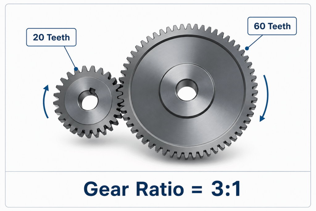
Assume the driving gear has 20 teeth and the driven gear has 60 teeth.

The gear ratio is:

60 ÷ 20 = 3

Therefore:

3:1

This means that for every three revolutions of the driving gear, the driven gear completes one full revolution.
How Does Gear Ratio Affect Rotational Speed?

One of the most important characteristics of a gear system is the direct relationship between gear ratio and the rotational speed of the driven shaft.

As the gear ratio increases, the driven gear completes fewer revolutions for the same amount of rotation produced by the driving gear. As a result, the output rotational speed decreases.

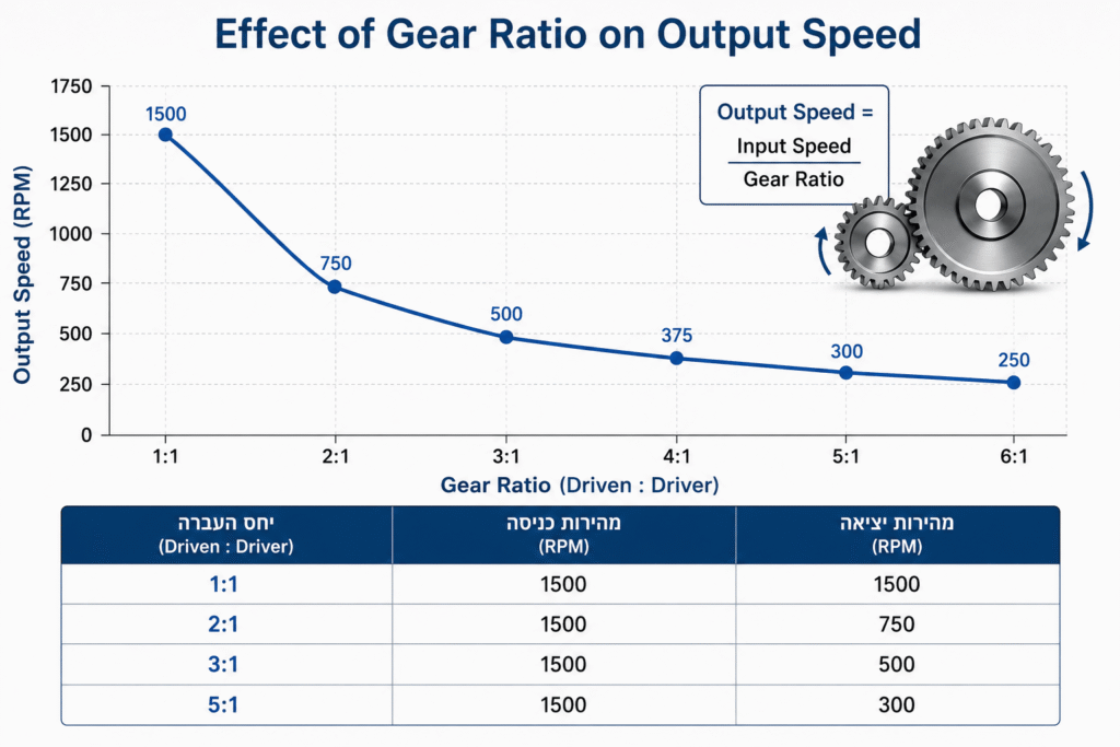
For example, if a motor rotates at 1,500 RPM and is connected to a pair of gears with a 3:1 gear ratio, the driven shaft will rotate at only 500 RPM.

The relationship is described by the following formula:

Output Speed = Input Speed ÷ Gear Ratio

Example

Gear Ratio Input Speed Output Speed
1:1 1,500 RPM 1,500 RPM
2:1 1,500 RPM 750 RPM
3:1 1,500 RPM 500 RPM
5:1 1,500 RPM 300 RPM

As shown in the table, increasing the gear ratio reduces the output speed in an inverse relationship. Doubling the gear ratio halves the output speed, while tripling the gear ratio reduces the output speed to one-third of the original value.

This principle is widely used in applications ranging from industrial gearboxes and conveyor systems to robotics, automation equipment, and precision motion control systems, where reducing rotational speed provides greater control, improved positioning accuracy, and increased output torque.

Figure 2. Effect of gear ratio on output speed. As the gear ratio increases, the rotational speed of the driven shaft decreases in an inverse relationship. In this example, the input speed is fixed at 1,500 RPM, while the gear ratio varies from 1:1 to 5:1.

How Does Gear Ratio Affect Torque?

One of the primary advantages of a gear system is its ability to convert speed into torque. As the gear ratio increases, the rotational speed of the driven shaft decreases, while the available output torque increases.

In an ideal system with no frictional losses, torque increases by the same factor that rotational speed decreases. Therefore, if the gear ratio is doubled, the output torque also doubles.

The output torque can be calculated using the following formula:

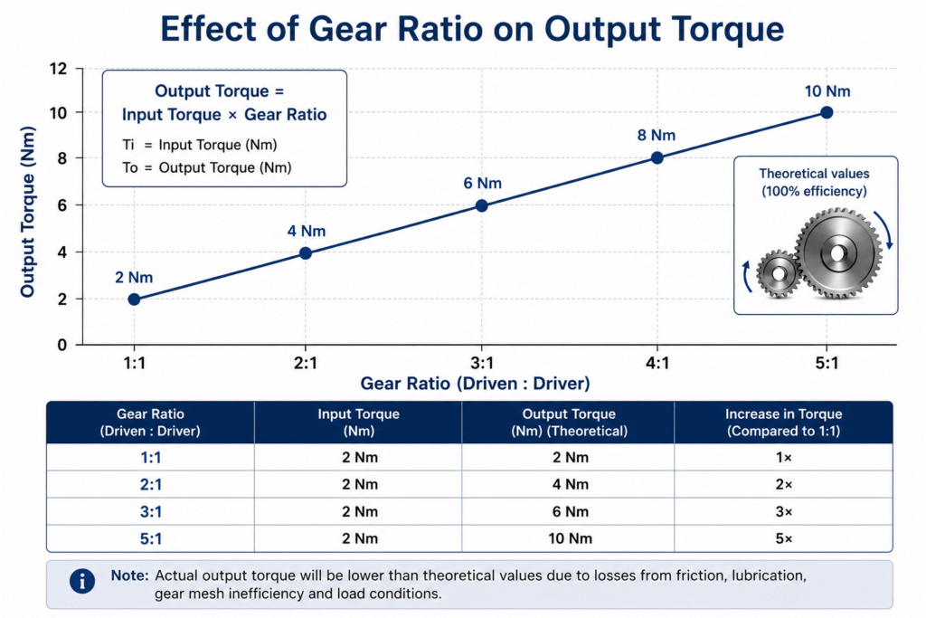
Output Torque = Input Torque × Gear Ratio

Example

If a motor delivers 2 Nm of input torque and is connected to a gear set with a 3:1 gear ratio, the output torque is:

2 × 3 = 6 Nm

In real-world applications, however, gear systems are not perfectly efficient. Friction, lubrication, manufacturing tolerances, bearing losses, and operating load all reduce efficiency, meaning the actual output torque will be slightly lower than the theoretical value.

The following table illustrates how output torque changes for a motor with a constant 2 Nm input torque.

Gear Ratio Input Torque Theoretical Output Torque
1:1 2 Nm 2 Nm
2:1 2 Nm 4 Nm
3:1 2 Nm 6 Nm
5:1 2 Nm 10 Nm

As the table shows, increasing the gear ratio also increases the torque available at the driven shaft. This is why gearboxes are widely used to reduce rotational speed while multiplying torque, particularly in applications that require moving heavy loads or overcoming high mechanical resistance.

Figure 3. Effect of gear ratio on output torque. As the gear ratio increases, the torque available at the driven shaft increases, while the rotational speed decreases. The values shown in the graph are theoretical, assuming 100% transmission efficiency and no frictional losses.

Does Gear Ratio Increase Power?

The short answer is no.

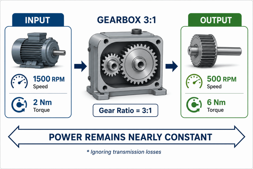
A gear ratio can reduce rotational speed and increase torque, but it does not create energy. Therefore, in an ideal system with no losses, the power remains constant.

The relationship between power, torque, and rotational speed is described by the following equation:

Power = Torque × Angular Velocity

As rotational speed decreases, torque increases by the same factor, resulting in essentially the same power output.

For example, a motor producing 2 Nm of torque at 1,500 RPM delivers approximately the same power after passing through a 3:1 gearbox. In this case, the output speed decreases to 500 RPM, while the output torque increases to approximately 6 Nm.

In real-world gear systems, however, energy losses occur due to gear tooth friction, lubrication, bearing friction, manufacturing tolerances, and other mechanical inefficiencies. As a result, the output power is always slightly lower than the input power.

The following table illustrates this relationship:

Gear Ratio Output Speed Output Torque Power (Ideal)
1:1 1,500 RPM 2 Nm Constant
2:1 750 RPM 4 Nm Constant
3:1 500 RPM 6 Nm Constant
5:1 300 RPM 10 Nm Constant

In other words, a gearbox does not make a motor more powerful. It simply trades rotational speed for torque according to the selected gear ratio.

Figure 4. Effect of gear ratio on speed, torque, and power. A 3:1 gearbox reduces the rotational speed from 1,500 RPM to 500 RPM while increasing the output torque from 2 Nm to 6 Nm. In an ideal system, the power remains essentially constant. In practice, however, small power losses occur due to friction, lubrication, and transmission efficiency.

How to Choose the Right Gear Ratio

Selecting the appropriate gear ratio is one of the most important decisions in designing a mechanical power transmission system. An incorrect gear ratio can result in insufficient output speed, inadequate torque, or unnecessary stress on both the motor and the gearbox.

For this reason, the design process should begin with the application requirements, not with the physical dimensions of the gears.

Engineers typically start by answering four key questions:

  • What output speed is required?
  • How much output torque is needed to drive the load?
  • What motor speed is available?
  • Are there any space or size constraints?

Once these parameters are defined, the required gear ratio can be calculated, allowing the selection of the gear set that best meets the desired performance.

Example 1 – Industrial Conveyor

An electric motor rotates at 1,500 RPM, while the conveyor must operate at only 300 RPM.

The required gear ratio is:

1,500 ÷ 300 = 5

Therefore, a 5:1 gear ratio should be selected.

In addition to reducing the output speed, the output torque will increase by approximately five times (assuming an ideal, loss-free system).

Example 2 – Industrial Robot

A robotic joint requires high positioning accuracy and smooth motion. In such applications, a relatively high gear ratio is often selected to increase motion resolution, improve control, and reduce the load seen by the motor.

However, an excessively high gear ratio can reduce the system’s dynamic response. The optimal design therefore requires balancing precision, speed, and torque.

Example 3 – Precision Positioning System

Precision positioning systems, such as XY tables, optical instruments, and medical equipment, often use higher gear ratios to achieve finer motion control and improved positioning accuracy.

In these applications, engineers must also consider backlash, transmission stiffness, and gear manufacturing accuracy, as all of these factors directly affect positioning precision and overall system performance.

General Guidelines for Selecting a Gear Ratio

Application Typical Gear Ratio
Motion transmission without speed reduction 1:1
Moderate torque multiplication 2:1 to 4:1
Industrial conveyors and machinery 4:1 to 10:1
Robotics and automation 5:1 to 30:1
Servo systems and precision positioning 10:1 to 100:1
Multi-stage gearboxes Above 100:1

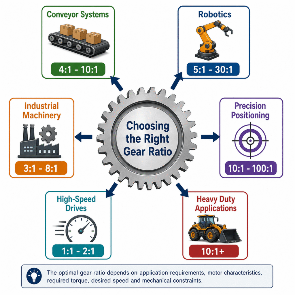
It is important to note that the values shown in the table are general guidelines only. The optimal gear ratio depends on the application’s specific requirements, including motor characteristics, required output torque, desired speed, available installation space, and other mechanical constraints.

Figure 5. Typical gear ratios for different applications. Each application has unique requirements for speed, torque, precision, and dynamic performance, so there is no single gear ratio that is suitable for every system. The values shown in this figure represent commonly used industry ranges and serve as a practical starting point for selecting an appropriate gear transmission.

How Does Gear Material Affect Torque Transmission?

While the gear ratio determines the relationship between rotational speed and torque, it is not the only factor that affects gearbox performance. The material from which a gear is manufactured also has a significant impact on the amount of torque it can transmit, its durability, and the overall service life of the transmission.

In general, the stronger and stiffer the gear material, the greater the torque that can be transmitted using the same gear geometry and module. Plastic materials, on the other hand, offer advantages such as lower weight, quieter operation, and excellent corrosion resistance, but they are typically suitable for lower torque applications.

For example:

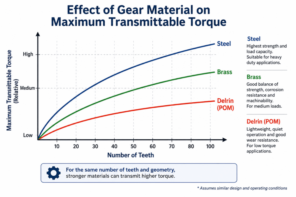
  • Steel – Ideal for transmitting high torque and handling heavy loads. Widely used in industrial gearboxes, heavy machinery, and high-power drive systems.
  • Brass – Provides a good balance of strength, corrosion resistance, and machinability. Commonly used in medium-load applications where low friction and good wear characteristics are important.
  • Delrin (Acetal/POM) – A lightweight engineering plastic frequently used in light-duty mechanisms, robotics, medical devices, and precision instruments. It offers quiet operation, low weight, and in some applications can operate without lubrication, but it is intended for relatively low torque loads.

It is important to remember that material selection should not be based on torque alone. Engineers must also consider rotational speed, operating temperature, noise requirements, environmental conditions, lubrication requirements, wear resistance, and the desired service life of the transmission.

Figure 6. Effect of gear material on torque transmission capability. For the same number of teeth and identical gear geometry, materials with higher mechanical strength can transmit greater torque. Steel is best suited for heavy-duty, high-load applications, brass provides a balance between strength and corrosion resistance, and Delrin (POM) is primarily intended for light-duty applications where low weight, quiet operation, and excellent wear resistance are important.

Why Are Case-Hardened Gears Used?

Many power transmission systems require gears to operate under high loads for millions of operating cycles. To combine excellent wear resistance with high mechanical strength and impact resistance, engineers often use case-hardened gears.

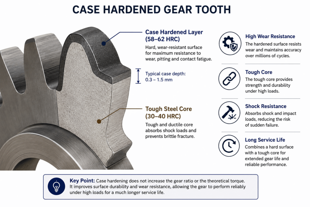
In the case hardening process, only the outer surface of each gear tooth is hardened, while the core of the material remains tough and retains enough ductility to absorb shock loads.

This combination provides significant advantages over gears made from the same material without heat treatment.

Benefits of Case Hardening

  • Significantly improved wear resistance.
  • Increased resistance to contact fatigue.
  • Reduced risk of pitting on the tooth surface.
  • Longer service life under millions of load cycles.
  • A tough core that absorbs impact loads and reduces the risk of sudden tooth fracture.

When Should Case-Hardened Gears Be Used?

Case-hardened gears are commonly found in applications such as:

  • Industrial gearboxes
  • High-duty-cycle servo systems
  • Robotics and industrial automation
  • Mining and heavy equipment
  • Aerospace and defense systems
  • Automotive and off-highway power transmission systems

Does Case Hardening Increase the Maximum Torque Capacity?

Not necessarily.

The torque capacity of a gear is determined primarily by factors such as gear size, number of teeth, module, face width, material properties, and the overall gear design.

Case hardening does not change the gear ratio, nor does it directly increase the amount of torque a gear can transmit. Instead, its primary benefit is maintaining gear performance over time by reducing wear, improving fatigue resistance, and extending the service life of the transmission under high loads and repeated operating cycles.

Figure 7. Cross-sectional view of a case-hardened gear. During the case-hardening process, an extremely hard outer layer is formed, providing excellent resistance to wear, pitting, and contact fatigue, while the steel core remains tough and relatively ductile to absorb shock loads and reduce the risk of brittle fracture. This combination delivers long service life and high reliability in power transmission systems operating under heavy loads and high-duty-cycle conditions.

Summary

Selecting the right gears involves much more than simply calculating the gear ratio. A successful gear design must also consider rotational speed, torque, material selection, heat treatment, manufacturing accuracy, lubrication, and operating conditions. Properly balancing all of these factors results in a transmission system that is reliable, efficient, and capable of delivering a long service life.

Whether you are designing a robotic system, an industrial gearbox, or a precision motion mechanism, understanding the principles presented in this guide will help you select the most suitable gear solution for your application.

Common Mistakes When Selecting Gears and Gear Ratios

Even when the gear ratio is calculated correctly, poor gear selection can lead to excessive wear, increased noise, premature failure, or even complete system breakdown. Below are some of the most common mistakes engineers should avoid.

1. Choosing a Gear Ratio Based Only on Speed

Many engineers focus exclusively on achieving the desired output speed while overlooking the required output torque. As a result, the motor may be unable to drive the load, even though the rotational speed appears to be correct.

2. Using Gears That Are Too Small

Gears with a very low tooth count may suffer from less efficient tooth engagement, increased noise, and accelerated wear. In some cases, undercutting can occur, significantly reducing tooth strength.

3. Ignoring Material Selection

Choosing an inappropriate gear material can dramatically shorten the life of the transmission. For example, plastic gears are well suited for lightweight, quiet-running applications but are not intended to carry the heavy loads that hardened steel gears can withstand.

4. Not Using Case-Hardened Gears When Required

In applications involving high loads or long duty cycles, using gears without appropriate heat treatment can result in accelerated wear, pitting, and material fatigue.

5. Neglecting Lubrication

Even the highest-quality gears cannot perform properly without adequate lubrication. Insufficient lubrication—or the use of an unsuitable lubricant—increases friction, raises operating temperatures, and significantly reduces gearbox life.

6. Overlooking Manufacturing Accuracy

Poor shaft alignment, incorrect center distance, or low manufacturing precision can cause excessive noise, vibration, uneven load distribution, and premature gear wear.

7. Failing to Include a Safety Factor

Designing a gearbox based only on nominal operating loads ignores shock loads, frequent starts and stops, and changing operating conditions. A suitable safety factor should always be included to ensure reliable long-term operation.

Further Reading

For a broader understanding of motion transfer system design and the role of gears and couplings in overall system behavior, the following articles provide additional engineering insights:

  • Gears & Couplings: An Engineering Guide to Precision Motion Transfer

  • How to Choose the Right Coupling Without Guessing

  • Common Coupling Failures and How to Prevent Them

  • Gear Material Selection Guide: Strength, Wear, Corrosion & Environment – How to Choose Correctly

  • Backlash Is Not a Number: Understanding What Really Determines Accuracy, Stability, and System Life

  • Spur, Helical and Worm Gears – Engineering Differences and How to Choose the Right One

  • Backlash in Gears – From Geometry to System Behavior: Understanding what really happens between gear teeth
  • Small Spur Gears: Why Miniaturization Creates Hidden Mechanical Problems
  • Gear Hardening Explained – Why Case Hardened Gears Dominate Heavy Duty Power Transmission
  • Why a Million-Dollar Medical System Still Uses Rack & Pinion
  • Why Most Engineers Use Bevel Gears for Only 10% of What They Can Actually Do
  • Why the Number of Starts in a Worm Gear Matters More Than the Gear Ratio
  • The Gearbox Isn’t the Problem – It’s Simply the First to Pay for Design Mistakes
  • When the System Starts to Vibrate – Don’t Rush to Retune the Motion Controller

Frequently Asked Questions (FAQ)

Which Type of Gear Is Best for My Application?

The best gear type depends on several factors, including the required gear ratio, torque, rotational speed, shaft orientation, positioning accuracy, and acceptable noise level. Depending on the application, engineers may choose from spur gears, helical gears, bevel gears, worm gears, internal gears, and other specialized gear types.

When Should I Choose Helical Gears?

Helical gears are ideal when quiet operation, smooth power transmission, and higher load capacity are required. They are widely used in industrial machinery, gearboxes, robotics, and automation systems.

When Are Bevel Gears Used?

Bevel gears are used to transmit motion between intersecting shafts, most commonly at a 90-degree angle. They are commonly found in power transmission systems, robotics, industrial equipment, and specialized machinery.

When Should Anti-Backlash Gears Be Used?

Anti-backlash gears are recommended whenever extremely high positioning accuracy is required and gear play must be minimized. Typical applications include CNC machines, robotics, medical devices, optical systems, and precision measuring equipment.

When Should Worm Gears Be Selected?

Worm gears are an excellent choice when a high gear ratio is required in a compact package, when high output torque is needed, or when self-locking characteristics are desirable, depending on the gear geometry and operating conditions.

How Do I Select a Timing Belt and Pulleys?

Timing belt selection depends on factors such as transmitted power, torque, rotational speed, center distance, belt width, and required service life. An incorrect selection can result in tooth skipping, accelerated wear, and premature system failure.

When Is a Rack and Pinion System the Better Choice?

A rack and pinion mechanism is used when rotational motion must be converted into precise linear motion. It is widely used in CNC machines, robotics, automated gates, and precision positioning systems.

What Is Backlash, and When Does It Become a Problem?

Backlash is the small clearance between mating gear teeth. A certain amount of backlash is necessary to accommodate lubrication and thermal expansion. However, in high-precision applications such as servo systems and robotics, excessive backlash reduces positioning accuracy. In these cases, anti-backlash gears or anti-backlash worm gear systems are often preferred.

Can Gears Be Manufactured to Custom Specifications?

Yes. In many cases, gears can be manufactured to customer specifications, including the number of teeth, module, material, heat treatment, accuracy grade, face width, bore size, keyway, and special surface coatings.

How Do I Choose the Right Gear Material?

Material selection depends on the required torque, rotational speed, operating environment, and desired service life. Steel is suitable for high-load applications, case-hardened steel provides superior wear resistance, brass offers excellent corrosion resistance and machinability, while Delrin (POM) is commonly used for lightweight, quiet-running mechanisms.

Can I Source an Entire Power Transmission System from a Single Supplier?

Yes. In many cases, a single supplier can provide a complete mechanical power transmission solution, including gears, timing pulleys and belts, rack and pinion systems, shafts, bearings, couplings, gearboxes, and other drivetrain components. Sourcing these components together can simplify both the engineering design process and procurement.

Glossary

Backlash

The small clearance between the teeth of two meshing gears. A certain amount of backlash is necessary to allow for lubrication and thermal expansion, but excessive backlash can reduce positioning accuracy and overall system performance.

Bevel Gear

A gear used to transmit motion between two intersecting shafts, most commonly at a 90-degree angle.

Bore

The central hole of a gear, used to mount it onto a shaft.

Case Hardening

A heat treatment process in which only the outer surface of the gear teeth is hardened while the core remains tough and relatively ductile. This improves wear resistance, contact fatigue strength, and overall service life.

Gear Ratio

The ratio between the number of teeth on the driven gear and the number of teeth on the driving gear. The gear ratio determines the relationship between output speed and torque.

Helical Gear

A gear with angled teeth that provides smoother, quieter operation and a higher load-carrying capacity than a spur gear.

Idler Gear

An intermediate gear placed between two other gears to change the direction of rotation without altering the gear ratio.

Internal Gear

A gear whose teeth are located on the inside diameter. Internal gears are commonly used in planetary gear systems and compact gearboxes.

Keyway

A machined slot in both the shaft and the gear bore that accommodates a mechanical key, allowing torque to be transmitted securely between the shaft and the gear.

Module

One of the most important gear parameters. The module defines the size of the gear teeth and must be identical for two gears to mesh correctly.

Pitch Circle Diameter (PCD)

The theoretical diameter at which two gears mesh. Most gear design calculations are based on the pitch circle diameter.

Pressure Angle

The angle at which force is transmitted between mating gear teeth. The most common standard pressure angles are 20° and 14.5°.

Rack

A straight gear used to convert rotational motion into linear motion, typically as part of a rack-and-pinion system.

Spur Gear

The most common type of gear, featuring straight teeth that are parallel to the axis of rotation.

Tooth Profile

The geometric shape of a gear tooth. Most gears use an involute tooth profile, which provides smooth meshing, constant velocity ratio, and efficient power transmission.

Worm Gear

A gear set consisting of a worm and a worm wheel, capable of achieving very high gear reduction ratios in a compact design. Depending on the geometry, worm gears may also provide self-locking characteristics.

Pinion

The smaller gear in a gear pair, typically serving as the driving gear.

Tags: Amironic

Related Articles

Why a Million-Dollar Medical System Still Uses Rack & Pinion

03/06/2026amironicLTD

The Silent Problem of Precision Systems – Why Gyros and IMUs Are Control Components, Not Just Sensors

01/02/2026amironicLTD

When the System Starts to Vibrate – Don’t Rush to Retune the Motion Controller

14/07/2026amironicLTD

Recent Posts

  • How to Calculate Gear Ratio and Choose the Right Gears
  • How Does an INS Algorithm Really Work?
  • Your Pressure Sensor May Be Accurate. Your Measurement May Not Be – Why a ±0.5% Accuracy Specification Doesn’t Guarantee a ±0.5% Measurement
  • From IMU to INS: How a Tactical Navigation System Is Really Built
  • What Can We Learn from 40-Year-Old Hydraulic-Magnetic Circuit Breakers Still in Service?

Categories

  • Air Switch
  • Circuit Breakers
  • Elapsed Time Indicator
  • Feedthrough
  • Footswitches
  • Gears & Transmission
  • Hour Meters
  • Infra Red Switches
  • INFRARED LAMPS
  • Low Noise Inertial MEMS
  • Mechanics
  • MEMS Gyroscope
  • MEMS Inertial
  • Microelectronics
  • Motors
  • Position Sensors
  • Power Supply
  • Pressure Sensors
  • Pressure Switch
  • Temperature Sensors
  • Tungsten and Molybdenum
  • Uncategorized
  • Vacuum Switches

Quick Contact

Fill out the form and our representatives will return to you

    Name (required)

    Email (required)

    Phone

    Message

    This site is protected by reCAPTCHA and the Google
    Privacy Policy and
    Terms of Service apply.

    Amironic Ltd.

    3 Rabinovich Street, Petah Tikva 4928144 , Israel. Tel: +972-3-9047744 E-mail: office@amironic.co.il
    Email
    Facebook
    Twitter
    LinkedIn
    YouTube
    Press on the ISO Certificate below for download
    ISO 9001:2015 Certification
    • MEMS Inertial
    • Circuit Breakers
    • Footswitches
    • Mechanical & Transmisions
    • Sensors
    • Motors
    • Electronics
    • Hand Control
    • Power Solutions

    News

    • How to Calculate Gear Ratio and Choose the Right Gears
    • How Does an INS Algorithm Really Work?
    • Your Pressure Sensor May Be Accurate. Your Measurement May Not Be – Why a ±0.5% Accuracy Specification Doesn’t Guarantee a ±0.5% Measurement
    • From IMU to INS: How a Tactical Navigation System Is Really Built
    • What Can We Learn from 40-Year-Old Hydraulic-Magnetic Circuit Breakers Still in Service?
    About AmironicContactעברית
    © 2022 Amironic All rights reserved. All Trademarks are the property of their respective owners.
    • Increase Font
    • Decrease Font
    • Black & White
    • Inverse Colors
    • Highlight Links
    • Regular Font
    • Reset