flagעברית
flagEnglish
3 Rabinovich St., Petah-Tikva, Israel
+972 3 9047744
office@amironic.co.il
Facebook
Twitter
LinkedIn
YouTube
  • Products
    • MEMS Inertial
      • Gyros & Accels
      • IMU
      • Inertial Navigation
      • AHRS
    • Circuit Breakers
      • Airpax Circuit Breakers
      • Electronic Circuit Breakers
      • Aircraft Circuit Breakers
      • Thermal Circuit Breakers
      • Sealing Solutions & Guards
    • Footswitches
      • Pedals & Bellows
      • USB
      • Air Switches
      • Medical
      • Modular Bases System
      • Industrial
      • Foot Potentiometers
      • Wireless
    • Mechanical & Transmisions
      • Gears
      • Sealing Solutions
      • Gearboxes
      • Couplings
      • Shafts & Bearings
      • Fasteners
      • Mechanical & Springs
      • Linear Motion
      • Anti-Vibration
    • Sensors
      • Thermostats
      • Temperature
      • Position
      • Pressure
      • Speed
      • Level Sensor
      • Load Cells
      • Flex Sensors
      • Membrane Potentiometer
    • Motors
      • Geared DC
      • Brushless DC
      • Step Motors with Gearbox
      • Torque Motors & Brushless Servo
      • DC Motors
    • Electronics
      • Xenon & IR Lamps
      • Counters & Meters
      • Microelectronics Packaging
      • Waterproof Switches
      • Micro Switches
    • Hand Control
      • Operator Controls (JOYSTICK)
      • Electrical
      • Pneumatic (Medical)
      • USB Hand Control
      • Air Push Button
      • Pressure Switch
      • IR Switch
    • Power Solutions
      • Rugged & Military Power Supply
      • Input Power Protection
      • Sealed Military Power Adaptor
      • Triple Output Military Power Supply Series – up to 250 W
    • Materials
      • Molybdenum and Advanced Alloys (TZM, MOLA, HCT)
      • Tungsten (Wolfram) and Advanced Alloys – High-Performance Materials for Extreme Conditions
      • Materials for Gears
  • Shop
  • Companies
  • About Amironic
  • News
  • Contact
Product was added to your cart

Cart

waze

High-Energy Laser Interception – The Engineering Behind Stable Line of Sight, Power Delivery, and Thermal Management

MEMS Inertial, Power Supply28/07/2026amironicLTD

High-Energy Laser Interception Is About More Than Laser Power

A high-energy laser interception system does not fail simply because the beam is too weak.

It can fail when the electrical power supply collapses at the exact moment engagement begins, when repeated engagements drive the system beyond its thermal operating envelope, or when minute vibrations disturb the line of sight, spreading the laser energy over an area too large to achieve the required energy density.

From an operational perspective, the mission appears straightforward:

Detect. Track. Lock. Fire. Neutralize.

From an engineering perspective, however, the system is fighting three simultaneous battles.

  • Power – Deliver high, stable electrical power without destabilizing the platform’s electrical network.
  • Thermal Management – Remove the heat that is not converted into laser energy while sustaining repeated engagements.
  • Line of Sight – Maintain precise beam pointing despite platform motion, vibration, structural dynamics, and system latency.

Although the laser beam reaches its target at the speed of light, the system responsible for generating, conditioning, cooling, and steering that beam operates under very real constraints of voltage, current, temperature, response time, and angular accuracy.

Consequently, the key operational question is not simply:

How many kilowatts can the laser produce?

Rather, it is:

How much energy can be concentrated on the same point of the target for the required duration, and how many engagements can be sustained before electrical or thermal limits are reached?

That distinction separates an impressive laboratory demonstration from an operational laser interception system capable of countering persistent threats.


A Laser Does Not Fire a Projectile – It Builds Damage

Unlike a missile, which carries its destructive energy to the target, a laser weapon must continuously deliver energy through the atmosphere.

Damage is rarely created the instant the beam reaches the target. Instead, it accumulates through a sequence of physical processes:

Optical Absorption → Local Heating → Material Degradation → Structural or Functional Failure

If the beam remains precisely focused, temperature rises rapidly at the point of impact. If the line of sight drifts or vibrates, the beam energy is distributed across multiple locations, reducing the energy deposited at any single point.

The same principle applies inside the laser weapon itself. Energy that is not converted into the outgoing laser beam does not disappear—it remains within the system as heat that must be removed.

This leads to the first fundamental engineering principle of high-energy laser interception:

Every laser engagement is simultaneously an optical event, an electrical event, and a thermal event.
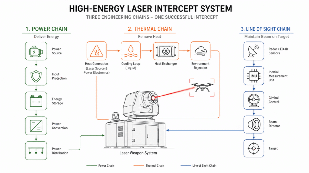
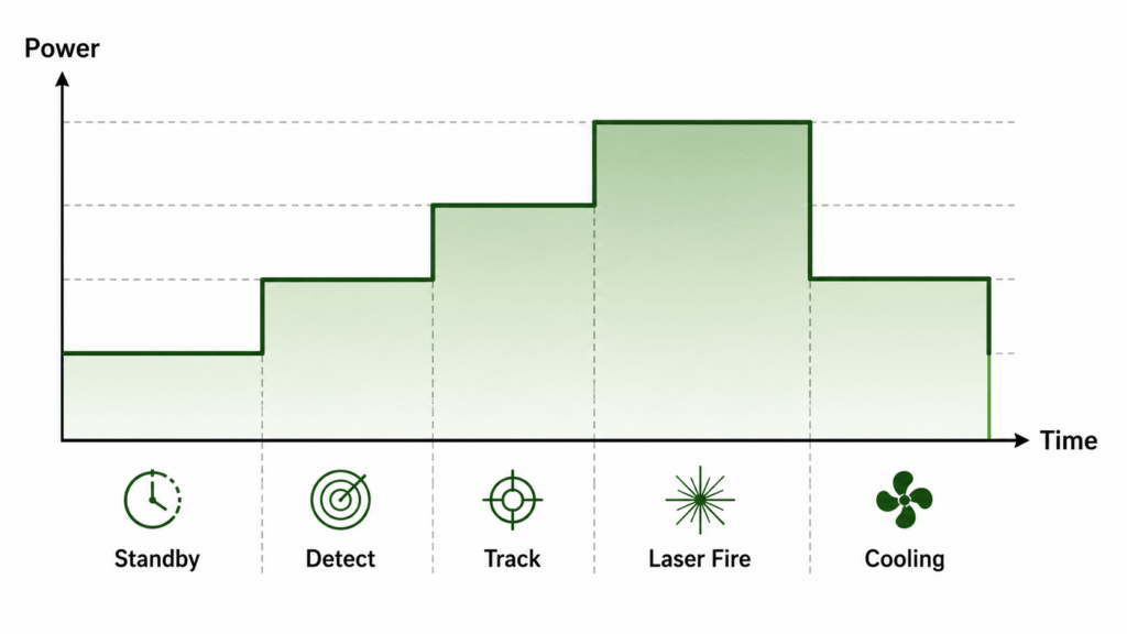
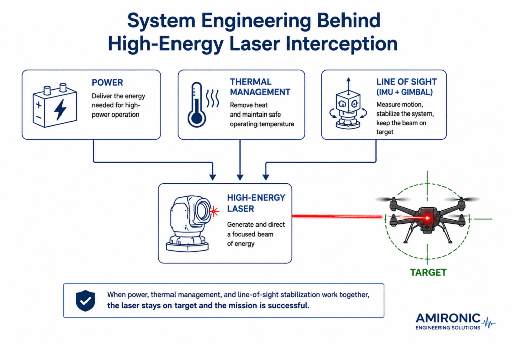
Figure 1. The success of a high-energy laser interception system is determined not only by laser output power, but also by its ability to deliver electrical power, dissipate heat, and maintain a stable line of sight throughout the engagement.

Power Delivery – The Laser Is Not the Largest Energy Consumer

When discussing a high-energy laser interception system, most attention is focused on the laser output itself – 50 kW, 100 kW, or even higher.

In reality, the laser beam is only one of many power consumers within the system.

During target detection, tracking, engagement, and interception, numerous subsystems operate simultaneously, including:

  • Radar and EO/IR sensors
  • Fire control computers
  • Gimbal actuators
  • The IMU
  • Cooling pumps
  • Heat exchangers
  • Power conversion electronics
  • The laser source

Each subsystem requires its own voltage level, current profile, power quality, and dynamic response.

In other words, a high-energy laser weapon is not powered by a single power supply—it relies on a complete power architecture.

That architecture must simultaneously distribute electrical energy to numerous subsystems while maintaining stable operation, even under rapidly changing load conditions.


The Challenge Begins the Moment the Trigger Is Pulled

The transition from standby to engagement places an immediate and significant demand on the electrical system.

Within milliseconds, multiple subsystems become active simultaneously:

  • The laser source
  • Cooling systems
  • Gimbal stabilization
  • Processing computers
  • Beam steering and guidance electronics

From the perspective of the power source, this represents a rapid and substantial load transient.

If the electrical architecture is not properly designed, several problems may occur:

  • Voltage Sag
  • High Inrush Current
  • Electromagnetic Interference (EMI)
  • Excessive heating of power converters
  • Reset or malfunction of sensitive electronics

Simply put,

the laser beam may never leave the system before the interception has already failed.


Power Architecture of a High-Energy Laser Weapon System

Generator / Battery
        │
        ▼
Input Protection
        │
        ▼
Power Conditioning
        │
        ▼
Energy Storage
        │
        ▼
DC Bus

Why Not Connect the Laser Directly to the Generator?

This is often the first question an engineer asks.

If the platform already has a generator capable of producing the required electrical power, why not connect the laser system directly to it?

The answer is that a laser interception system does not operate under a constant electrical load.

Throughout an engagement, the system continuously transitions through multiple operating states:

  • Standby
  • Target Detection
  • Target Tracking
  • Laser Preparation
  • Firing
  • Cooling
  • Transition to the Next Target

Each operating state places a different demand on the electrical system.

The laser source, cooling pumps, gimbal actuators, fire control computers, and sensors do not become active simultaneously, nor do they draw the same amount of current.

In practice, every subsystem has its own electrical profile, responding at different times and with different power requirements.

This creates one of the primary challenges of the system’s electrical architecture.


Electrical Current Does Not Change Smoothly

A common misconception is to imagine power consumption as a constant, steady load.

In reality, the electrical demand resembles a sequence of rapid step changes rather than a straight line.

As subsystems switch on and off, the electrical load can increase or decrease dramatically within milliseconds. These abrupt load transients can introduce voltage sag, current spikes, and power quality disturbances throughout the platform’s electrical network.

For this reason, the generator alone is typically insufficient to support a high-energy laser weapon. A complete power architecture-including energy storage, power conditioning, and power distribution-is required to absorb rapid load variations and provide stable electrical power to every subsystem throughout the engagement.

At every transition between operating states, the power system must respond almost instantaneously.

It cannot tolerate even a brief voltage sag or a delay of a few hundred milliseconds.

Even if the laser itself continues operating, another subsystem may lose synchronization, trigger a protection mechanism, or reset.

During an engagement, any of these events can result in the loss of the target.

Every Subsystem Has a Different Power Profile

Even when two subsystems consume similar amounts of power, their electrical behavior can be completely different.

For example:

Subsystem Typical Power Profile
Radar Nearly continuous
EO/IR Sensors Relatively stable
Mission Computer Varies with computational load
IMU Very low and highly stable
Gimbal Motors Highly dynamic
Cooling Pumps Varies with thermal load
Laser Source Highest instantaneous load

From the perspective of the power architecture, there is no single electrical load.

Instead, the system consists of multiple subsystems, each drawing energy at different times, with different current profiles and dynamic characteristics.

For this reason, the electrical architecture is designed to support the entire mission rather than the laser alone.


A Power System Must Anticipate the Load

A well-designed power system does more than react to changing loads.

It anticipates them.

Before a laser firing sequence begins, the control system may already activate the cooling pumps, stabilize the DC bus, and verify that sufficient stored energy is available for every critical subsystem.

In other words, electrical power is not simply delivered to the system.

It is actively managed.

This is why advanced laser weapon systems typically incorporate components such as:

  • Input Power Protection
  • Power Conditioning
  • DC/DC Converters
  • Energy Storage
  • Power Distribution Units
  • Electronic Circuit Protection

Each addresses a different challenge within the power chain.


Why Not Simply Install a Larger Generator?

At first glance, the answer appears obvious.

If the laser requires hundreds of kilowatts during firing, why not install a larger generator?

In practice, generation capacity is not the primary challenge.

The real challenge is how quickly that power can be delivered.

Generators, diesel engines, and even batteries do not respond well to sudden load transients.

When the laser demands a rapid increase in power, the energy source cannot always respond immediately.

This is precisely why advanced laser systems rarely connect the laser source directly to the primary energy source.

Instead, a dedicated power management layer sits between them.


Energy Storage – The Shock Absorber of the Electrical System

The power architecture can be compared to a water distribution system.

The generator acts as the pump.

The laser acts as a high-pressure fire hose.

When the hose is opened suddenly, the pump alone cannot instantly supply the required flow.

A storage tank is therefore added to absorb the transient demand.

In a high-energy laser system, that storage element may consist of:

  • Battery Banks
  • Supercapacitors
  • DC Bus Capacitors
  • Hybrid Energy Storage Systems

During standby operation, the primary energy source charges the storage system.

When firing begins, the stored energy supplies the immediate power demand.

After the engagement, the primary energy source replenishes the energy reserve.

In simple terms:

The generator supports the mission. The energy storage system supports the shot.

This distinction is fundamental to the design of modern high-energy laser systems.


Not Every Kilowatt Reaches the Target

One of the most common misconceptions is that a 100 kW laser converts all of its electrical input into laser output.

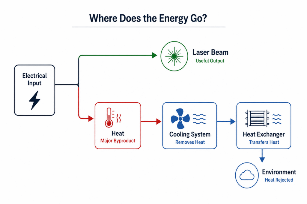
In reality, a significant portion of the electrical energy becomes heat.

The laser source, power electronics, voltage converters, and supporting subsystems all generate thermal energy that must be removed.

As laser output power increases, so does the thermal load imposed on the cooling system.

In other words,

the more powerful the laser beam, the more capable the cooling system must become.

This is why high-energy laser systems typically incorporate dedicated cooling loops, heat exchangers, pumps, and high-capacity thermal management hardware.

As laser output continues to increase, thermal management becomes one of the primary engineering drivers of the entire system architecture.


The First Engineering Paradox

Most people assume that the primary challenge is generating a laser beam capable of delivering hundreds of kilowatts.

Systems engineers recognize a different challenge:

What happens to all the energy that does not become laser light?

At that point, the problem is no longer one of optics.

It becomes a problem of thermodynamics.

And from that moment onward, thermal management becomes an integral part of the power architecture rather than a separate supporting subsystem.

Figure 3. Electrical input energy in a high-energy laser system is distributed between optical output and thermal losses generated by the laser source and power electronics. Effective thermal management is critical for sustaining repeated engagements and preserving system performance over time.

Thermal Management – The True Challenge of High-Energy Laser Systems

It is easy to think of a laser system as “wasting” energy.

In reality, no energy simply disappears.

Every watt that is not converted into laser light remains inside the system.

It heats:

  • The laser source
  • Power converters
  • Switching electronics
  • Cables and connectors
  • Cooling pumps
  • The mechanical structure supporting the system

In other words, every successful engagement adds more heat to the platform.

And that heat continues to accumulate long after the laser beam has been switched off.


The Real Challenge Begins with the Second Engagement

A successful laboratory demonstration is one thing.

An operational weapon system is judged by an entirely different standard.

It must remain effective when facing:

  • Multiple unmanned aerial systems
  • Rocket salvos
  • Successive targets arriving with little or no recovery time

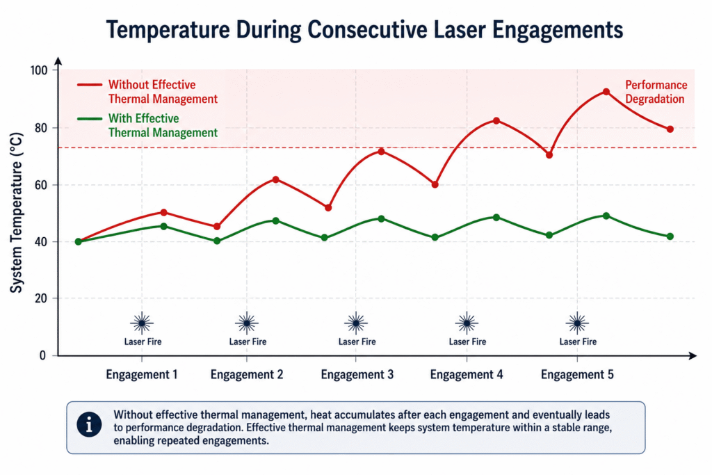
Under these conditions, the laser system has little opportunity to cool between engagements.

Each firing cycle begins at a higher temperature than the previous one.

At some point, the engineering challenge is no longer whether the laser can generate sufficient optical power.

The question becomes:

Can it continue to deliver the same beam quality after repeated engagement cycles?

This is no longer a power generation problem.

It is a thermal energy management problem.


Heat Affects More Than Reliability

When people think about overheating, they often imagine electronic components failing.

In reality, long before permanent damage occurs, temperature begins to change the behavior of the entire system.

Metals expand.

Optical lenses shift slightly.

Mirrors experience microscopic deformation.

Mechanical structures change their geometry by only a few micrometers.

In a high-precision optical system, even changes of this magnitude can affect beam quality and reduce the system’s ability to keep the laser focused on the same point of the target.

In other words,

heat is not only a reliability issue.

It is also a precision issue.


Cooling Is Not About Removing the Maximum Amount of Heat

This leads to one of the most important principles in the design of precision optical systems.

The intuitive assumption is simple:

The colder the system, the better.

In practice, that is not always true.

In laser systems, as well as electro-optical payloads, telescopes, thermal imaging systems, and inertial navigation units, the primary challenge is often not the absolute temperature.

It is the temperature distribution throughout the system.

When one side of the structure heats more rapidly than another, thermal gradients develop.

These gradients produce uneven material expansion, mechanical stress, and subtle structural distortion.

Although these effects are often measured in micrometers, they can significantly influence optical alignment and pointing accuracy.

For this reason, the objective is not always to cool individual components as much as possible.

Instead, engineers often seek to maintain a stable and uniform thermal field across the entire system.

This is why some advanced systems deliberately incorporate controlled heaters.

Their purpose is not to increase temperature, but to minimize thermal gradients and preserve mechanical and optical stability during operation.

In other words,

A thermally stable system is often more valuable than a colder system with non-uniform temperature distribution.

Figure 4. A successful single-shot engagement is not sufficient to demonstrate operational performance. High-energy laser systems must maintain thermal stability throughout repeated engagements to ensure consistent beam power, beam quality, and pointing accuracy over the duration of the mission.

Systems Engineers Do Not Simply Need More Power – They Need Stable Power

By now, it should be clear that a high-energy laser weapon requires far more than a high-capacity energy source.

It requires a complete power architecture capable of handling dynamic loads, electrical disturbances, and harsh operating environments without compromising mission continuity.

In military platforms, the electrical architecture typically consists of several coordinated layers, each addressing a different engineering challenge.

Engineering Challenge Typical Solution
Voltage transients and Load Dump MIL-STD-1275F Input Protection
Electromagnetic interference EMI/EMC Filters
Multiple operating voltages Rugged DC/DC Converters
Peak power during laser firing Energy Storage Modules
Power distribution across subsystems Power Distribution Units (PDUs)
Circuit protection Electronic Circuit Protection

Each of these technologies addresses a different point within the electrical power chain.

Only their combined operation allows the system to remain stable while power demands change rapidly throughout the mission.


Amironic’s Engineering Expertise

Amironic supplies rugged power solutions for military and industrial platforms operating on land, at sea, and in the air.

Our portfolio includes technologies designed to meet the electrical requirements of demanding mission-critical applications, including:

  • MIL-STD-1275F Input Protection modules for military vehicle power systems
  • Rugged DC/DC converters across a wide range of voltages and power levels
  • Power Conditioning solutions for voltage stabilization and power quality
  • EMI/EMC filtering solutions
  • Electronic Circuit Protection technologies against overloads, short circuits, and fault conditions
  • Power Distribution solutions for complex multi-subsystem architectures

Beyond supplying individual components, we work with system engineers to develop power architectures in which every element – from the primary energy source to the final electrical load – operates together reliably under demanding field conditions.


When Heat Becomes a Pointing Error

A laser weapon is not designed merely to generate a beam.

It must keep that beam focused on the same point of the target for the required engagement time.

That is a far more demanding engineering problem than it first appears.

If the beam moves even slightly across the target surface, the energy is distributed over a larger area.

The heating rate decreases.

The time required to defeat the target increases.

In some cases, the engagement may fail entirely.


Sometimes the Laser Is Not the Problem

Imagine that every part of the laser system is operating exactly as intended.

The electrical power is stable.

The cooling system performs flawlessly.

The beam quality is excellent.

And yet…

The target survives.

How is that possible?

The answer is surprisingly simple.

The beam is no longer striking the same point.

Any small motion of the platform, the gimbal, or the optical assembly changes the beam position on the target.

From the target’s perspective, laser power alone is irrelevant.

If the beam continuously wanders across the surface, it cannot deposit sufficient energy at any single location to produce the required damage.


The Difference Between a Flashlight and a Laser

A simple analogy illustrates the problem.

When illuminating a wall with a flashlight, small hand movements have little effect.

The entire wall remains illuminated.

A laser beam behaves very differently.

Because the energy is concentrated into an extremely small spot, even minute angular motion shifts the point of impact.

In a high-energy laser weapon, the challenge is no longer measured in millimeters.

It is measured in microradians.


This Is Where Line of Sight (LOS) Becomes Critical

Line of Sight (LOS) is the imaginary line connecting the laser system to the point of impact on the target.

The objective of the stabilization system is not to stabilize the vehicle.

It is not to stabilize the gimbal.

It is not even to stabilize the laser itself.

Its sole purpose is to keep the line of sight as stable as possible throughout the entire engagement.

Every other subsystem exists to support that objective.


Three Systems Working Together

Maintaining a stable Line of Sight is not the responsibility of a single component.

It requires the coordinated operation of three integrated subsystems.

1. Target Detection

Radar and EO/IR sensors detect the target and continuously estimate its position.

↓

2. Stabilization

The IMU measures platform motion, vibration, and angular disturbances in real time.

↓

3. Control

The gimbal control system continuously adjusts the optical assembly, ensuring that the laser beam remains focused on the same point throughout the engagement.

If any one of these three subsystems fails to achieve the required performance, the Line of Sight begins to drift.

And once the Line of Sight drifts,

the laser beam is no longer where it needs to be.

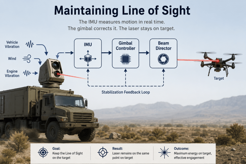
Figure 5. In a high-energy laser weapon system, the objective is not to stabilize the platform, but to stabilize the Line of Sight (LOS). Even minute angular deviations can shift the laser beam away from the intended point of impact. The IMU, gimbal controller, and beam director therefore operate as a closed-loop control system, continuously correcting beam pointing in real time.

Who Measures the Motion of the Laser System?

Consider a high-energy laser system mounted on a military vehicle.

The target is several kilometers away.

At that moment, the vehicle is far from operating in laboratory conditions.

It is continuously subjected to:

  • Engine-induced vibration
  • Suspension movement
  • Wind disturbances
  • Linear acceleration
  • Steering corrections
  • Motion of the gimbal itself

Despite all of these disturbances, the laser beam must remain focused on the same point of the target.

Before any motion can be corrected,

it must first be measured.

This is where the Inertial Measurement Unit (IMU) becomes essential.


The IMU – The Sensor Behind the Stabilization System

An Inertial Measurement Unit (IMU) continuously measures the platform’s linear acceleration and angular rate.

It does not know where the target is.

It does not control the gimbal.

It does not operate the laser.

Its role is remarkably straightforward:

Measure every motion of the platform with high accuracy and in real time.

This information is transmitted to the gimbal controller, which calculates the required correction and commands the optical assembly to move in the opposite direction.

The entire process is repeated hundreds or even thousands of times every second.


In a Laser Weapon, Even One Millisecond Matters

When discussing IMU performance, attention is often focused on accuracy.

In a high-energy laser system, however, another parameter is equally important:

Latency

In other words,

How much time passes between the moment the platform moves and the moment that information reaches the control system?

If the measurement arrives late,

the correction also arrives late.

And the beam is no longer pointing at the intended location.

This is why advanced beam steering systems require:

  • High Output Rate
  • Wide Bandwidth
  • Extremely Low Digital Delay
  • Consistent and Deterministic Timing

These are not incremental performance improvements.

They determine whether the control system corrects the motion in real time,

or simply reacts after it has already occurred.


Why Speed Matters as Much as Accuracy

Consider a driver approaching a sharp curve.

If the driver sees the turn half a second too late, it makes little difference how precise the steering system is.

The response arrives too late.

Exactly the same principle applies to laser beam stabilization.

The control system must receive motion measurements almost immediately after the platform moves.

The lower the latency, the more accurately the beam can remain locked onto the desired point of impact.


When Specifications Become Mission Performance

This is where IMU performance specifications take on operational meaning.

In a datasheet, they appear as a list of technical parameters.

In a laser interception system, they determine how effectively the beam remains on target.

IMU Specification Operational Significance
10 kHz Output Rate High-frequency motion updates for the gimbal controller
600 Hz Bandwidth Accurate measurement of high-frequency vibration and platform dynamics
Digital Delay < 20 µs Reduced control latency and improved Line of Sight stability
Low Bias Stability Reduced drift during extended target tracking
Calibration Over a Wide Temperature Range Consistent performance despite thermal changes during operation

At this point, the reader no longer sees a specification sheet.

Instead, each parameter becomes directly linked to one question:

Can the laser beam remain precisely on target long enough to complete the engagement?

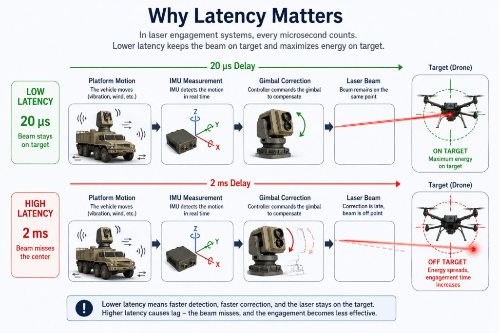
Figure 6. Comparison of low-latency and high-latency beam stabilization. Low-latency IMU measurements enable timely control corrections, maintaining accurate beam pointing throughout the engagement. Higher latency delays the control response, increasing Line of Sight error and reducing engagement effectiveness.

When Technical Specifications Meet Operational Reality

In high-energy laser interception systems, specifications such as Output Rate, Bandwidth, and Bias Stability are far more than numbers on a datasheet.

Each directly influences the system’s ability to keep the laser beam precisely on target.

For example, the LMRK006IMU from Gladiator Technologies was developed for applications requiring extremely low latency, continuous motion measurement, and long-term stability under demanding operating conditions.

Its operational significance can be summarized as follows:

IMU Specification Operational Benefit
Output Rate up to 10 kHz Provides the gimbal controller with high-frequency motion updates.
Bandwidth up to 600 Hz Captures high-frequency platform vibration as well as slower vehicle motion.
Digital Delay < 20 µs Minimizes control-loop latency, enabling earlier corrective action.
High Bias Stability Reduces drift during prolonged target tracking.
Calibration Over a Wide Temperature Range Maintains consistent performance despite temperature changes during repeated engagements.

An IMU alone, of course, does not solve the stabilization problem.

It is one element within a complete closed-loop control system that also includes the gimbal controller, servo actuators, control algorithms, and the optical assembly.

However, the quality of the motion data provided by the IMU directly determines the quality of every correction applied by the control system.


In the End, Everything Is Connected

A high-energy laser weapon can be viewed as three engineering chains operating simultaneously.

One chain delivers electrical energy.

A second manages thermal energy.

A third ensures that every photon reaches precisely the same point on the target.

If any one of these chains fails to meet its performance requirements, overall engagement effectiveness decreases, regardless of how powerful the laser source may be.

For this reason, designing a high-energy laser system does not begin with selecting the laser itself.

It begins with designing the complete system architecture – including power delivery, thermal management, closed-loop control, inertial stabilization, and optical beam steering.

Only when all of these engineering disciplines work together can the system maintain a stable, concentrated, and effective laser beam throughout the engagement.


Conclusion

A high-energy laser is far more than a powerful light source.

Behind every successful interception lies a complex engineering system in which every subsystem contributes to the final result.

The power architecture determines whether sufficient energy can be delivered at precisely the right moment.

Thermal management enables the system to sustain repeated engagements without performance degradation.

The stabilization system, supported by the IMU, ensures that the laser beam remains precisely focused on the intended point of impact.

When these three engineering disciplines are designed as a single integrated system rather than as independent subsystems, the result is a high-energy laser weapon capable of delivering consistent performance under dynamic operating conditions against small, fast-moving, and highly maneuverable targets.

Figure 7. Successful high-energy laser interception is achieved through the integration of multiple engineering disciplines operating simultaneously. The power architecture delivers the required electrical energy, the thermal management system maintains stable performance throughout the mission, and the Line of Sight (LOS) stabilization system – consisting of the IMU, gimbal controller, and optical beam director – ensures that the laser beam remains precisely focused on the target. Only when these engineering chains operate together can maximum energy density be maintained at the point of impact.

Case Study – From Engine Start to Target Intercept

Consider a typical high-energy laser weapon installed on a military vehicle operating over rough terrain.

1. Vehicle Starts Moving

The vehicle engine starts, and the onboard generator supplies electrical power to all platform subsystems.

At this stage, the electrical network may experience voltage transients, voltage sag, and other disturbances commonly found in military power systems.

↓

2. Generator Voltage Dips

As electrical loads change rapidly, the generator output voltage cannot remain perfectly stable.

Without adequate protection, these disturbances may reset sensitive electronics or interrupt mission-critical operations.

↓

3. MIL-STD-1275F Input Protection

The Input Protection module absorbs Load Dump events, limits voltage transients, and protects the entire electrical power chain in accordance with the requirements of MIL-STD-1275F.

↓

4. DC/DC Converters and Power Conditioning

Rugged DC/DC converters and Power Conditioning modules regulate the incoming electrical power, providing clean and stable supply voltages to every subsystem.

↓

5. Energy Storage Delivers Peak Power

When the firing command is issued, the Energy Storage system immediately supplies the peak power required by the laser.

Meanwhile, the generator continues to provide only the average power demand and gradually replenishes the stored energy.

Generator → Average Power

Energy Storage → Peak Power

↓

6. The IMU Remains Fully Powered

Because the supply voltage remains stable, the IMU continues measuring acceleration and angular rate without interruption or data loss.

↓

7. The Control Loop Remains Closed

IMU measurements are transmitted to the gimbal controller in real time.

IMU → Controller → Gimbal → Beam Director

The closed-loop control system continuously corrects beam pointing hundreds or even thousands of times per second.

↓

8. Line of Sight Remains Stable

Despite vehicle vibration and platform motion, the laser beam remains focused on the same point of the target.

As engagement range increases, even minute angular errors can translate into several meters of beam displacement at the target.

For this reason, Line of Sight stabilization becomes increasingly critical at long ranges.

↓

9. Successful Target Intercept

Only when the power architecture, energy storage, closed-loop control system, and Line of Sight stabilization operate together can the system maintain maximum energy density at the point of impact and achieve reliable interception under dynamic battlefield conditions.


Vehicle Starts Moving
          │
          ▼
Generator Voltage Dips
          │
          ▼
MIL-STD-1275F Input Protection
          │
          ▼
Power Conditioning
          │
          ▼
DC/DC Converters
          │
          ▼
Energy Storage
(Provides Peak Power)
          │
          ▼
Stable DC Bus
          │
     ┌────┴──────────┐
     │               │
     ▼               ▼
   Laser            IMU
                     │
                     ▼
                Controller
                     │
                     ▼
                  Gimbal
                     │
                     ▼
               Beam Director
                     │
                     ▼
          Stable Line of Sight
                     │
                     ▼
         Successful Target Intercept

Frequently Asked Questions (FAQ)

Is a high-energy laser system connected directly to the generator or battery?

Typically, no.

Between the primary energy source and the laser source is a dedicated power management architecture that includes technologies such as Input Protection, DC/DC converters, Power Conditioning, and Energy Storage.

Together, these subsystems accommodate rapid load transients, maintain stable operating voltages, and protect sensitive electronics from electrical disturbances.


Why is MIL-STD-1275F important in military laser systems?

Military vehicles operate in demanding electrical environments characterized by voltage transients, voltage sag, engine starting events, and other power disturbances.

Solutions designed to comply with MIL-STD-1275F help protect onboard electronics and ensure stable system operation under these harsh conditions.


Would installing a larger generator solve the power problem?

Not necessarily.

The primary challenge is not simply generating more power, but delivering it fast enough.

Laser firing creates rapid peak-power demands that conventional generators cannot always supply instantaneously.

For this reason, many systems incorporate Energy Storage technologies such as batteries or supercapacitors to provide immediate peak power while the generator replenishes the stored energy more gradually.


Why is thermal management as important as laser power?

Only a portion of the electrical energy supplied to a laser becomes optical output.

The remaining energy is converted into heat within the laser source, power electronics, and supporting subsystems.

Unless that heat is removed efficiently, system performance can degrade, particularly during repeated engagement cycles.


Does a more powerful cooling system always improve performance?

No.

In many precision optical systems, maintaining a uniform temperature distribution is more important than achieving the lowest possible temperature.

Thermal gradients can introduce mechanical distortion and optical misalignment, reducing pointing accuracy and beam quality.


Why is an IMU important in a laser weapon system?

The IMU continuously measures platform motion and provides real-time data to the gimbal controller.

These measurements allow the stabilization system to compensate for vibration, acceleration, and vehicle motion, maintaining a stable Line of Sight and keeping the laser beam focused on the intended point of impact.


What does latency mean in a laser interception system?

Latency is the time between platform motion and the corresponding response of the control system.

Lower latency enables corrective action to occur sooner, allowing the laser beam to remain accurately focused on the target.

Higher latency delays the correction, increasing beam pointing error and reducing engagement effectiveness.


What power solutions does Amironic provide for military platforms?

Amironic supplies a broad range of rugged power solutions for military and industrial applications, including MIL-STD-1275F Input Protection modules, rugged DC/DC converters, Power Conditioning systems, EMI/EMC filters, Electronic Circuit Protection technologies, and Power Distribution solutions.

In addition to supplying components, Amironic works with system engineers to develop power architectures tailored to the electrical and operational requirements of each application.


Glossary

Beam Director

An optical subsystem that uses mirrors or other optical elements to steer the laser beam toward the target while performing real-time beam pointing corrections.


Bias Stability

A measure of the long-term stability of an IMU. Better bias stability reduces accumulated drift during extended target tracking.


DC Bus

The primary electrical distribution bus that supplies power to voltage converters and other system subsystems.


DC/DC Converter

A power converter used to provide the voltage levels required by different subsystems within the laser system.


Electronic Circuit Protection

Protection technologies designed to safeguard electronic equipment against overcurrent, short circuits, overloads, and other electrical fault conditions.


EMI / EMC

Electromagnetic Interference (EMI) and Electromagnetic Compatibility (EMC). Military systems must continue operating reliably in electrically noisy environments without interfering with other onboard equipment.


Energy Storage

Energy storage technologies such as batteries and supercapacitors that provide the instantaneous peak power required during laser firing.


Gimbal

A stabilized mechanical assembly that directs the optical payload while compensating for platform motion and vibration.


IMU (Inertial Measurement Unit)

A sensor that continuously measures platform acceleration and angular rate, providing motion data to the stabilization and control system.


Input Protection

The first layer of the power architecture, protecting equipment against voltage transients, reverse polarity, inrush events, and other abnormal electrical conditions.


Inrush Current

A brief but high current drawn when electrical equipment is energized.


Latency

The elapsed time between a physical event, such as platform motion, and the corresponding response of the control system. Low latency is essential for maintaining stable Line of Sight.


Line of Sight (LOS)

The imaginary line connecting the laser system to the target. Maintaining LOS stability is essential for concentrating laser energy on the intended point of impact.


Load Dump

A high-voltage transient that can occur in vehicle electrical systems when a battery or major electrical load is disconnected while the generator continues supplying power.


MIL-STD-1275F

A U.S. military standard defining the electrical characteristics of military vehicle power systems and the immunity requirements for onboard electronic equipment.


Power Conditioning

Electrical circuitry that regulates and filters incoming power to improve voltage quality and protect sensitive electronics.


Power Distribution Unit (PDU)

A unit responsible for distributing and managing electrical power among multiple subsystems.


Rugged DC/DC Converter

A hardened DC/DC converter designed for military and industrial environments, capable of operating under vibration, shock, extreme temperatures, and electrical disturbances.


Thermal Gradient

A temperature difference between different regions of a system. Thermal gradients can produce mechanical deformation and optical misalignment, reducing overall system accuracy.


Voltage Sag

A temporary reduction in supply voltage that may cause instability or unintended reset of sensitive electronic equipment.


Power Density

The amount of energy delivered per unit area on the target surface. In high-energy laser applications, interception success depends not only on total laser power, but also on the ability to concentrate that energy onto the smallest possible spot and maintain it there throughout the engagement. Power Density therefore represents the combined result of effective power delivery, thermal management, and Line of Sight stabilization.

Tags: Amironic

Related Articles

Anti-Vibration Engineering – Why Machines Fail Even When The Motor, Gearbox and Control System Are Correct

25/05/2026amironicLTD

The Gearbox Isn’t the Problem – It’s Simply the First to Pay for Design Mistakes

06/07/2026amironicLTD

EMI in UAV Power Systems: When Electrical Noise Looks Like a Software Failure

09/03/2026amironicLTD

Recent Posts

  • High-Energy Laser Interception – The Engineering Behind Stable Line of Sight, Power Delivery, and Thermal Management
  • Why Do Counter-UAS Systems Lose Track of a Drone Right After Detecting It?
  • Why Programming a Rotary Position Sensor to 360° Is Sometimes the First Design Mistake
  • Don’t Design a New Footswitch – Build It from a Modular Platform
  • When GPS Is Lost, It’s Already Too Late to Choose an IMU

Categories

  • Air Switch
  • Circuit Breakers
  • Elapsed Time Indicator
  • Feedthrough
  • Footswitches
  • Gears & Transmission
  • Hour Meters
  • Infra Red Switches
  • INFRARED LAMPS
  • Low Noise Inertial MEMS
  • Mechanics
  • MEMS Gyroscope
  • MEMS Inertial
  • Microelectronics
  • Motors
  • Position Sensors
  • Power Supply
  • Pressure Sensors
  • Pressure Switch
  • Temperature Sensors
  • Tungsten and Molybdenum
  • Uncategorized
  • Vacuum Switches

Quick Contact

Fill out the form and our representatives will return to you

    Name (required)

    Email (required)

    Phone

    Message

    This site is protected by reCAPTCHA and the Google
    Privacy Policy and
    Terms of Service apply.

    Amironic Ltd.

    3 Rabinovich Street, Petah Tikva 4928144 , Israel. Tel: +972-3-9047744 E-mail: office@amironic.co.il
    Email
    Facebook
    Twitter
    LinkedIn
    YouTube
    Press on the ISO Certificate below for download
    ISO 9001:2015 Certification
    • MEMS Inertial
    • Circuit Breakers
    • Footswitches
    • Mechanical & Transmisions
    • Sensors
    • Motors
    • Electronics
    • Hand Control
    • Power Solutions

    News

    • High-Energy Laser Interception – The Engineering Behind Stable Line of Sight, Power Delivery, and Thermal Management
    • Why Do Counter-UAS Systems Lose Track of a Drone Right After Detecting It?
    • Why Programming a Rotary Position Sensor to 360° Is Sometimes the First Design Mistake
    • Don’t Design a New Footswitch – Build It from a Modular Platform
    • When GPS Is Lost, It’s Already Too Late to Choose an IMU
    About AmironicContactעברית
    © 2022 Amironic All rights reserved. All Trademarks are the property of their respective owners.
    • Increase Font
    • Decrease Font
    • Black & White
    • Inverse Colors
    • Highlight Links
    • Regular Font
    • Reset