flagעברית
flagEnglish
3 Rabinovich St., Petah-Tikva, Israel
+972 3 9047744
office@amironic.co.il
Facebook
Twitter
LinkedIn
YouTube
  • Products
    • MEMS Inertial
      • Gyros & Accels
      • IMU
      • Inertial Navigation
      • AHRS
    • Circuit Breakers
      • Airpax Circuit Breakers
      • Electronic Circuit Breakers
      • Aircraft Circuit Breakers
      • Thermal Circuit Breakers
      • Sealing Solutions & Guards
    • Footswitches
      • Pedals & Bellows
      • USB
      • Air Switches
      • Medical
      • Modular Bases System
      • Industrial
      • Foot Potentiometers
      • Wireless
    • Mechanical & Transmisions
      • Gears
      • Sealing Solutions
      • Gearboxes
      • Couplings
      • Shafts & Bearings
      • Fasteners
      • Mechanical & Springs
      • Linear Motion
      • Anti-Vibration
    • Sensors
      • Thermostats
      • Temperature
      • Position
      • Pressure
      • Speed
      • Level Sensor
      • Load Cells
      • Flex Sensors
      • Membrane Potentiometer
    • Motors
      • Geared DC
      • Brushless DC
      • Step Motors with Gearbox
      • Torque Motors & Brushless Servo
      • DC Motors
    • Electronics
      • Xenon & IR Lamps
      • Counters & Meters
      • Microelectronics Packaging
      • Waterproof Switches
      • Micro Switches
    • Hand Control
      • Operator Controls (JOYSTICK)
      • Electrical
      • Pneumatic (Medical)
      • USB Hand Control
      • Air Push Button
      • Pressure Switch
      • IR Switch
    • Power Solutions
      • Rugged & Military Power Supply
      • Input Power Protection
      • Sealed Military Power Adaptor
      • Triple Output Military Power Supply Series – up to 250 W
    • Materials
      • Molybdenum and Advanced Alloys (TZM, MOLA, HCT)
      • Tungsten (Wolfram) and Advanced Alloys – High-Performance Materials for Extreme Conditions
      • Materials for Gears
  • Shop
  • Companies
  • About Amironic
  • News
  • Contact
Product was added to your cart

Cart

waze

Heavy Duty Foot Controls for Specialty Vehicles – An Engineer’s Guide to Foot Control Interface Design

Footswitches17/09/2026amironicLTD

Heavy Duty Controls for Vehicles and Mobile Equipment – Article Series

This article is part of a series focused on the engineering and selection of Heavy Duty Controls for specialty vehicles, mobile equipment, and harsh operating environments. For a broader understanding of foot-operated and vehicle control interfaces, explore the other guides in this series:

[Heavy Duty Foot Controls for Specialty Vehicles – An Engineer’s Guide to Foot Control Interface Design]
An engineering guide to Foot Control selection, covering Momentary and Latching operation, Proportional Control, Guards, safety footwear, Multi-Pedal configurations, and customization.

[Footswitches for Vehicles and Mobile Equipment – When Does Foot Control Make Sense?]
When should a vehicle function be operated by foot? A practical look at where Footswitches make sense and the key factors to consider when designing a foot-operated interface.

[Switches and Controls for Special Purpose Vehicles – Heavy Duty Controls for Harsh Environments]
A broader guide to switches and operator controls for special purpose vehicles, with emphasis on the operator, environmental conditions, durability, and system integration.
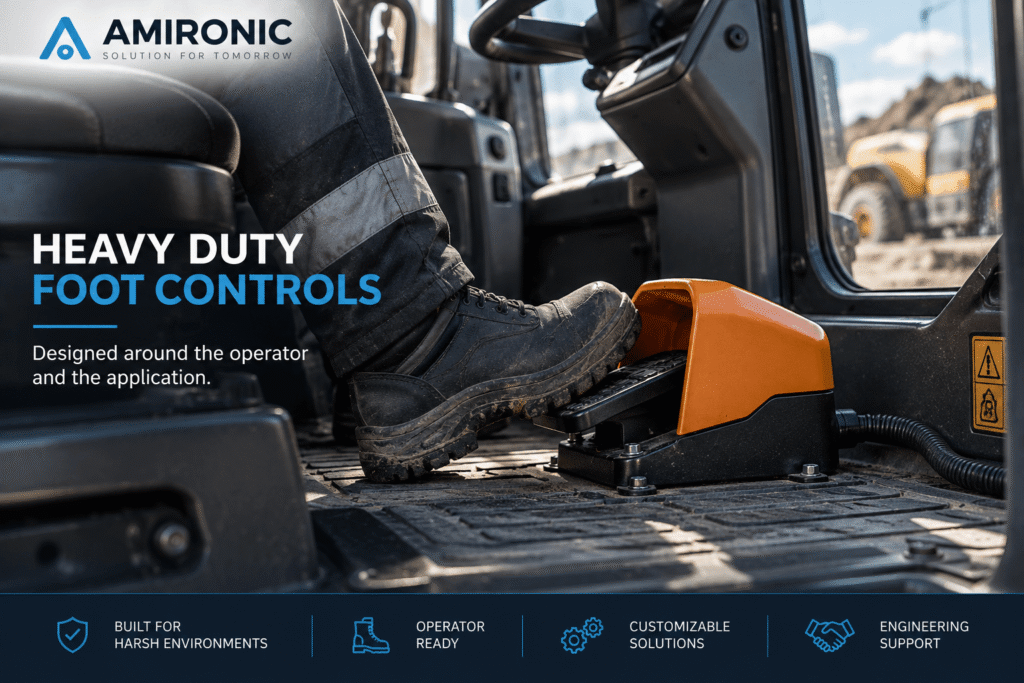
For a specialty vehicle, a Foot Control is more than just a switch operated by foot.

It is part of the vehicle’s Human-Machine Interface (HMI), so selecting the right Foot Control requires more than checking electrical ratings. The operator, the task, the operating environment, and the way the control integrates into the overall system must all be considered.

The operator may be wearing safety shoes and working in an environment exposed to vibration, dust, water, and mud. The same operation may need to be performed hundreds of times during a working day, while in other applications accidental activation may need to be carefully prevented. In some systems, the foot is not simply used for an ON/OFF command, but for proportional control of a machine function.

Therefore, even after deciding to use a Foot Control, several engineering decisions still need to be made.

Should the control be Momentary or Latching? Is one switching stage sufficient, or are multiple stages required? Is a Guard needed? What contact configuration is required? Does the system need an ON/OFF command or Proportional Control? How will the Foot Control connect to the system? And what are the requirements for environmental protection, durability, and maintenance?

In this guide, we examine these questions from the perspective of an engineer designing specialty vehicles, mobile machinery, and heavy duty equipment.

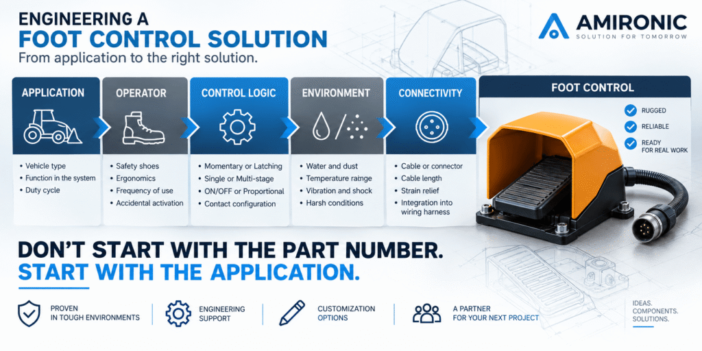
Don’t Start with the Footswitch – Start with the Function

The first question when designing a Foot Control interface should not be:

“Which Footswitch should I choose?”

Instead, ask:

“Which function do we want the operator to control with their foot?”

This distinction is important because two functions operated by foot may require completely different Foot Controls.

A function that should remain active only while the operator presses the pedal is different from one that must remain active after the pedal is released. A binary command is different from proportional control. And a routine operation performed hundreds of times per day is very different from a function where unintended activation could create an undesirable condition.

Before selecting a Heavy Duty Foot Control, it is therefore useful to define several key requirements:

  • Is the required function ON/OFF, Momentary, Latching, or Proportional?
  • Is a single operating stage required, or multiple stages?
  • How frequently will the operator use the Foot Control?
  • Will the operator need to keep the pedal depressed for extended periods?
  • Will the operator be wearing safety shoes?
  • What are the consequences of accidental activation?
  • Is a Guard or another mechanical protection method required?
  • Is a single Foot Control required, or are multiple pedals needed for different functions?
  • What environmental conditions will the unit be exposed to?
  • How should the Foot Control interface with the vehicle’s electrical or control system?

The last point is particularly important: a Foot Control does not necessarily have to be just an ON/OFF switch.

For example, the Herga 6256 Heavy Duty Footswitch range includes configurations based on switching contacts, as well as options combining a 5kΩ or 10kΩ potentiometer with microswitches. Depending on the system requirements, the Foot Control can therefore provide more than a discrete switching command.

The same principle applies to the mechanical and functional behavior of the control. The Herga 6251 range, for example, includes Single Operation, Latching, Double Operation, and Staggered Switching configurations.

This is why Foot Control selection should not begin with a part number.

First define how the operator’s foot needs to control the system. Then translate that requirement into the appropriate Foot Control.

Momentary, Latching, or Multiple Operating Stages – Foot Control Logic Starts with the Operator

Once the required function has been defined, the next question is how the Foot Control should behave during actuation and after the pedal is released.

In a foot-operated interface, this decision has both functional and ergonomic implications. The operator is not simply using a foot to “press a switch.” The pedal may need to remain depressed, return immediately after actuation, move between different operating states, or activate two different stages during its travel.

Momentary – Active Only While the Pedal Is Pressed

With a Momentary Footswitch, the electrical state changes when the pedal is actuated and returns to its original state when the operator releases it.

This configuration is particularly suitable when the system function should remain directly linked to the operator’s physical action. For example, a function that should operate only while the operator’s foot remains on the pedal.

From an interface design perspective, this provides a clear advantage: releasing the pedal can become part of the operating logic itself.

However, ergonomics become increasingly important when the function must remain active for an extended period. Holding a Foot Control down continuously is very different from making a short press, so pedal geometry, foot angle, operating force, and mounting position all become more significant.

Latching – When the Pedal Does Not Need to Remain Depressed

With a Latching Footswitch, pressing the pedal can change the switch to a state that remains active after the operator removes their foot, until the intended release action occurs.

This configuration may be suitable when there is no reason for the operator to keep their foot continuously on the control.

However, selecting a Latching Footswitch is not simply a matter of convenience. The engineer must consider what should happen if the operator removes their foot, leaves the operating position, or otherwise loses physical contact with the Foot Control.

For this reason, Momentary vs. Latching is a system-level decision, not simply a choice between two types of microswitch.

The Herga 6251 Heavy Duty Footswitch range, for example, includes Single Operation, Latching, and Double Operation configurations, allowing different operating behaviors to be selected according to the required function.

What If One Pedal Press Needs to Perform More Than One Action?

This is where Foot Control design becomes more interesting.

A Foot Control does not necessarily need to have a single switching point. Double Operation and Staggered Switching configurations can provide more than one switching event during pedal actuation.

For example, the Herga 6252 Heavy Duty Footswitch range includes Single Operation and Double Operation configurations, as well as a Staggered Double Action option defined as High Force.

From a system engineering perspective, this means that a Footswitch should not always be considered simply as:

Pressed / Not Pressed

Instead, another question can be asked:

What needs to happen throughout the pedal travel?

The answer can influence the number of contacts, switching points, operating force, and the control logic connected to the Foot Control.

What About NO, NC, and Multiple Contacts?

Here too, it is better to start with the system requirements rather than the catalog.

Define which signals the control system needs to receive in each operating state, whether Normally Open, Normally Closed, or a combination of both is required, and whether a single pedal action needs to switch more than one circuit.

Herga’s Heavy Duty Foot Control ranges offer a variety of configurations. The 6256, for example, includes options such as 1 NO + 1 NC, multiple NO/NC contact pairs, Staggered configurations, and configurations with multiple switching circuits.

Therefore, the right approach is not to begin by asking:

“Do I need SPDT or DPDT?”

Instead, ask:

“Which states and signals does the control system need to detect?”

Only after the operating logic has been defined should it be translated into the appropriate contact configuration.


ON/OFF Is Not Always Enough – When Is a Proportional Foot Control Required?

In some applications, two states – active or inactive – are simply not enough.

If the operator needs continuous control over a system parameter, for example increasing or decreasing a command according to pedal travel, the Foot Control should be considered a variable input device, rather than simply a switch.

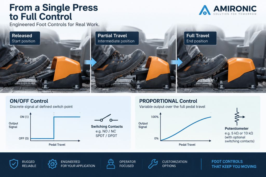
This is the key difference between Switching Control and Proportional Control.

With Switching Control, the system receives a change of state at a defined point.

With Proportional Control, the pedal position can be used to generate a signal that varies throughout the operating travel.

It is also possible to combine both functions.

The Herga 6256 range, for example, includes configurations with 5kΩ or 10kΩ potentiometers combined with snap-action microswitches and double-pole changeover contacts.

From a system design perspective, this leads to an important question. Before specifying a Footswitch, determine whether the operator’s foot is intended to activate a function or control the level of that function.

These are two different requirements, and they lead to different Foot Control architectures.

Guard, Safety Shoes, and Accidental Activation – When Mechanical Design Becomes Part of the Foot Control

Once the operating logic has been defined, the next step is to move from the electrical signal to the operator.

A Foot Control is installed in an area where the operator moves their feet, enters and exits the vehicle, and may be wearing work boots or safety shoes. One of the key questions is therefore not only how the pedal should be activated, but also how unintended activation can be prevented.

When Is a Guard Required?

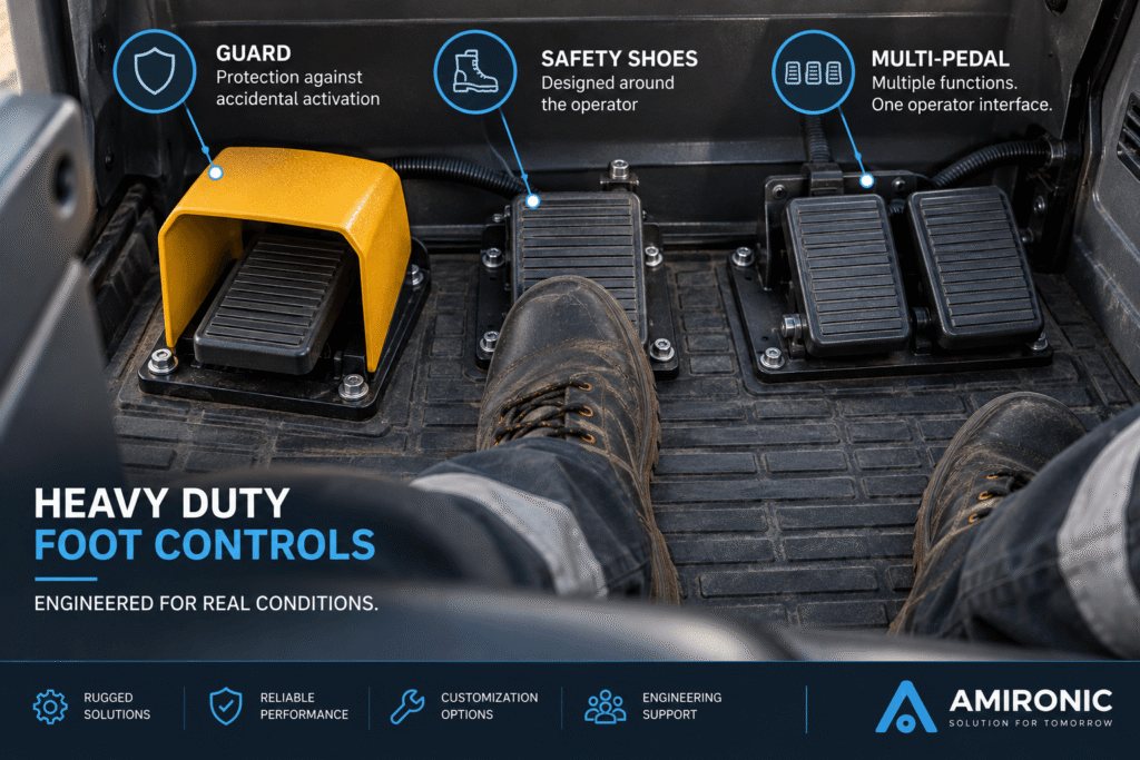
A Guard creates a mechanical barrier around the actuation area and helps reduce the possibility of the pedal being pressed by an unintended foot movement or by contact with another object.

However, adding a Guard should not be an automatic decision.

It should be evaluated as part of the application: What are the consequences of accidental activation? How frequently does the operator need to access the pedal? From what angle will it be operated? What type of footwear will the operator be wearing?

A Guard that protects the pedal effectively but makes it difficult for the operator to use it with a large safety shoe may create a new ergonomic problem.

For this reason, Protection and Accessibility should be designed together.

The Herga 6256 Heavy Duty Footswitch range, for example, includes a Guard designed to accommodate safety shoes. Herga also specifies mechanical Guard stability based on a 20 kg drop weight from a height of one meter.

The Herga 6251 range is also available with a Guard that provides space for safety footwear.

It Is Not Just About the Guard – Actuation Matters Too

Accidental activation cannot always be addressed simply by adding a metal or plastic barrier around the pedal.

Pedal travel and the force required for actuation can also form part of the design.

For example, the Herga 6252 range includes a Double Action (High Force) configuration with Staggered Switching.

From an engineering perspective, preventing unintended operation should therefore be considered as a combination of several parameters:

Position + Guard + Geometry + Actuation Method + Operating Force + Control Logic

No single parameter replaces the others.

Ergonomics – A Good Foot Control Must Fit the Operator

In a Heavy Duty application, it is easy to focus on IP Rating, current rating, and contact configuration while forgetting that the device is operated by a person.

When a Foot Control is used repeatedly, however, its mechanical design becomes an important part of the Human-Machine Interface (HMI).

Factors to consider include the pedal position relative to the operator’s seating position, foot angle during actuation, available space for footwear, the ability to rest the foot between operations, and the effort required during repeated or prolonged use.

This is also why a smaller Footswitch should not automatically be considered a better solution.

Herga uses different mechanical approaches across its Footswitch ranges. The 6229, for example, is a Low Profile Rear-Hinged Footswitch designed to improve user comfort and incorporates a Raised Tread Pattern and Anti-Slip Pad.

In comparison, Heavy Duty ranges such as the 6251 and 6256 use larger, more protected designs, with Guard options and configurations suitable for use with safety footwear.

The question is therefore not “Which pedal is better?”, but rather:

Which geometry and level of protection are appropriate for the operator and the specific working environment?

Single Foot Control or Multiple Pedals?

In a specialty vehicle or mobile machine where several functions are suitable for foot operation, each Footswitch does not necessarily have to be treated as a completely independent unit.

A Multi-Pedal Interface can also be considered.

The Herga 6256 range, for example, uses a modular design that allows individual Foot Controls to be connected using a Base Link Kit. The product documentation shows two, three, and four-pedal configurations, including options with Guards.

From an HMI design perspective, this introduces another important question: not only which functions should be operated by foot, but also how many functions should be assigned to the foot area and how the operator will distinguish between them.

When multiple pedals are used, spacing, position, Guard configuration, and the operator’s ability to identify each Foot Control without unnecessary searching all become part of the interface design.

The objective is not to add as many Foot Controls as possible.

The objective is to create an interface that allows the operator to perform the required functions naturally, consistently, and in a way that fits the task.

Case Study – Designing a Foot Control for a Heavy Duty Work Vehicle

Consider an engineer designing a specialty work vehicle with a machine function that needs to be controlled by foot.

The initial application requirements are:

  • The operator wears safety shoes.
  • The vehicle operates in an environment exposed to dust and water.
  • Both of the operator’s hands are required to operate the vehicle and its equipment.
  • Variable control is required throughout the pedal travel, rather than a simple ON/OFF command.
  • An additional switching event is required at the end of the pedal travel.
  • The risk of accidental activation should be reduced.
  • The Foot Control must integrate into the vehicle’s wiring harness.

In this type of application, simply searching for an “IP67 Footswitch” is not enough.

The application requirements need to be translated into a series of engineering decisions.

Step 1 – Is a Switch Even the Right Solution?

Because the operator needs to control the command level according to pedal travel, a conventional switch providing only two states cannot provide the required information.

A Proportional Foot Control is required.

The Herga 6256 range includes configurations combining a 5kΩ or 10kΩ potentiometer with microswitches. This makes it possible to generate a variable signal throughout the pedal travel while also incorporating switching contacts in the required configuration.

Instead of treating these as separate control requirements, the engineer can therefore consider an architecture in which the same foot-operated device provides both pedal position information and a defined switching point.

Step 2 – How Can Accidental Activation Be Reduced?

In this scenario, the pedal is located within the operator’s working area, and unintended activation is undesirable.

A Guarded Foot Control should therefore be considered.

However, the Guard needs to satisfy two requirements that can appear to conflict: it should protect the pedal from unintended actuation while still allowing the operator to access it naturally when wearing safety shoes.

The Herga 6256 is available with a Guard designed to accommodate safety shoes. Herga also specifies a Guard stability test using a 20 kg drop weight from a height of one meter.

In this application, the Guard is therefore not simply an accessory. It forms part of the operator interface design.

Step 3 – What Does the Operating Environment Require?

Another common mistake is to select a Foot Control according to its electrical function and only then determine whether it is suitable for the operating environment.

In our example, the Foot Control will be exposed to dust and water, so environmental requirements need to form part of the specification from the beginning.

The Herga 6256 range offers an IP67 option with the appropriate sealing components and specifies an operating temperature range of -20°C to +80°C, or up to +60°C for configurations where the relevant UL approval is required.

However, IP67 does not automatically mean that a Foot Control is suitable for every vehicle environment. The engineer still needs to evaluate the complete application requirements, including temperature, vibration, materials, mounting method, and actual exposure conditions.

Step 4 – How Will the Foot Control Connect to the Vehicle?

Even a Foot Control that has been correctly selected mechanically and electrically still needs to become part of the machine.

The interface should therefore be defined in advance.

What cable is required? How long should it be? Where should the cable exit the unit? Is a specific connector required? How will strain relief be handled? And during service, can the Foot Control be replaced without dismantling a significant part of the vehicle wiring harness?

Herga offers different connection options across its Foot Control ranges. The 6252, for example, can be supplied with screw terminals, stripped cable cores, or a connector of choice, while the 6251 is also available in configurations supplied with cable and connector.

From a vehicle design perspective, this is an important point: the cable and connector should not be treated as accessories added to the Foot Control at the end of the project. They are part of the Foot Control specification itself.

The Result – We Did Not Just Select a Footswitch, We Defined a Foot Control

At the end of the process, the specification looks very different from the original requirement.

Instead of:

Need Heavy Duty Footswitch

The requirement might now read:

Guarded Heavy Duty Foot Control, suitable for operation with safety shoes, proportional output with additional switching function, environmental protection suitable for the application, and a cable/connector interface defined for integration into the vehicle wiring harness.

This is the difference between selecting a component and engineering an operator interface.

The part number comes last.


Standard or Custom – When Should the Manufacturer Be Involved?

Not every application requires a Custom Foot Control.

If a standard product already provides the required actuation type, contact configuration, environmental protection, mechanical interface, and electrical connection, there is no reason to make the project unnecessarily complicated.

However, specialty vehicles and OEM equipment often have requirements that go beyond an off-the-shelf Footswitch.

The application may require a specific cordset, defined connector, custom color or marking, Guard, different switching configuration, or a combination of functions that is not available in the standard configuration.

Herga’s product ranges illustrate how customization can form part of the Foot Control design process. The 6251 range, for example, offers customer colors and logos, special designs according to customer specifications, and options for supplying the unit with a cable and connector. Other Herga ranges also offer options for cordsets, Guards, colors, and other configurable features.

For OEM projects in particular, these requirements should ideally be defined before the vehicle’s mechanical and electrical interfaces are frozen.

Changing a connector, Guard, or mounting footprint after the design has been finalized can be significantly more complicated than selecting the appropriate configuration during the early stages of the project.


Heavy Duty Foot Control Selection Checklist

Before searching for a part number, it is useful to define at least the following requirements:

Design Area What Should Be Defined?
Function What does the operator need to control?
Control Type ON/OFF or Proportional?
Action Momentary, Latching, Single, or Double Operation?
Contacts NO, NC, Changeover, or multiple circuits?
Operator Safety shoes? Repetitive operation?
Accidental Activation Is a Guard or another protection method required?
Environment Water, dust, temperature, and operating conditions
Installation Position, mounting footprint, and fixing method
Connectivity Cable type, length, connector, and cable exit
Service How will the Foot Control be replaced in the field?
Customization Is a modification from the standard product required?

The earlier these requirements are defined, the easier it becomes to move from “We need a Footswitch” to a clear engineering specification that can be matched to the appropriate Heavy Duty Foot Control solution.

Conclusion – Foot Control Is Part of the System Design

Selecting a Heavy Duty Foot Control for a specialty vehicle does not start with a part number, current rating, or even an IP Rating.

It starts with the function the operator needs to perform.

The engineer first needs to determine whether the application requires Momentary or Latching operation, an ON/OFF command or Proportional Control, one or multiple operating stages, and the appropriate contact configuration.

The next consideration is the operator. Will safety shoes be worn? Will the pedal be used frequently? Is there a risk of accidental activation? Is a Guard required? Does the application need a single Foot Control or a Multi-Pedal Interface?

Only then should environmental and integration requirements be addressed, including sealing, temperature, mechanical construction, mounting, cable, connector, serviceability, and maintenance.

The Herga product ranges demonstrate how configurable a Foot Control can be, from Momentary and Latching configurations to Single, Double, and Staggered Operation, potentiometers combined with switching contacts, Guards, Multi-Pedal configurations, and different cable and connector options.

For an OEM project, this means that the vehicle does not always have to be designed around an existing Footswitch. Where appropriate, the Foot Control configuration can be adapted to the system requirements in terms of switching, mechanical design, Guard, cordset, connector, and other features. The Herga 6251 range, for example, includes options for customer colors and logos, special designs, and configurations supplied with cable and connector.

The key principle to take from this guide is:

Don’t start with the part number. Start with the application.

When the application, operator, control logic, environmental conditions, and system interface are properly defined, selecting a Heavy Duty Foot Control becomes a structured engineering process rather than simply a component search.

Frequently Asked Questions – FAQ

What Is the Difference Between a Footswitch and a Foot Control?

A Footswitch generally refers to a device in which foot actuation changes the state of an electrical contact. Foot Control is a broader term that can also include solutions where pedal travel provides variable control.

For example, the Herga 6256 range includes configurations with switching contacts as well as options combining a 5kΩ or 10kΩ potentiometer with microswitches.

When Should I Choose a Momentary Footswitch Instead of a Latching Footswitch?

A Momentary Footswitch is suitable when the electrical state should depend directly on operator actuation and return when the pedal is released. A Latching Footswitch is suitable for applications where the selected state needs to remain after the operator removes their foot.

The choice should be based on the system logic and what should happen when the pedal is released, rather than operator convenience alone. The Herga 6251 range, for example, includes both Single Operation and Latching options.

When Is a Guard Required for a Footswitch?

A Guard can be used when the risk of unintended pedal activation needs to be reduced.

Accessibility and ergonomics must also be considered. If the operator wears safety shoes, the Guard should provide sufficient space for comfortable pedal operation. The Herga 6256, for example, is available with a Guard designed to accommodate safety footwear.

Can a Foot Control Provide Proportional Control Instead of Just ON/OFF?

Yes, in the appropriate configuration. Instead of providing only a switching point, a potentiometer can be used to generate a signal that varies according to pedal travel.

The Herga 6256 range includes 5kΩ and 10kΩ potentiometer options combined with microswitches.

Can a Footswitch Have More Than One Switching Point?

Yes, depending on the product range and configuration. Some Herga Heavy Duty Footswitch ranges include Double Operation and Staggered Switching options. The Herga 6252 also includes a Double Action configuration defined as High Force.

Can Multiple Foot Controls Be Used at the Same Operator Station?

Yes. When several machine functions are suitable for foot operation, a Multi-Pedal Interface can be considered.

The Herga 6256 range uses a modular design that allows individual units to be connected using a Base Link Kit. The product documentation shows configurations with two, three, and four pedals.

Is IP67 Enough to Define a Footswitch as Heavy Duty?

Not by itself.

An IP Rating defines enclosure protection against the ingress of solids and water according to the applicable standard. Suitability for a Heavy Duty application should also consider temperature, mechanical construction, mounting method, operating duty, and the other environmental conditions of the application.

For example, the Herga 6256 can be configured for IP67 protection and specifies an operating temperature range of -20°C to +80°C, with a different range applying to configurations requiring the relevant UL approval.

Can a Foot Control Be Supplied with a Cable and Connector for the Vehicle?

Herga Foot Control ranges offer different cable and connection options. The 6251, for example, is available with cable and connector options, while the 6252 documentation specifies screw terminals, stripped cable cores, or a connector of choice.

For an OEM project, the cable assembly and connector requirements should ideally be defined early in the design process rather than treated as additions at the end of the project.

Key Terms in Heavy Duty Foot Control Design

Term Meaning
Footswitch A foot-operated device that performs an electrical switching function.
Foot Control A broader term for a foot-operated interface that may provide switching or variable control.
Momentary The operating state is not maintained after the control is released.
Latching The selected state is maintained after actuation until the intended release or subsequent actuation occurs.
NO – Normally Open A contact that is open in its normal, non-actuated state.
NC – Normally Closed A contact that is closed in its normal, non-actuated state.
Changeover A contact arrangement that switches between two electrical paths.
SPDT / DPCO Changeover contact configurations using one or two poles, depending on the terminology used by the manufacturer.
Single Operation A single switching action during pedal actuation.
Double Operation A configuration providing more than one switching event or stage during pedal actuation.
Staggered Switching Switching points that occur at different stages rather than simultaneously.
Proportional Control A control in which the output varies according to pedal position or travel.
Potentiometer A variable resistance device that can be used to generate a position-dependent signal.
Guard A mechanical barrier around the actuation area that helps reduce accidental activation.
Multi-Pedal A configuration combining multiple Foot Controls at one operator station.
IP Rating A classification defining enclosure protection against the ingress of solids and water.
Cordset A cable assembly installed as part of the Foot Control, sometimes including a connector.
Strain Relief A mechanical feature designed to reduce the transfer of pulling or bending loads to the cable termination.
Customization Adapting the product configuration to the application, such as switching, Guard, cable/connector, color, marking, or other manufacturer-supported options.

Engineering Note: Always use the manufacturer’s exact terminology when preparing a final specification rather than relying solely on generic terms. Herga documentation, for example, uses terms including SPCO, DPCO, DPST, Single Operation, Double Operation, and Staggered depending on the specific product range and configuration.

Tags: Herga

Related Articles

Pneumatic Footswitches in Medical and Aesthetic Equipment

04/03/2026amironicLTD

Switches and Controls for Special Purpose Vehicles – Heavy Duty Controls for Harsh Environments

17/09/2026amironicLTD

Herga’s USB footswitch provides fine control for epiCam retinal camera

23/09/2016amironicLTD

Recent Posts

  • Heavy Duty Foot Controls for Specialty Vehicles – An Engineer’s Guide to Foot Control Interface Design
  • Switches and Controls for Special Purpose Vehicles – Heavy Duty Controls for Harsh Environments
  • Footswitches for Vehicles and Mobile Equipment – When Does Foot Control Make Sense?
  • Waterproof Switches for Military and Industrial Systems – CPI B2000 Series Overview and B2030-15 Case Study
  • When the Mission Goes High-Dynamic: What Happens to a Tactical IMU Under Extreme Motion?

Categories

  • Air Switch
  • Circuit Breakers
  • Elapsed Time Indicator
  • Feedthrough
  • Footswitches
  • Gears & Transmission
  • Hour Meters
  • Infra Red Switches
  • INFRARED LAMPS
  • Low Noise Inertial MEMS
  • Mechanics
  • MEMS Gyroscope
  • MEMS Inertial
  • Microelectronics
  • Motors
  • Position Sensors
  • Power Supply
  • Pressure Sensors
  • Pressure Switch
  • Switches
  • Temperature Sensors
  • Tungsten and Molybdenum
  • Uncategorized
  • Vacuum Switches

Quick Contact

Fill out the form and our representatives will return to you

    Name (required)

    Email (required)

    Phone

    Message

    This site is protected by reCAPTCHA and the Google
    Privacy Policy and
    Terms of Service apply.

    Amironic Ltd.

    3 Rabinovich Street, Petah Tikva 4928144 , Israel. Tel: +972-3-9047744 E-mail: office@amironic.co.il
    Email
    Facebook
    Twitter
    LinkedIn
    YouTube
    Press on the ISO Certificate below for download
    ISO 9001:2015 Certification
    • MEMS Inertial
    • Circuit Breakers
    • Footswitches
    • Mechanical & Transmisions
    • Sensors
    • Motors
    • Electronics
    • Hand Control
    • Power Solutions

    News

    • Heavy Duty Foot Controls for Specialty Vehicles – An Engineer’s Guide to Foot Control Interface Design
    • Switches and Controls for Special Purpose Vehicles – Heavy Duty Controls for Harsh Environments
    • Footswitches for Vehicles and Mobile Equipment – When Does Foot Control Make Sense?
    • Waterproof Switches for Military and Industrial Systems – CPI B2000 Series Overview and B2030-15 Case Study
    • When the Mission Goes High-Dynamic: What Happens to a Tactical IMU Under Extreme Motion?
    About AmironicContactעברית
    © 2022 Amironic All rights reserved. All Trademarks are the property of their respective owners.
    • Increase Font
    • Decrease Font
    • Black & White
    • Inverse Colors
    • Highlight Links
    • Regular Font
    • Reset