Introduction – Two Technologies, One Goal: Accurate Acceleration Measurement
Accelerometers are essential components in inertial navigation systems, stabilization platforms, robotics, unmanned aerial vehicles (UAVs), precision measurement equipment, and advanced industrial systems.
Although all accelerometers are designed to measure acceleration, significant differences exist in how they perform this measurement. One of the most important distinctions is between two sensing architectures: Open-Loop and Closed-Loop.
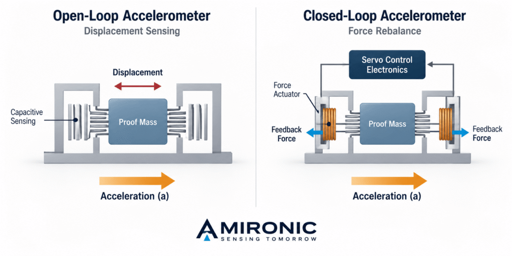
In Open-Loop systems, acceleration is measured through the response of a microscopic mechanical structure to applied forces. In contrast, Closed-Loop systems use a feedback mechanism that applies a counteracting force to the sensing mass, keeping it close to its equilibrium position.
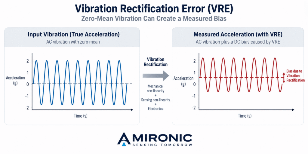
The choice between these approaches affects several important engineering characteristics, including measurement noise, Bias Stability, Scale Factor accuracy, Dynamic Range, Vibration Rectification, and power consumption.
However, contrary to the assumption that Closed-Loop technology is inherently more accurate, the reality is more complex. An advanced Open-Loop accelerometer can deliver excellent noise and stability performance, sometimes outperforming Closed-Loop sensors in specific parameters.
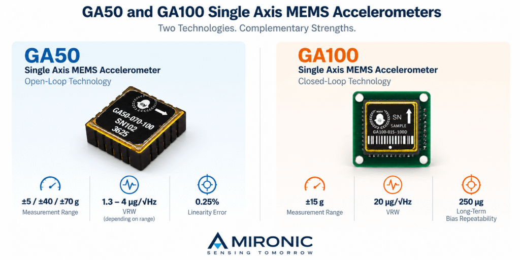
Gladiator Technologies, a manufacturer specializing in MEMS-based inertial sensors, offers solutions based on both architectures. The GA50 series represents an ultra-low-noise Open-Loop architecture, while the GA100 utilizes Closed-Loop technology with a Force-Rebalance mechanism designed for accurate and stable acceleration measurements.
In this article, we examine the operating principles of both technologies, analyze their advantages and limitations, and compare the performance specifications of Gladiator Technologies accelerometers to help engineers select the most suitable solution for their applications.
1. Operating Principles of MEMS Accelerometers
MEMS, short for Micro-Electro-Mechanical Systems, is a technology that enables the integration of microscopic mechanical structures and electronic circuits into compact devices.
At the heart of a typical MEMS accelerometer is a small mass known as the Proof Mass, connected to the sensor frame through flexible mechanical elements.
When the accelerometer experiences acceleration, the proof mass responds to the resulting inertial force, creating relative motion between the mass and the sensor frame. This motion can be detected using various sensing mechanisms, such as Capacitive Sensing.
The fundamental relationship between force and acceleration is described by Newton’s second law:
F = m × a
Where:
-
F – Force, measured in newtons (N).
-
m – Proof mass, measured in kilograms (kg).
-
a – Acceleration, measured in meters per second squared (m/s²).
In practice, the behavior of the proof mass is also influenced by the mechanical stiffness, damping, and frequency of the applied acceleration.
A simplified model of the sensing structure can be described using a mass-spring-damper equation:
m × d²x/dt² + c × dx/dt + k × x = -m × a
Where:
-
m – Proof mass.
-
x – Relative displacement of the proof mass.
-
c – Damping coefficient.
-
k – Spring constant.
-
a – Acceleration of the sensor frame along the sensing axis.
This equation describes the relative motion of the proof mass with respect to the sensor frame, with the direction of acceleration defined according to the selected coordinate system.
It demonstrates that the sensor’s response depends not only on acceleration magnitude but also on the dynamic characteristics of its mechanical structure.
At frequencies significantly below the mechanical resonance frequency, and assuming operation within the linear range, the relative displacement of the proof mass is approximately proportional to the applied acceleration.
This principle forms the basis for the fundamental difference between Open-Loop and Closed-Loop sensing architectures.
Open-Loop – Measurement Through Proof Mass Response
In an Open-Loop accelerometer, acceleration is calculated from the response of the proof mass to inertial forces, without applying a feedback force to rebalance its motion.
The electronics measure the resulting physical change in the sensing structure and convert it into an electrical signal representing acceleration.
One advantage of this approach is the ability to implement a relatively simple sensing system without requiring a control loop that applies a balancing force to the proof mass.
However, because the measurement depends on the mechanical response of the sensing structure, sensor performance may be influenced by factors such as stiffness, damping, linearity, and sensitivity to temperature variations.
Advanced mechanical and electronic design, combined with appropriate calibration, can minimize these effects and achieve high performance without a force-feedback system.
An example is the GA50 series from Gladiator Technologies, which offers Open-Loop accelerometers with measurement ranges of ±5g, ±40g, and ±70g, delivering low noise and high stability for precision inertial applications.
Closed-Loop – Measurement Through Force Rebalancing
In a Closed-Loop accelerometer using Force-Rebalance technology, the control system detects proof mass displacement and applies an opposing force to minimize its movement.
Rather than relying primarily on displacement magnitude, acceleration can be estimated from the balancing force required to maintain the proof mass near its reference position.
In an ideal system operating at equilibrium, the feedback force balances the inertial force:
F_feedback ≈ m × a
Where F_feedback represents the magnitude of the balancing force applied by the feedback system, and a represents the measured acceleration.
This approach can improve linearity, reduce the measurement’s dependence on certain mechanical characteristics, and enhance performance under dynamic conditions, depending on the sensor and control system design.
One potential advantage is the ability to minimize proof mass displacement even when the accelerometer is subjected to varying acceleration levels. This can reduce certain error mechanisms associated with large mechanical displacements.
However, the feedback system introduces additional electronic components, control mechanisms, and potential sources of noise and measurement errors. Its performance also depends on the bandwidth, stability, and accuracy of the feedback control loop.
An example of this technology is the GA100 from Gladiator Technologies, a single-axis Closed-Loop MEMS accelerometer utilizing a Force-Rebalance mechanism.
According to the manufacturer’s specifications, the GA100 offers a measurement range of ±15g, Long-Term Bias Repeatability of 250 µg, and a Vibration Rectification coefficient of 25 µg/(g RMS)².
These specifications highlight the GA100’s focus on measurement stability and reduced errors under demanding operating conditions.
It is important to emphasize that Closed-Loop technology does not automatically guarantee superior performance in every parameter. A proper engineering comparison must be based on actual sensor specifications, considering measurement range, noise, stability, environmental conditions, and application requirements.