flagעברית
flagEnglish
3 Rabinovich St., Petah-Tikva, Israel
+972 3 9047744
office@amironic.co.il
Facebook
Twitter
LinkedIn
YouTube
  • Products
    • MEMS Inertial
      • Gyros & Accels
      • IMU
      • Inertial Navigation
      • AHRS
    • Circuit Breakers
      • Airpax Circuit Breakers
      • Electronic Circuit Breakers
      • Aircraft Circuit Breakers
      • Thermal Circuit Breakers
      • Sealing Solutions & Guards
    • Footswitches
      • Pedals & Bellows
      • USB
      • Air Switches
      • Medical
      • Modular Bases System
      • Industrial
      • Foot Potentiometers
      • Wireless
    • Mechanical & Transmissions
      • Gears
      • Sealing Solutions
      • Gearboxes
      • Couplings
      • Shafts & Bearings
      • Fasteners
      • Mechanical & Springs
      • Linear Motion
      • Anti-Vibration
    • Sensors
      • Thermostats
      • Temperature
      • Position
      • Pressure
      • Speed
      • Level Sensor
      • Load Cells
      • Flex Sensors
      • Membrane Potentiometer
    • Motors
      • Geared DC
      • Brushless DC
      • Step Motors with Gearbox
      • Torque Motors & Brushless Servo
      • DC Motors
    • Electronics
      • Xenon & IR Lamps
      • Counters & Meters
      • Microelectronics Packaging
      • Waterproof Switches
      • Micro Switches
    • Hand Control
      • Operator Controls (JOYSTICK)
      • Electrical
      • Pneumatic (Medical)
      • USB Hand Control
      • Air Push Button
      • Pressure Switch
      • IR Switch
    • Power Solutions
      • Rugged & Military Power Supply
      • Input Power Protection
      • Sealed Military Power Adaptor
      • Triple Output Military Power Supply Series – up to 250 W
    • Materials
      • Molybdenum and Advanced Alloys (TZM, MOLA, HCT)
      • Tungsten (Wolfram) and Advanced Alloys – High-Performance Materials for Extreme Conditions
      • Materials for Gears
  • Shop
  • Companies
  • About Amironic
  • News
  • Contact
Product was added to your cart

Cart

waze

Open-Loop vs. Closed-Loop Accelerometers – Which Technology Is Right for Your Application?

MEMS Inertial29/10/2026amironicLTD

Introduction – Two Technologies, One Goal: Accurate Acceleration Measurement

Accelerometers are essential components in inertial navigation systems, stabilization platforms, robotics, unmanned aerial vehicles (UAVs), precision measurement equipment, and advanced industrial systems.

Although all accelerometers are designed to measure acceleration, significant differences exist in how they perform this measurement. One of the most important distinctions is between two sensing architectures: Open-Loop and Closed-Loop.

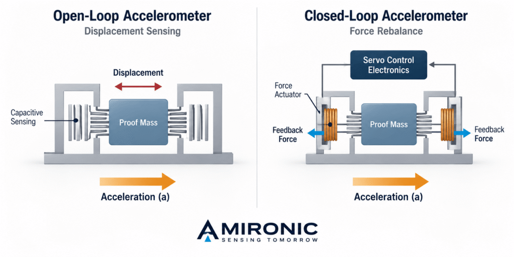
In Open-Loop systems, acceleration is measured through the response of a microscopic mechanical structure to applied forces. In contrast, Closed-Loop systems use a feedback mechanism that applies a counteracting force to the sensing mass, keeping it close to its equilibrium position.

The choice between these approaches affects several important engineering characteristics, including measurement noise, Bias Stability, Scale Factor accuracy, Dynamic Range, Vibration Rectification, and power consumption.

However, contrary to the assumption that Closed-Loop technology is inherently more accurate, the reality is more complex. An advanced Open-Loop accelerometer can deliver excellent noise and stability performance, sometimes outperforming Closed-Loop sensors in specific parameters.

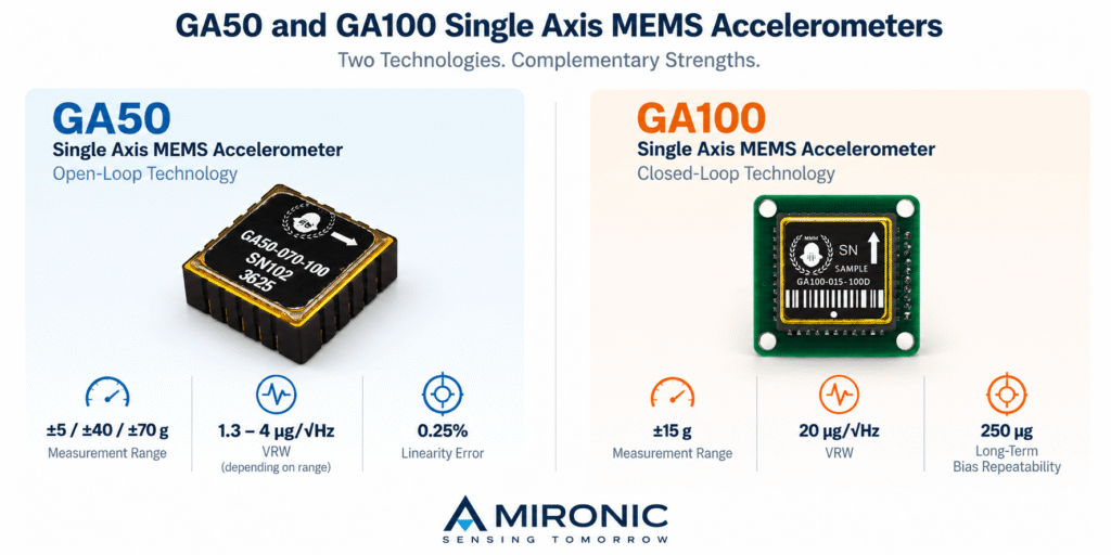
Gladiator Technologies, a manufacturer specializing in MEMS-based inertial sensors, offers solutions based on both architectures. The GA50 series represents an ultra-low-noise Open-Loop architecture, while the GA100 utilizes Closed-Loop technology with a Force-Rebalance mechanism designed for accurate and stable acceleration measurements.

In this article, we examine the operating principles of both technologies, analyze their advantages and limitations, and compare the performance specifications of Gladiator Technologies accelerometers to help engineers select the most suitable solution for their applications.

1. Operating Principles of MEMS Accelerometers

MEMS, short for Micro-Electro-Mechanical Systems, is a technology that enables the integration of microscopic mechanical structures and electronic circuits into compact devices.

At the heart of a typical MEMS accelerometer is a small mass known as the Proof Mass, connected to the sensor frame through flexible mechanical elements.

When the accelerometer experiences acceleration, the proof mass responds to the resulting inertial force, creating relative motion between the mass and the sensor frame. This motion can be detected using various sensing mechanisms, such as Capacitive Sensing.

The fundamental relationship between force and acceleration is described by Newton’s second law:

F = m × a

Where:

  • F – Force, measured in newtons (N).

  • m – Proof mass, measured in kilograms (kg).

  • a – Acceleration, measured in meters per second squared (m/s²).

In practice, the behavior of the proof mass is also influenced by the mechanical stiffness, damping, and frequency of the applied acceleration.

A simplified model of the sensing structure can be described using a mass-spring-damper equation:

m × d²x/dt² + c × dx/dt + k × x = -m × a

Where:

  • m – Proof mass.

  • x – Relative displacement of the proof mass.

  • c – Damping coefficient.

  • k – Spring constant.

  • a – Acceleration of the sensor frame along the sensing axis.

This equation describes the relative motion of the proof mass with respect to the sensor frame, with the direction of acceleration defined according to the selected coordinate system.

It demonstrates that the sensor’s response depends not only on acceleration magnitude but also on the dynamic characteristics of its mechanical structure.

At frequencies significantly below the mechanical resonance frequency, and assuming operation within the linear range, the relative displacement of the proof mass is approximately proportional to the applied acceleration.

This principle forms the basis for the fundamental difference between Open-Loop and Closed-Loop sensing architectures.

Open-Loop – Measurement Through Proof Mass Response

In an Open-Loop accelerometer, acceleration is calculated from the response of the proof mass to inertial forces, without applying a feedback force to rebalance its motion.

The electronics measure the resulting physical change in the sensing structure and convert it into an electrical signal representing acceleration.

One advantage of this approach is the ability to implement a relatively simple sensing system without requiring a control loop that applies a balancing force to the proof mass.

However, because the measurement depends on the mechanical response of the sensing structure, sensor performance may be influenced by factors such as stiffness, damping, linearity, and sensitivity to temperature variations.

Advanced mechanical and electronic design, combined with appropriate calibration, can minimize these effects and achieve high performance without a force-feedback system.

An example is the GA50 series from Gladiator Technologies, which offers Open-Loop accelerometers with measurement ranges of ±5g, ±40g, and ±70g, delivering low noise and high stability for precision inertial applications.

Closed-Loop – Measurement Through Force Rebalancing

In a Closed-Loop accelerometer using Force-Rebalance technology, the control system detects proof mass displacement and applies an opposing force to minimize its movement.

Rather than relying primarily on displacement magnitude, acceleration can be estimated from the balancing force required to maintain the proof mass near its reference position.

In an ideal system operating at equilibrium, the feedback force balances the inertial force:

F_feedback ≈ m × a

Where F_feedback represents the magnitude of the balancing force applied by the feedback system, and a represents the measured acceleration.

This approach can improve linearity, reduce the measurement’s dependence on certain mechanical characteristics, and enhance performance under dynamic conditions, depending on the sensor and control system design.

One potential advantage is the ability to minimize proof mass displacement even when the accelerometer is subjected to varying acceleration levels. This can reduce certain error mechanisms associated with large mechanical displacements.

However, the feedback system introduces additional electronic components, control mechanisms, and potential sources of noise and measurement errors. Its performance also depends on the bandwidth, stability, and accuracy of the feedback control loop.

An example of this technology is the GA100 from Gladiator Technologies, a single-axis Closed-Loop MEMS accelerometer utilizing a Force-Rebalance mechanism.

According to the manufacturer’s specifications, the GA100 offers a measurement range of ±15g, Long-Term Bias Repeatability of 250 µg, and a Vibration Rectification coefficient of 25 µg/(g RMS)².

These specifications highlight the GA100’s focus on measurement stability and reduced errors under demanding operating conditions.

It is important to emphasize that Closed-Loop technology does not automatically guarantee superior performance in every parameter. A proper engineering comparison must be based on actual sensor specifications, considering measurement range, noise, stability, environmental conditions, and application requirements.
2. Measurement Noise (Noise and VRW) – Is Closed-Loop Really Quieter?

One of the most important parameters when selecting a precision accelerometer is the sensor’s internal noise level.

Even when an accelerometer is completely stationary, its output signal is not perfectly constant. Small random fluctuations arise from mechanical and electronic noise sources, including thermal noise, sensing circuit noise, and signal processing electronics.

This noise affects the ability to detect small accelerations and the accuracy of measurements, particularly in applications where velocity or position must be calculated by integrating acceleration data.

What Is VRW – Velocity Random Walk?

One of the commonly used metrics for characterizing noise in inertial accelerometers is Velocity Random Walk (VRW).

When the sensor’s noise spectral density is approximately constant across the relevant frequency range, it can be expressed in units of µg/√Hz.

The lower this value, the lower the random measurement noise.

For example, an accelerometer with a noise density of 2 µg/√Hz is expected to exhibit lower acceleration noise than a sensor rated at 20 µg/√Hz, assuming identical measurement conditions, bandwidth, and metric definitions.

When acceleration data is integrated to calculate velocity, random noise introduces a velocity error whose standard deviation increases approximately with the square root of the measurement duration.

Therefore, low VRW is particularly important in inertial navigation systems, precision measurement equipment, and applications requiring the detection of very small acceleration changes.

Does Closed-Loop Technology Reduce Noise?

Closed-Loop technology controls proof mass motion through a feedback force, but this does not necessarily reduce the overall noise level.

The feedback system itself may introduce additional noise sources, including noise from control circuits, force actuation mechanisms, and measurement electronics.

In contrast, a well-designed Open-Loop accelerometer can achieve exceptionally low noise through optimization of the mechanical structure, sensing circuits, and signal processing techniques.

This means that noise performance should be compared using actual sensor specifications rather than sensing architecture alone.

Practical Example – GA50 vs. GA100

The GA50 series from Gladiator Technologies demonstrates how extremely low noise can be achieved using an Open-Loop architecture.

According to the manufacturer’s specifications, the accelerometers offer the following measurement ranges and noise performance:

Model Measurement Range VRW
GA50 ±5g 1.3 µg/√Hz
GA50 ±40g 2.5 µg/√Hz
GA50 ±70g 4 µg/√Hz
GA100 ±15g 20 µg/√Hz

These specifications show that the GA50 series offers lower stated noise density than the GA100, despite using Open-Loop technology.

For example, the ±5g version of the GA50 achieves a VRW value of 1.3 µg/√Hz, compared with 20 µg/√Hz for the GA100.

This represents a significant difference in the stated noise performance. However, the sensors have different measurement ranges and are not otherwise identical, so the comparison should not be interpreted as a universal advantage of one architecture.

The GA100 is not necessarily designed to achieve the lowest possible noise level. Instead, it offers a different combination of performance characteristics, including long-term stability, repeatability, and reduced sensitivity to certain error mechanisms.

Engineering Takeaway: When measurement noise is the primary requirement, there is no reason to automatically favor Closed-Loop technology. Engineers should evaluate the specified noise density and sensor performance across the frequency range relevant to their application.

3. Measurement Stability – Bias Stability and Bias Repeatability

Low measurement noise does not necessarily guarantee high accuracy over time.

An accelerometer may exhibit exceptionally low random noise while still experiencing changes in its measurement bias, potentially resulting in accumulated errors.

Bias is a measurement offset that causes the accelerometer to report acceleration different from the actual acceleration, even after accounting for measurement conditions and calibration.

In inertial navigation systems, bias errors can be particularly significant because their effects accumulate when calculating velocity and position.

Bias Stability – Understanding Measurement Drift

Bias Stability describes how consistently an accelerometer maintains its bias over a specified period.

The more stable the bias, the easier it is to maintain measurement accuracy following calibration.

However, several different stability and repeatability parameters must be distinguished:

  • Short-Term Stability – Bias stability over relatively short periods, according to specified test conditions.

  • In-Run Bias Stability – Bias stability during continuous sensor operation.

  • Long-Term Bias Repeatability – Bias repeatability over extended periods, according to the manufacturer’s measurement and testing procedures.

  • Turn-On to Turn-On Repeatability – Variation in sensor bias between successive power-up cycles.

These parameters are not interchangeable and should not be compared directly without understanding their measurement methods.

Stability Comparison – GA50 vs. GA100

According to Gladiator Technologies, the GA50 series offers the following stability specifications:

Parameter GA50 ±5g GA50 ±40g GA50 ±70g
Short-Term Stability 60 µg 120 µg 180 µg
Long-Term Bias Repeatability 800 µg 4,000 µg 7,000 µg
Turn-On to Turn-On Repeatability 50 µg 120 µg 240 µg

For the GA100, the manufacturer’s performance presentation specifies:

  • Long-Term Bias Repeatability of 250 µg.

  • Long-Term Scale Factor of 400 ppm.

  • Short-Term Stability listed as 7/60 µg, without further clarification in the presentation regarding the meaning of the two values.

The GA100’s stated Long-Term Bias Repeatability is significantly lower than the corresponding values listed for the GA50 variants.

This may provide an advantage in applications requiring highly repeatable acceleration measurements over extended periods, particularly when frequent recalibration is impractical.

However, these differences do not establish that every Closed-Loop accelerometer offers better stability than every Open-Loop sensor.

Actual stability depends on mechanical design, electronics, temperature variations, calibration procedures, and environmental conditions.

Why Is Bias So Important in Inertial Navigation?

Consider an accelerometer with a constant bias error of 100 µg.

This error corresponds to approximately 0.000981 m/s² of acceleration.

After 60 seconds of integration, assuming the bias remains constant, the resulting velocity error is approximately 0.059 m/s.

If the acceleration signal is integrated again to calculate position, the resulting position error reaches approximately 1.77 meters after 60 seconds.

This example considers only the effect of a constant bias error, excluding additional error sources such as random noise, alignment errors, gyroscope errors, and temperature variations.

In real inertial navigation systems, these error mechanisms act simultaneously, making it essential to evaluate the sensor’s overall performance.

Engineering Takeaway: When an application requires long-term measurement accuracy, engineers must evaluate not only noise performance but also Bias Stability, Bias Repeatability, and sensor behavior under the expected environmental conditions.

4. Dynamic Range, Linearity, and Scale Factor – How Does Architecture Affect Measurement Accuracy?

Beyond noise and bias stability, two key considerations when selecting an accelerometer are its Measurement Range and the accuracy with which it converts physical acceleration into an electrical signal.

Some applications require extremely precise measurements of small accelerations, while others must accommodate significant acceleration levels, rapid motion changes, and dynamic loads.

The engineering challenge is to combine an appropriate measurement range with high sensitivity, good linearity, and long-term stability.

4.1 Measurement Range

Measurement Range defines the acceleration limits within which a sensor is designed to operate according to the manufacturer’s specifications.

For example, an accelerometer rated at ±15g is designed to measure positive and negative accelerations up to 15g along its sensing axis.

It is important to distinguish Measurement Range from Shock Survivability. A sensor may survive acceleration levels significantly higher than its specified measurement range without being capable of accurately measuring those levels.

The GA50 series from Gladiator Technologies is available in three measurement ranges:

  • ±5g – For applications requiring high sensitivity to relatively small accelerations.

  • ±40g – For dynamic applications requiring a wider acceleration range.

  • ±70g – For systems expected to experience higher acceleration levels during operation.

In comparison, the Closed-Loop GA100 is presented with a measurement range of ±15g.

These differences do not necessarily reflect fundamental limitations of either technology. Instead, they result from sensor design decisions and the requirements for which each device was developed.

Both Open-Loop and Closed-Loop accelerometers can be designed for a wide variety of measurement ranges.

4.2 Linearity

Linearity describes how closely the relationship between physical acceleration and sensor output follows an ideal linear response.

In an ideal accelerometer, doubling the applied acceleration produces a corresponding doubling of the change in output signal.

In practice, accelerometers may exhibit nonlinear behavior due to mechanical structure characteristics, sensing mechanisms, electronics, and signal processing methods.

In an Open-Loop accelerometer, the proof mass moves relative to the sensor frame in response to applied acceleration. As displacement increases, nonlinear characteristics of the mechanical structure or sensing mechanism may affect measurement accuracy.

In a Closed-Loop Force-Rebalance accelerometer, the feedback system works to maintain the proof mass near its reference position.

Reducing displacement can minimize certain errors associated with large mechanical movements, potentially improving linearity.

However, Closed-Loop systems are not perfectly linear either. Measurement accuracy also depends on the linearity of the force actuation mechanism, control electronics, and calibration procedures.

According to the GA50 datasheet, Gladiator Technologies specifies a Linearity Error of 0.25% across all three measurement ranges.

The supplied GA100 performance presentation does not provide an explicit numerical Linearity Error specification. Therefore, the available information does not support a quantitative comparison of linearity between the two sensors.

4.3 What Is Scale Factor?

Scale Factor describes the relationship between physical acceleration and the resulting change in sensor output.

For an accelerometer with an analog output, Scale Factor may be expressed in mV/g, representing the number of millivolts generated per 1g change in acceleration.

For example, if a sensor has a sensitivity of 100 mV/g and experiences an acceleration change of 2g, the ideal output change is 200 mV.

For accelerometers with digital outputs, Scale Factor may be represented as the relationship between digital output values and physical acceleration.

Scale Factor errors introduce measurement errors proportional to the magnitude of acceleration.

Unlike Bias Error, which adds an offset to the measurement, Scale Factor Error affects the proportional relationship between actual and reported acceleration.

For example, a Scale Factor Error of 400 ppm corresponds to a relative error of 0.04%.

At an acceleration of 10g, this relative error may produce a measurement error of 0.004g, or 4mg, assuming no appropriate correction has been applied.

4.4 Long-Term Scale Factor Stability

Beyond the nominal Scale Factor value, its stability over time is also important.

Changes in Scale Factor may result from temperature variations, component aging, mechanical stresses, and changes in the sensing system’s characteristics.

The GA50 datasheet specifies Long-Term Scale Factor Repeatability of 600 ppm for all three measurement ranges.

The GA100 performance presentation lists a Long-Term Scale Factor value of 400 ppm.

These values indicate different stated performance characteristics. However, a direct comparison requires confirmation that the measurement methods, test conditions, and parameter definitions are equivalent.

4.5 Performance Comparison – GA50 vs. GA100

Parameter GA50 Open-Loop GA100 Closed-Loop
Measurement Range ±5g, ±40g, ±70g ±15g
Linearity Error 0.25% Not numerically specified
Long-Term Scale Factor 600 ppm repeatability 400 ppm, as listed in the presentation
Measurement Principle Proof mass response to acceleration Force-Rebalance
Output Interface Analog SPI, according to AUSA 2026 presentation

These specifications apply to the particular products shown and should not be generalized to all accelerometers using the same sensing architecture.

Engineering Takeaway: Closed-Loop technology may offer advantages in linearity and Scale Factor stability. However, accelerometer selection should be based on application requirements and verified performance specifications rather than architecture alone.

5. Vibration Sensitivity – Vibration Rectification Error (VRE)

One of the most important error mechanisms in precision accelerometers is Vibration Rectification Error (VRE).

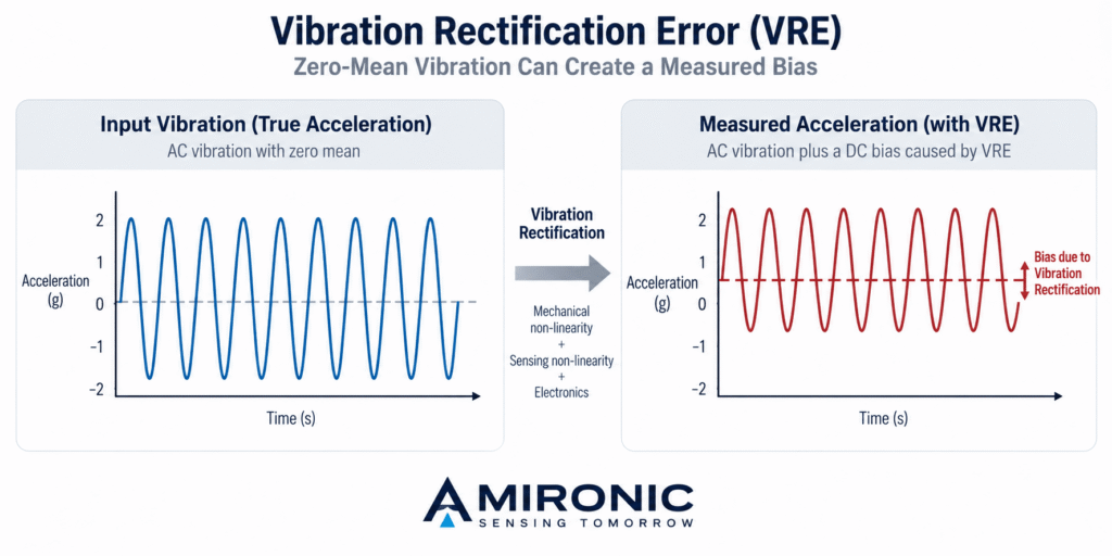
VRE occurs when periodic or random mechanical vibrations introduce an average offset into the measured acceleration signal.

In other words, even when the vibration itself has zero mean acceleration, the accelerometer may report a constant or slowly varying acceleration offset due to nonlinear effects.

This phenomenon is particularly important in systems exposed to significant mechanical vibration, including aircraft, ground vehicles, propulsion systems, industrial equipment, and stabilization platforms.

5.1 How Does Vibration Rectification Error Occur?

When an accelerometer is subjected to vibration, the proof mass responds to the changing acceleration forces.

In an ideal linear system, vibration that is symmetric around zero should not produce an average acceleration error.

However, real accelerometers may exhibit nonlinear mechanisms, including:

  • Nonlinear behavior of the sensor’s mechanical structure.

  • Nonlinearity in the sensing mechanism.

  • Asymmetric response to positive and negative accelerations.

  • Mechanical resonance effects and high-frequency vibration components.

  • Limitations in the measurement electronics or feedback control system.

As a result, vibration may generate an additional bias error even when the average acceleration of the vibration itself is zero.

This error can be especially significant in inertial navigation systems because the resulting bias may accumulate during velocity and position calculations.

5.2 How Is Vibration Rectification Measured?

The Vibration Rectification coefficient is sometimes specified in units of µg/g² RMS.

This coefficient approximately describes the relationship between vibration intensity and the resulting bias error under defined test conditions.

For example, if an accelerometer has a VRE coefficient of 25 µg/g² RMS and is exposed to vibration with an intensity of 2g RMS, the estimated bias error may reach 100 µg.

The simplified calculation is:

VRE ≈ 25 × 2² = 100 µg

This estimate is based on a simplified quadratic model. In practice, VRE also depends on vibration spectrum, frequency, excitation direction, and sensor characteristics.

Therefore, the VRE coefficient alone cannot accurately predict sensor behavior under every vibration environment.

5.3 Is Closed-Loop More Resistant to Vibration-Induced Errors?

One potential advantage of Closed-Loop technology is its ability to minimize proof mass movement through feedback control.

By maintaining the proof mass near its reference position, certain nonlinear effects associated with large mechanical displacements can be reduced.

For this reason, Force-Rebalance architectures may offer advantages in applications requiring accurate acceleration measurements in vibrating environments.

However, this does not mean that every Closed-Loop accelerometer will exhibit lower VRE than an Open-Loop sensor.

Actual performance also depends on mechanical design, resonance frequencies, feedback bandwidth, and how the electronics respond to vibration signals.

5.4 Vibration Rectification Comparison – GA50 vs. GA100

Gladiator Technologies’ specifications illustrate the differences between these accelerometers.

Accelerometer Measurement Range Vibration Rectification
GA50 Open-Loop ±5g 150 µg/g² RMS
GA50 Open-Loop ±40g 25 µg/g² RMS
GA50 Open-Loop ±70g 15 µg/g² RMS
GA100 Closed-Loop ±15g 25 µg/g² RMS

The GA100 exhibits a VRE coefficient of 25 µg/g² RMS, lower than the value specified for the ±5g GA50.

However, the ±40g GA50 has the same stated coefficient, while the ±70g version achieves a lower value of 15 µg/g² RMS.

These results demonstrate that Vibration Rectification performance is not determined by sensing architecture alone.

It is also important to remember that these accelerometers have different measurement ranges, and a complete comparison requires equivalent test conditions.

5.5 Why Is VRE Important in Navigation and Stabilization Systems?

In inertial navigation systems, VRE may be interpreted by the navigation algorithm as actual acceleration.

When acceleration data is integrated, this error can cause deviations in calculated velocity and position.

In stabilization systems, acceleration errors may affect motion estimation and control system behavior, depending on how the accelerometer data is incorporated into the algorithm.

Therefore, systems operating in vibrating environments should be evaluated for VRE performance alongside noise, Bias Stability, bandwidth, and measurement range.

Engineering Takeaway: In environments characterized by significant vibration, Vibration Rectification can be one of the deciding factors in accelerometer selection. Closed-Loop architectures may offer advantages, but actual sensor performance ultimately determines suitability for the application.

6. Open-Loop and Closed-Loop in Practical Applications – Which Technology Fits Each System?

After examining the differences in noise, stability, measurement range, and vibration sensitivity, the key question is how these characteristics influence accelerometer selection in real-world engineering applications.

No single technology is ideal for every system. Choosing between Open-Loop and Closed-Loop depends on a combination of performance requirements, environmental conditions, size and weight constraints, power consumption, and overall system cost.

6.1 Inertial Navigation Systems – INS and IMU

In inertial navigation systems, accelerometers measure acceleration along the system’s sensing axes. Combined with gyroscope data, these measurements enable the estimation of motion, velocity, and position.

One of the primary challenges in inertial navigation is the accumulation of errors over time.

Random noise, Bias Errors, Scale Factor variations, and vibration sensitivity can all affect navigation accuracy.

In applications requiring exceptionally low measurement noise, an advanced Open-Loop accelerometer may be an appropriate solution.

Conversely, when Bias Repeatability, Scale Factor stability, and sensor performance under vibration are critical requirements, Closed-Loop solutions should also be considered.

The GA50 and GA100 families from Gladiator Technologies illustrate these different approaches, offering distinct combinations of noise performance, stability, and measurement ranges.

6.2 Unmanned Aerial Vehicles and Autonomous Systems

In unmanned aerial vehicles (UAVs), mobile robots, and autonomous platforms, accelerometers support motion estimation, flight control, and navigation.

These systems often operate under dynamic conditions involving rapid acceleration, directional changes, and vibrations generated by motors and propulsion systems.

Several parameters must be evaluated simultaneously:

  • Measurement range with sufficient margin for expected maneuvers.

  • Low measurement noise for detecting small movements.

  • High Bias Stability to minimize accumulated errors.

  • Low sensitivity to Vibration Rectification.

  • Appropriate bandwidth for motion frequencies and control system requirements.

  • Power consumption, weight, and dimensions compatible with platform constraints.

In compact systems, Open-Loop accelerometers may offer advantages in simplicity, size, and power consumption.

However, when exceptionally high stability or performance under complex vibration conditions is required, Closed-Loop solutions may also be relevant.

The final decision should be based on actual sensor performance under expected operating conditions rather than architecture alone.

6.3 Electro-Optical Stabilization Systems – EO/IR

Electro-Optical/Infrared (EO/IR) stabilization systems are designed to maintain precise pointing of cameras, optical sensors, and surveillance equipment.

These systems must compensate for vibrations, mechanical disturbances, and rapid platform movements.

In stabilization applications, accelerometer measurements may be combined with gyroscope data and other sensing mechanisms for motion estimation and control.

Low measurement noise can improve the detection of small motion changes, while high stability and low vibration sensitivity can help reduce errors in system state estimation.

It is important to recognize that in many stabilization systems, the gyroscope is the primary sensor for measuring angular velocity, while the accelerometer serves as part of a broader sensing and control architecture.

Therefore, accelerometer selection must consider the stabilization system architecture and the specific role of the accelerometer within it.

6.4 Industrial Systems and Precision Measurements

Precision accelerometers are also used in measurement systems, test equipment, industrial machinery, and motion monitoring applications.

In these applications, low noise, good linearity, and measurement repeatability may be particularly important.

For example, in a system designed to measure small accelerations over extended periods, low noise may be more important than a wide measurement range.

Conversely, in a system operating near vibrating machinery, low sensitivity to Vibration Rectification may be critical.

When the application involves measuring vibration itself, engineers must also evaluate sensor bandwidth and frequency response rather than relying solely on VRW and Bias specifications.

6.5 Technology Selection Based on Application Requirements

Application Requirement Key Parameter Technology Selection Consideration
Measuring small accelerations Low VRW Advanced Open-Loop sensors may offer an advantage
Long-duration inertial navigation Bias Stability and Repeatability Compare actual sensor performance
High-vibration environments Vibration Rectification Closed-Loop may offer advantages, but not necessarily
High acceleration levels Measurement Range Selecting the appropriate range is more important than architecture
Compact systems Size, Weight, and Power (SWaP) Open-Loop may offer advantages
Long-term precision measurement Scale Factor and Bias Repeatability Evaluate stability and calibration requirements
High-speed control systems Bandwidth and Latency Depends on sensor design and interface

Engineering Takeaway: Selecting the right accelerometer does not begin with deciding between Open-Loop and Closed-Loop. It begins with defining the system’s performance requirements and comparing the relevant sensor specifications.

7. The Next Generation of Gladiator Technologies – Combining Open-Loop and Closed-Loop Architectures

Advances in MEMS technology now make it possible to achieve performance levels that were previously associated primarily with larger, more complex, and more expensive accelerometers.

Gladiator Technologies is expanding its precision accelerometer portfolio by developing product families based on both sensing architectures.

The company’s 2026 capabilities presentation highlights several new developments, demonstrating its expanding sensor portfolio and the integration of advanced accelerometers into next-generation inertial systems.

7.1 GA50 – A New Generation of Open-Loop Accelerometers

The GA50 series is based on Open-Loop Silicon MEMS technology and is designed for applications requiring low noise, compact dimensions, and multiple measurement ranges.

The series offers measurement ranges of ±5g, ±40g, and ±70g, with exceptionally low noise density relative to its measurement ranges.

According to Gladiator Technologies’ 2026 presentation, a GA50 development configuration targets noise density below 2 µg/√Hz and Short-Term Bias Stability better than 100 µg, depending on the sensor variant.

These targets should not be interpreted as specifications for every GA50 variant. The published performance values for the individual measurement ranges are presented earlier in this article.

The specifications demonstrate the potential of advanced Open-Loop architectures to deliver performance suitable for demanding inertial applications.

7.2 GA100, GA200, and GA300 – The Closed-Loop Family

Alongside the GA50 family, Gladiator Technologies is introducing a family of Closed-Loop accelerometers comprising the GA100, GA200, and GA300.

According to the product table in the AUSA 2026 presentation, the family includes single-axis accelerometers with SPI interfaces and measurement ranges of ±15g, ±30g, and ±70g, respectively.

These sensors use a feedback mechanism that applies a balancing force to the proof mass, with the goal of achieving high measurement stability and repeatability.

The company’s presentation identifies development targets for its new Closed-Loop accelerometers, including Long-Term Composite Bias Repeatability below 250 µg and a Vibration Rectification coefficient of 15 µg/g².

It is important to distinguish these development targets from the specifications presented for the GA100, which lists a Vibration Rectification coefficient of 25 µg/g² RMS.

These differences may reflect different product variants or development stages. Each specification should therefore be interpreted in the context of its corresponding product and source.

7.3 LandMark 008 – Integrating Open-Loop Accelerometers into an Advanced IMU

One of the most interesting examples of this technological evolution is the LandMark 008, presented by Gladiator Technologies as a new IMU currently under development.

The system is designed to combine next-generation gyroscopes with Open-Loop accelerometers offering measurement ranges of ±40g and ±70g.

According to the preliminary performance specifications, the accelerometers are expected to offer:

  • Measurement ranges of ±40g and ±70g.

  • VRW noise density of 2.5-4 µg/√Hz.

  • Bias Stability of 120-180 µg.

  • Scale Factor Error of 250 ppm.

  • Nominal bandwidth of 300 Hz, with a potential maximum of 1,000 Hz according to development data.

These specifications illustrate how low-noise Open-Loop accelerometers can be integrated into advanced IMU systems designed for dynamic operating environments.

The selection of Open-Loop technology for the LandMark 008 demonstrates that this architecture remains highly relevant in next-generation inertial systems requiring a combination of wide measurement range, low noise, and compact dimensions.

The LandMark 008 is presented as a product under development. Its preliminary performance specifications may change during development and validation.

7.4 Two Complementary Technologies Rather Than Direct Competitors

The expansion of Gladiator Technologies’ product portfolio to include both sensing architectures reflects an important development in inertial sensor technology.

Rather than relying on a single approach, engineers can select the sensing architecture that best matches their application’s performance requirements.

Advanced Open-Loop accelerometers may offer advantages in low noise, available measurement ranges, size, and power consumption.

Closed-Loop accelerometers may provide advantages in repeatability, linearity, and the reduction of certain measurement error mechanisms.

Together, these technologies allow system engineers to select solutions based on application requirements while balancing performance, complexity, size, and cost.

8. How to Select the Right Accelerometer

Selecting a precision accelerometer requires evaluating several parameters simultaneously.

The first step is to define the expected acceleration range, including transient acceleration levels and shock conditions.

Next, engineers should evaluate the required noise performance, long-term bias stability, and sensor sensitivity to temperature variations and vibration.

In inertial navigation systems, particular attention should be given to Bias Stability and Bias Repeatability, as errors associated with these parameters can accumulate during navigation calculations.

For high-speed control systems, bandwidth, response time, and measurement latency must also be considered.

Additional system-level considerations include electrical interface, power consumption, dimensions, weight, and environmental operating conditions.

Ultimately, comparing Open-Loop and Closed-Loop accelerometers should be based on performance specifications under defined conditions rather than general assumptions about the advantages of either architecture.

9. Conclusion – Open-Loop or Closed-Loop?

Open-Loop and Closed-Loop technologies represent two different approaches to measuring acceleration using MEMS sensors.

Open-Loop accelerometers measure the response of the proof mass to applied acceleration, while Closed-Loop accelerometers use a feedback mechanism to apply a balancing force and minimize proof mass displacement.

Each approach offers distinct advantages and limitations. However, actual sensor performance depends on mechanical design, electronics, calibration, and application requirements.

The latest developments from Gladiator Technologies, including the GA50, GA100, GA200, and GA300 accelerometer families, along with the integration of Open-Loop accelerometers into the LandMark 008 IMU, demonstrate the continued evolution of both technologies.

The right choice is not necessarily between Open-Loop and Closed-Loop, but between sensors with different performance characteristics that best match the system’s requirements.

Amironic Ltd., the Israeli representative of Gladiator Technologies, assists customers in selecting advanced inertial sensing solutions, including accelerometers, gyroscopes, and IMU systems, based on their application requirements and operating conditions.

10. Glossary – Open-Loop and Closed-Loop MEMS Accelerometers

MEMS – Micro-Electro-Mechanical Systems

A technology that enables the integration of microscopic mechanical structures with electronic components. MEMS accelerometers use micro-mechanical structures to measure acceleration while maintaining relatively compact dimensions and low power consumption.

Open-Loop Accelerometer

An accelerometer in which acceleration is calculated from the response of the mechanical sensing structure, typically by measuring proof mass displacement. This architecture does not use a feedback force to rebalance the proof mass.

Closed-Loop Accelerometer

An accelerometer that uses a feedback system to apply a counteracting force to the proof mass. In Force-Rebalance systems, the feedback force maintains the proof mass near its reference position and is used to calculate acceleration.

Proof Mass

A microscopic mechanical mass inside the accelerometer that responds to applied acceleration. Its relative displacement, or the force required to rebalance it, is used to estimate acceleration.

Force-Rebalance

A measurement technique in which a control system applies a counteracting force to the proof mass to minimize its displacement. This approach can improve linearity and reduce certain measurement error mechanisms.

VRW – Velocity Random Walk

A metric describing the effect of random accelerometer noise on calculated velocity over time. The associated acceleration noise density is sometimes expressed in µg/√Hz. A lower value indicates lower random noise under equivalent measurement conditions.

Bias Stability

A parameter describing the stability of an accelerometer’s measurement bias over time. Changes in bias can introduce accumulated errors in inertial navigation systems.

Bias Repeatability

A parameter describing how consistently an accelerometer reproduces its bias under defined measurement or test conditions. It is important to distinguish between repeatability across power cycles and repeatability over extended periods.

Scale Factor

The conversion factor between physical acceleration and the accelerometer’s output signal. Scale Factor errors introduce measurement errors that depend on acceleration magnitude.

Linearity Error

The deviation of an accelerometer’s response from an ideal linear relationship between acceleration and output signal. This error can be particularly important when high accuracy is required across a wide measurement range.

Vibration Rectification Error – VRE

A bias error generated when mechanical vibrations cause a nonlinear response in the accelerometer. This phenomenon can produce a reported average acceleration even when the vibration itself has zero mean acceleration.

Dynamic Range

The range over which an accelerometer can measure acceleration within its performance limitations. It is important to distinguish the specified measurement range, such as ±15g, from Dynamic Range expressed as the ratio between the maximum measurable signal and the noise floor.

Bandwidth

The frequency range over which an accelerometer can measure acceleration variations according to its specified frequency response. Appropriate bandwidth is particularly important in high-speed control systems and vibration measurements.

ASIC – Application-Specific Integrated Circuit

An integrated circuit designed to perform specific functions. In MEMS accelerometers, an ASIC may be used for sensing signal processing, temperature compensation, and additional measurement functions.

11. Frequently Asked Questions – FAQs

What Is the Difference Between Open-Loop and Closed-Loop Accelerometers?

In an Open-Loop accelerometer, acceleration is measured through the response of the proof mass to inertial forces, typically by measuring its displacement.

In a Closed-Loop Force-Rebalance accelerometer, a feedback system applies a counteracting force to maintain the proof mass near its reference position. Acceleration is calculated from the feedback signal required to achieve this balance.

Is a Closed-Loop Accelerometer More Accurate Than an Open-Loop Accelerometer?

Not necessarily. Closed-Loop technology may offer advantages in linearity and stability, but advanced Open-Loop accelerometers can deliver excellent noise and stability performance.

Actual accuracy depends on sensor design, calibration, temperature, vibration, and application requirements.

Are Open-Loop Accelerometers Suitable for Inertial Navigation?

Yes. Open-Loop accelerometers with low noise and high stability can be suitable for inertial navigation systems.

For example, Gladiator Technologies plans to integrate Open-Loop accelerometers into its LandMark 008 IMU, with measurement ranges of ±40g and ±70g, according to preliminary development specifications.

What Is the Difference Between the GA50 and GA100 Accelerometers from Gladiator Technologies?

The GA50 is a single-axis Open-Loop accelerometer available in measurement ranges of ±5g, ±40g, and ±70g, offering exceptionally low noise density.

The GA100 is a single-axis Closed-Loop accelerometer with a ±15g measurement range and a Force-Rebalance mechanism, emphasizing measurement stability and repeatability.

Which Accelerometer Has Lower Noise – GA50 or GA100?

According to Gladiator Technologies’ specifications, the GA50 series offers noise density values ranging from 1.3 to 4 µg/√Hz, depending on the measurement range, compared with 20 µg/√Hz for the GA100.

However, these accelerometers have different measurement ranges, so the comparison does not establish a universal advantage for Open-Loop technology.

What Is Vibration Rectification Error, and Why Is It Important?

Vibration Rectification Error is a measurement error mechanism in which mechanical vibrations produce an average acceleration offset due to nonlinear sensor behavior.

This phenomenon is particularly important in navigation and stabilization systems operating in vibrating environments because the resulting error can affect motion and position calculations.

Does Closed-Loop Technology Always Provide Lower Vibration Rectification?

No. Although Force-Rebalance technology can reduce certain error mechanisms, actual VRE performance depends on sensor design.

For example, the GA100 has a specified VRE coefficient of 25 µg/g² RMS, while the ±70g version of the GA50 has a lower value of 15 µg/g² RMS, according to the manufacturer’s specifications.

Which Is More Important When Selecting an Accelerometer – VRW or Bias Stability?

Both parameters are important, but they affect measurement performance differently.

VRW describes the effect of random measurement noise, while Bias Stability describes how consistently the accelerometer maintains its measurement offset.

In applications requiring the detection of very small accelerations, low noise may be critical. In inertial navigation systems that integrate acceleration over extended periods, bias stability can be particularly important.

Can an Open-Loop Accelerometer Be Replaced with a Closed-Loop Accelerometer Without Modifying the System?

Not necessarily. Switching between accelerometers may require modifications to the electrical interface, power supply, signal processing, calibration, and system algorithms.

For example, the GA50 provides an analog output, while the GA100 family uses an SPI interface, according to Gladiator Technologies’ 2026 presentation.

How Do You Select an Accelerometer for High-Vibration Applications?

Engineers should evaluate the measurement range, vibration and shock survivability, Vibration Rectification coefficient, bandwidth, resonance frequencies, and stability under expected environmental conditions.

It is important to distinguish between a sensor’s ability to survive vibration and its ability to deliver accurate measurements while exposed to vibration.

Does Gladiator Technologies Offer Both Open-Loop and Closed-Loop Accelerometers?

Yes. Gladiator Technologies offers the GA50 family based on Open-Loop technology and has presented the GA100, GA200, and GA300 family based on Closed-Loop technology.

The availability of both architectures enables engineers to select accelerometers with different noise, stability, measurement range, and power consumption characteristics according to their application requirements.

Tags: Gladiator_Technologies

Related Articles

How to Choose an IMU for a Dynamic System – Why “More Accurate” Doesn’t Always Mean “Better”

08/09/2026amironicLTD

Tactical Grade IMU: What Happens When the Mission Stops Behaving Like the Lab?

19/08/2026amironicLTD

Bias Stability vs. Bias Instability: What really determines the performance of Gyro and IMU systems in stabilization, tracking, and navigation

09/04/2026amironicLTD

Recent Posts

  • Open-Loop vs. Closed-Loop Accelerometers – Which Technology Is Right for Your Application?
  • Overtemperature Protection Up to 450°C – Advanced Thermal Solutions for Industrial Ovens and Equipment
  • SX2 vs. SX3 – The Future of Inertial Sensor Technology
  • Allan Deviation in MEMS Sensors: Understanding Noise and Drift in Gyroscopes and Accelerometers
  • SFR6-32X3/8-2615 Sealing Screw by APM Hexseal – Preventing Liquid Ingress in Electronic Enclosures

Categories

  • Air Switch
  • Circuit Breakers
  • Elapsed Time Indicator
  • Feedthrough
  • Footswitches
  • Gears & Transmission
  • Hour Meters
  • Infra Red Switches
  • INFRARED LAMPS
  • Low Noise Inertial MEMS
  • Mechanics
  • MEMS Gyroscope
  • MEMS Inertial
  • Microelectronics
  • Motors
  • Position Sensors
  • Power Supply
  • Pressure Sensors
  • Pressure Switch
  • Sealing
  • Switches
  • Temperature Sensors
  • Tungsten and Molybdenum
  • Uncategorized
  • Vacuum Switches

Quick Contact

Fill out the form and our representatives will return to you

    Name (required)

    Email (required)

    Phone

    Message

    This site is protected by reCAPTCHA and the Google
    Privacy Policy and
    Terms of Service apply.

    Amironic Ltd.

    3 Rabinovich Street, Petah Tikva 4928144 , Israel. Tel: +972-3-9047744 E-mail: office@amironic.co.il
    Email
    Facebook
    Twitter
    LinkedIn
    YouTube
    Press on the ISO Certificate below for download
    ISO 9001:2015 Certification
    • MEMS Inertial
    • Circuit Breakers
    • Footswitches
    • Mechanical & Transmissions
    • Sensors
    • Motors
    • Electronics
    • Hand Control
    • Power Solutions

    News

    • Open-Loop vs. Closed-Loop Accelerometers – Which Technology Is Right for Your Application?
    • Overtemperature Protection Up to 450°C – Advanced Thermal Solutions for Industrial Ovens and Equipment
    • SX2 vs. SX3 – The Future of Inertial Sensor Technology
    • Allan Deviation in MEMS Sensors: Understanding Noise and Drift in Gyroscopes and Accelerometers
    • SFR6-32X3/8-2615 Sealing Screw by APM Hexseal – Preventing Liquid Ingress in Electronic Enclosures
    About AmironicContactעברית
    © 2022 Amironic All rights reserved. All Trademarks are the property of their respective owners.
    • Increase Font
    • Decrease Font
    • Black & White
    • Inverse Colors
    • Highlight Links
    • Regular Font
    • Reset