flagעברית
flagEnglish
3 Rabinovich St., Petah-Tikva, Israel
+972 3 9047744
office@amironic.co.il
Facebook
Twitter
LinkedIn
YouTube
  • Products
    • MEMS Inertial
      • Gyros & Accels
      • IMU
      • Inertial Navigation
      • AHRS
    • Circuit Breakers
      • Airpax Circuit Breakers
      • Electronic Circuit Breakers
      • Aircraft Circuit Breakers
      • Thermal Circuit Breakers
      • Sealing Solutions & Guards
    • Footswitches
      • Pedals & Bellows
      • USB
      • Air Switches
      • Medical
      • Modular Bases System
      • Industrial
      • Foot Potentiometers
      • Wireless
    • Mechanical & Transmisions
      • Gears
      • Sealing Solutions
      • Gearboxes
      • Couplings
      • Shafts & Bearings
      • Fasteners
      • Mechanical & Springs
      • Linear Motion
      • Anti-Vibration
    • Sensors
      • Thermostats
      • Temperature
      • Position
      • Pressure
      • Speed
      • Level Sensor
      • Load Cells
      • Flex Sensors
      • Membrane Potentiometer
    • Motors
      • Geared DC
      • Brushless DC
      • Step Motors with Gearbox
      • Torque Motors & Brushless Servo
      • DC Motors
    • Electronics
      • Xenon & IR Lamps
      • Counters & Meters
      • Microelectronics Packaging
      • Waterproof Switches
      • Micro Switches
    • Hand Control
      • Operator Controls (JOYSTICK)
      • Electrical
      • Pneumatic (Medical)
      • USB Hand Control
      • Air Push Button
      • Pressure Switch
      • IR Switch
    • Power Solutions
      • Rugged & Military Power Supply
      • Input Power Protection
      • Sealed Military Power Adaptor
      • Triple Output Military Power Supply Series – up to 250 W
    • Materials
      • Molybdenum and Advanced Alloys (TZM, MOLA, HCT)
      • Tungsten (Wolfram) and Advanced Alloys – High-Performance Materials for Extreme Conditions
      • Materials for Gears
  • Shop
  • Companies
  • About Amironic
  • News
  • Contact
Product was added to your cart

Cart

waze

“I Have a 24-Tooth Gear. Send Me the Same One.”

Mechanics05/08/2026amironicLTD

It sounds like a simple request.

You have an existing gear, count 24 teeth, roughly measure its diameter, and ask for a replacement that looks the same.

In reality, the number of teeth alone is not enough to identify a gear.

Two gears may both have exactly 24 teeth, yet differ completely in tooth size, diameter, strength, load capacity, and even in the gears they can successfully mesh with.

The parameter that explains most of these differences is the gear module.

The module is far more than just a catalog number. It is one of the most fundamental parameters in gear design, determining tooth size, gear dimensions, torque capacity, and ultimately the type of application for which the gear is suitable.

So before asking, “How many teeth does the gear have?”, the more important question is:

“What is its module?”
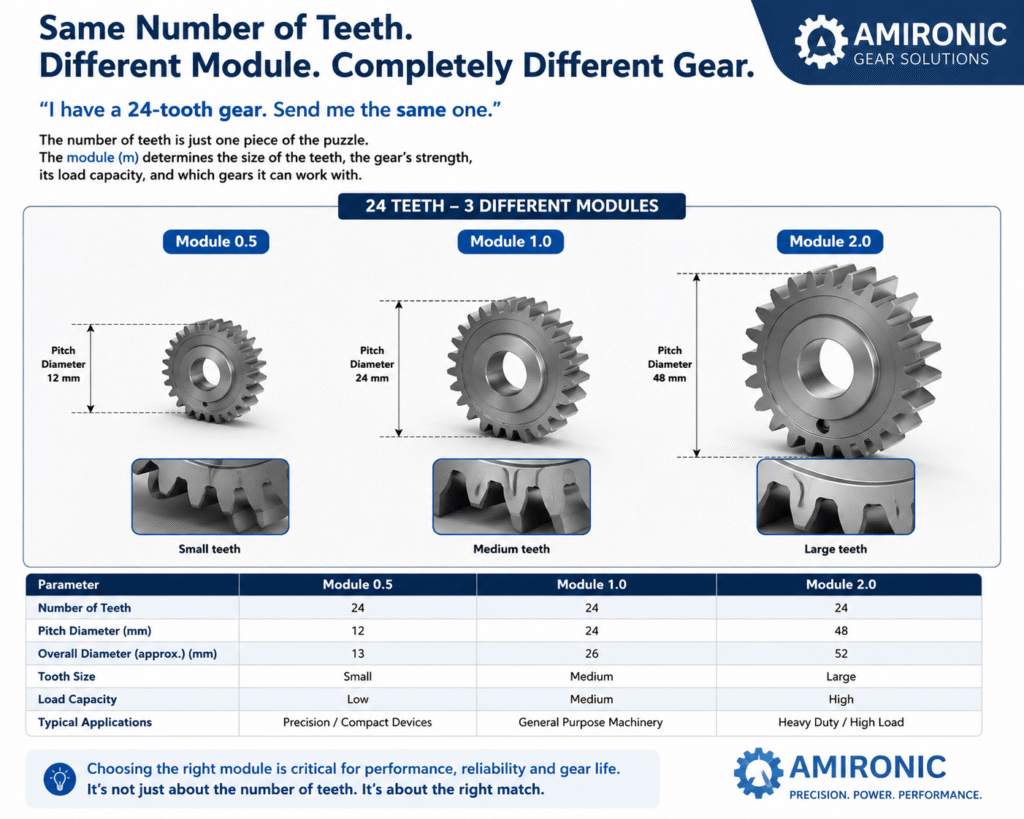
Figure 1: Three gears with the same 24 teeth, but different modules. As the module increases, the teeth become larger and stronger, the gear diameter increases, and the gear can transmit higher torque. This is why the number of teeth alone is not enough to select a replacement gear.

What Is Gear Module?

You can think of the gear module as the scale that defines the size of the gear teeth.

As the module increases, each tooth becomes larger, thicker, and deeper. As a result, the overall gear diameter increases, allowing the gear to transmit higher loads and greater torque.

Conversely, a smaller module produces finer teeth, making it possible to design more compact and precise gear systems. The tradeoff is a lower load-carrying capacity.

This is why two gears with the same number of teeth can differ dramatically in both size and performance simply because they were designed with different modules.

For example, a 24-tooth gear with a module of 0.5 is significantly smaller than a 24-tooth gear with a module of 2. Although both gears have the same number of teeth, they cannot mesh with each other and are intended for completely different applications.

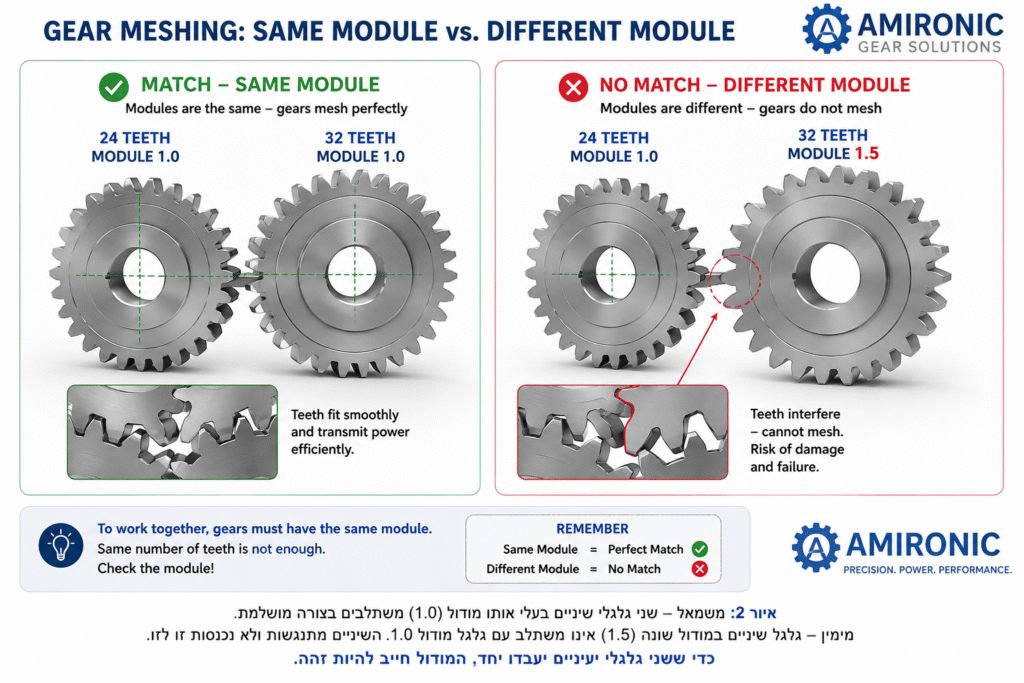
Can Gears with Different Modules Mesh Together?

The answer is simple: No.

For two gears to mesh correctly, they must have exactly the same module. Even if they have the same number of teeth, similar diameters, identical face widths, or are manufactured from the same material, a difference in module changes both the tooth size and the spacing between the teeth.

As a result, the teeth will not mesh properly, leading to excessive wear, noise, poor power transmission, and eventually mechanical failure.

This is one of the main reasons why the number of teeth alone is never enough to identify or replace a gear.

Figure 2: Two gears can mesh correctly only if they have the same module. The number of teeth alone does not determine compatibility – the module is the critical parameter.

How Do You Choose the Right Gear Module?

If the module determines the size of the gear teeth, the obvious question is:

Why not always choose a larger module?

The answer is that every gear design involves engineering tradeoffs.

A larger module increases tooth strength and torque capacity, but it also increases the gear diameter, weight, rotational inertia, and the space required by the transmission system.

On the other hand, a smaller module makes it possible to design compact, lightweight, and highly precise mechanisms. The tradeoff is a lower load-carrying capacity because the teeth are smaller.

For this reason, there is no universal rule for selecting a gear module. The optimal choice always depends on the requirements of the application.

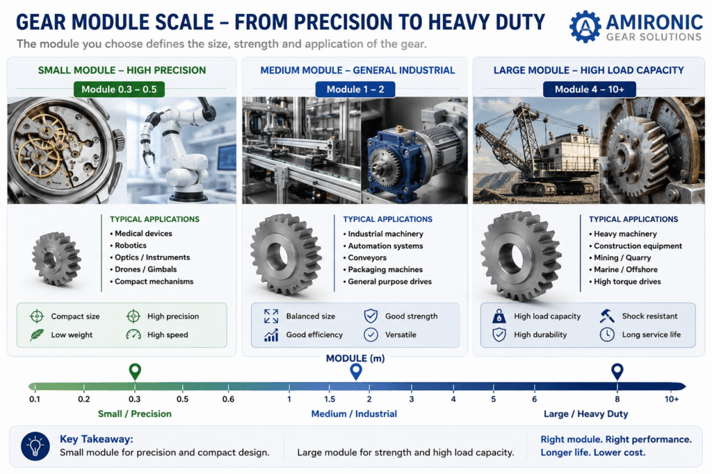
Small Module Large Module
Compact gear design Larger and stronger teeth
Lower weight Higher torque capacity
Higher precision Better resistance to shock loads
Suitable for high-speed applications Suitable for heavy-duty applications
Ideal where installation space is limited Ideal for harsh operating environments

Typical Applications by Module Size

Although there is no standard that specifies which module must be used for a particular application, certain ranges have become common in the industry.

Typical Module Common Applications
0.2 – 0.5 Medical devices, robotics, optics, precision instruments
0.6 – 1.0 Industrial automation, compact machinery, electronic equipment
1 – 2 General industrial machinery, conveyors, power transmission systems
2 – 4 Heavy industrial equipment, packaging machines, agricultural machinery
5 and above Mining equipment, cranes, heavy-duty drives, marine applications

These ranges should be considered general guidelines rather than strict rules. It is not uncommon to find compact systems using relatively large modules for increased durability, or large machines using smaller modules to achieve higher precision or satisfy specific design constraints.

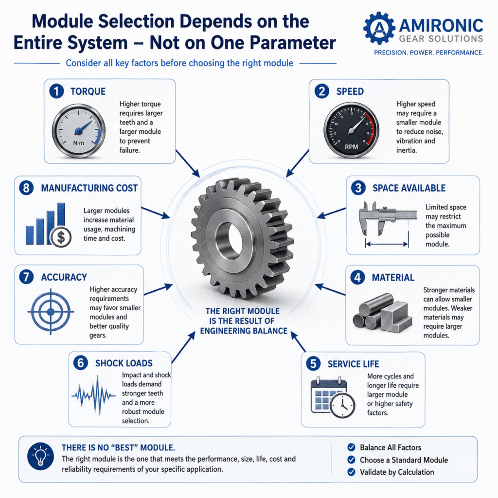
In practice, the gear module is selected only after considering factors such as transmitted torque, rotational speed, required service life, gear material, face width, operating environment, and the required safety factor.

Figure 3: There is no “best” or “correct” gear module. The appropriate module is determined by the application’s design requirements. Smaller modules are commonly used in compact, high-precision systems such as medical devices, robotics, and optical equipment, while larger modules are designed for higher torque transmission and heavy-duty applications, including industrial machinery, mining equipment, cranes, and marine systems.

How Do Engineers Select the Right Gear Module?

Contrary to popular belief, engineers do not select a gear module by simply looking it up in a table.

The process begins with the mechanical requirements of the application.

Typical design questions include:

  • How much torque must the gear transmit?
  • What is the required service life?
  • Will the system experience shock or impact loads?
  • What is the operating speed?
  • How much installation space is available?
  • Which gear material will be used?
  • Are there weight or rotational inertia limitations?
  • What level of positioning accuracy is required?

Only after these requirements have been defined can the engineer calculate the required tooth size and select the most appropriate standard module.

In other words, the gear module is the result of the design process, not its starting point.

Is a Larger Module Always Better?

The answer is no.

A larger module generally provides stronger teeth and higher torque capacity, but it also increases the gear diameter, weight, rotational inertia, and manufacturing cost.

In many applications, a smaller module is actually the better engineering choice because it enables a more compact, lighter, faster, and more precise transmission system.

The goal is not to choose the largest possible module, but to find the optimal balance between strength, size, precision, weight, cost, and service life.

Figure 4: The gear module is the result of an engineering design process, not its starting point. Selecting the appropriate module requires balancing torque capacity, operating speed, space constraints, strength, service life, precision, and cost. There is no universally “best” module – only the one that best fits the application’s requirements.

Gear Module Is Not the Only Factor That Determines Gear Strength

When higher torque capacity is required, many people assume that the solution is simply to select a larger gear module.

In reality, engineers have several ways to increase the strength of a gear system, and increasing the module is not always the best option.

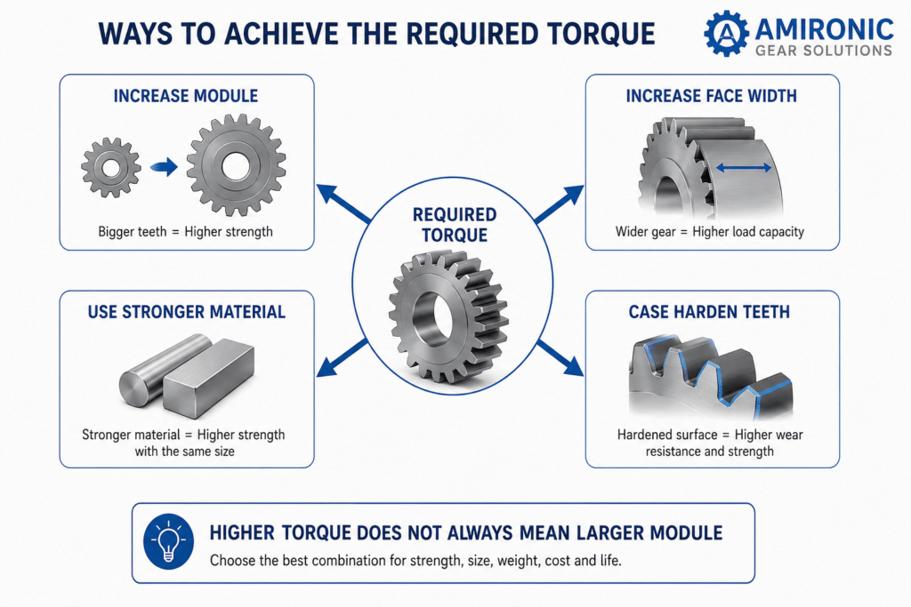
Depending on the application, they may choose to:

  • Increase the face width.
  • Use a stronger gear material.
  • Apply case hardening or another heat treatment.
  • Improve manufacturing quality and gear accuracy.
  • Adjust the required safety factor based on the operating conditions.

As a result, two gear systems transmitting exactly the same torque may use completely different modules.

For example, a robotic system with limited installation space may retain a relatively small module while using hardened steel and a wider face width to achieve the required strength. In contrast, an industrial machine with fewer space constraints may use a larger module because it simplifies manufacturing and provides excellent long-term durability.

This is precisely why a gear cannot be selected based solely on its number of teeth or even its module. Every gear system is the result of balancing multiple engineering requirements.

A Common Mistake: “Let’s Increase the Module”

Increasing the module certainly produces stronger gear teeth, but it is not a universal solution.

A larger module also increases:

  • Gear diameter
  • Center distance
  • System weight
  • Rotational inertia
  • Material and manufacturing costs

In many cases, increasing the face width or selecting a stronger material can deliver the required performance without redesigning the entire transmission system.

For this reason, experienced gear designers aim to select the smallest module that safely meets the application’s performance requirements, while maintaining the required safety factor and service life.

Figure 5: Increasing the gear module is only one way to improve torque capacity. In many applications, the required strength can also be achieved by increasing the face width, selecting a stronger material, or applying case hardening, while maintaining a more compact and lightweight gear system.

How Can You Identify the Module of an Existing Gear?

If you have the original gear, it is often possible to estimate its module even without the manufacturer’s drawing.

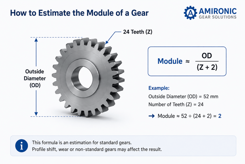
The simplest method is to measure the outside diameter (OD) and count the number of teeth.

For standard spur gears, the module can be estimated using the following equation:

Module ≈ Outside Diameter ÷ (Number of Teeth + 2)

Example

  • Outside Diameter (OD): 52 mm
  • Number of Teeth (Z): 24

Module ≈ 52 ÷ (24 + 2) = 2

It is important to remember that this is only an approximation. Gears with profile shift, worn teeth, or special designs may not follow this relationship accurately.

In such cases, additional measurements or the original manufacturer’s drawing are required to identify the correct module.

What Information Should You Send to Your Gear Supplier?

To identify an existing gear or manufacture an accurate replacement, provide as much of the following information as possible:

  • Gear module
  • Number of teeth
  • Pressure angle
  • Face width
  • Bore diameter
  • Gear material
  • Heat treatment requirements (if applicable)
  • Drawing or photographs, if available

The more complete the information, the easier it is to determine whether the gear is a standard catalog item or a custom-designed component.

Figure 6: When the original manufacturer’s drawing is unavailable, the gear module can be estimated by measuring the outside diameter (OD) and counting the number of teeth (Z). This equation provides a good approximation for standard spur gears and should be used as an initial estimate only. Gears with profile shift, worn teeth, or custom designs may require additional measurements or the original manufacturer’s specifications for accurate identification.

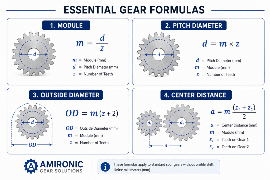
Figure 7: Basic equations for calculating gear module, pitch diameter, outside diameter, and center distance for standard spur gears. These equations apply to gears without profile shift, with all dimensions expressed in millimeters.

Conclusion

Although the number of teeth is often the first specification people look at, it is not enough to identify or select the correct gear.

The gear module is one of the most important parameters in gear design. It determines tooth size, gear diameter, torque capacity, service life, and whether two gears can mesh correctly.

Selecting the appropriate module is not based on a simple rule of thumb. Instead, it is the result of an engineering design process that considers load, speed, material, available space, service life, manufacturing cost, and the specific requirements of the application.

Ultimately, there is no universally “better” or “stronger” module. There is only the module that provides the best balance of performance, durability, size, and cost for a given application.


Common Mistakes

Mistake #1 – “If two gears have the same number of teeth, they are identical.”

Not true. Two gears may have exactly the same number of teeth but different modules, making them completely incompatible.

Mistake #2 – “A larger module is always better.”

Not necessarily. While a larger module increases tooth strength, it also increases gear size, weight, rotational inertia, and manufacturing cost.

Mistake #3 – “If the gear isn’t strong enough, just increase the module.”

A larger module is only one possible solution. In many cases, increasing the face width, selecting a stronger material, or applying an appropriate heat treatment can achieve the required performance without increasing the module.

Mistake #4 – “You can identify a gear simply by measuring its diameter.”

Incorrect. Different gears can have very similar outside diameters while having different modules and completely different tooth geometry.

Mistake #5 – “Any gears with the same module will mesh together.”

Not always. In addition to having the same module, the gears must also have compatible pressure angles, tooth profiles, face widths, and other design parameters.

Further Reading

For a broader understanding of motion transfer system design and the role of gears and couplings in overall system behavior, the following articles provide additional engineering insights:

  • Gears & Couplings: An Engineering Guide to Precision Motion Transfer

  • How to Choose the Right Coupling Without Guessing

  • Common Coupling Failures and How to Prevent Them

  • Gear Material Selection Guide: Strength, Wear, Corrosion & Environment – How to Choose Correctly

  • Backlash Is Not a Number: Understanding What Really Determines Accuracy, Stability, and System Life

  • Spur, Helical and Worm Gears – Engineering Differences and How to Choose the Right One

  • Backlash in Gears – From Geometry to System Behavior: Understanding what really happens between gear teeth
  • Small Spur Gears: Why Miniaturization Creates Hidden Mechanical Problems
  • Gear Hardening Explained – Why Case Hardened Gears Dominate Heavy Duty Power Transmission
  • Why a Million-Dollar Medical System Still Uses Rack & Pinion
  • Why Most Engineers Use Bevel Gears for Only 10% of What They Can Actually Do
  • Why the Number of Starts in a Worm Gear Matters More Than the Gear Ratio
  • The Gearbox Isn’t the Problem – It’s Simply the First to Pay for Design Mistakes
  • When the System Starts to Vibrate – Don’t Rush to Retune the Motion Controller
  • How to Calculate Gear Ratio and Choose the Right Gears

Frequently Asked Questions (FAQ)

Can two gears with the same number of teeth always mesh together?

No. At a minimum, they must have the same module, pressure angle, and tooth profile. If any of these parameters differ, the gears will not mesh correctly.

Can gears with different modules mesh together?

No. Gears with different modules are not compatible because their tooth size and spacing are different.

Does a larger module always provide higher torque capacity?

Generally, yes. Larger modules have larger and stronger teeth, allowing them to transmit higher loads. However, torque capacity also depends on factors such as face width, gear material, heat treatment, and overall gear geometry.

Can the module of an existing gear be calculated?

Yes. For standard spur gears, the module can be estimated from the outside diameter (OD) and the number of teeth (Z). For accurate identification, especially for custom or profile-shifted gears, additional measurements or the original manufacturer’s drawing are recommended.

What is the most common gear module?

There is no universal module. The appropriate module depends entirely on the application. Precision and compact systems typically use smaller modules, while heavy industrial machinery and high-load applications generally require larger modules.


Key Terms

Module – The primary gear parameter that defines tooth size and determines whether two gears can mesh correctly.

Pitch Diameter – The theoretical diameter at which two meshing gears roll together without slipping.

Outside Diameter (OD) – The overall outside diameter of the gear.

Number of Teeth (Z) – The total number of teeth on the gear.

Pressure Angle – The angle at which force is transmitted between mating gear teeth.

Face Width – The width of the gear teeth measured parallel to the gear axis. A wider face generally increases load-carrying capacity.

Profile Shift – A controlled modification of the standard tooth geometry used to improve strength, prevent undercutting, or adjust the center distance.

Case Hardening – A heat treatment process that hardens the surface of the gear teeth while maintaining a tougher, more ductile core.

Backlash – The intentional clearance between mating gear teeth, allowing smooth operation, lubrication, thermal expansion, and manufacturing tolerances.

Tags: Amironic

Related Articles

How to Select Microelectronics Packaging for Harsh Environments

26/04/2026amironicLTD

The Silent Problem of Precision Systems – Why Gyros and IMUs Are Control Components, Not Just Sensors

01/02/2026amironicLTD

Bridging Control and Navigation: How Advanced MEMS IMUs Are Redefining System Performance

15/02/2026amironicLTD

Recent Posts

  • “I Have a 24-Tooth Gear. Send Me the Same One.”
  • Your PT100 Sensor Isn’t Reading the Wrong Temperature – Your Wiring Might Be
  • When GPS Lies: Why IMUs Are Becoming Mission-Critical in the Era of Autonomous Wingmen
  • Why Wireless Footswitches Are Becoming the Standard in Mobile Medical Equipment
  • Why a Dual-Channel Rotary Position Sensor Is Not Just a Backup Sensor

Categories

  • Air Switch
  • Circuit Breakers
  • Elapsed Time Indicator
  • Feedthrough
  • Footswitches
  • Gears & Transmission
  • Hour Meters
  • Infra Red Switches
  • INFRARED LAMPS
  • Low Noise Inertial MEMS
  • Mechanics
  • MEMS Gyroscope
  • MEMS Inertial
  • Microelectronics
  • Motors
  • Position Sensors
  • Power Supply
  • Pressure Sensors
  • Pressure Switch
  • Temperature Sensors
  • Tungsten and Molybdenum
  • Uncategorized
  • Vacuum Switches

Quick Contact

Fill out the form and our representatives will return to you

    Name (required)

    Email (required)

    Phone

    Message

    This site is protected by reCAPTCHA and the Google
    Privacy Policy and
    Terms of Service apply.

    Amironic Ltd.

    3 Rabinovich Street, Petah Tikva 4928144 , Israel. Tel: +972-3-9047744 E-mail: office@amironic.co.il
    Email
    Facebook
    Twitter
    LinkedIn
    YouTube
    Press on the ISO Certificate below for download
    ISO 9001:2015 Certification
    • MEMS Inertial
    • Circuit Breakers
    • Footswitches
    • Mechanical & Transmisions
    • Sensors
    • Motors
    • Electronics
    • Hand Control
    • Power Solutions

    News

    • “I Have a 24-Tooth Gear. Send Me the Same One.”
    • Your PT100 Sensor Isn’t Reading the Wrong Temperature – Your Wiring Might Be
    • When GPS Lies: Why IMUs Are Becoming Mission-Critical in the Era of Autonomous Wingmen
    • Why Wireless Footswitches Are Becoming the Standard in Mobile Medical Equipment
    • Why a Dual-Channel Rotary Position Sensor Is Not Just a Backup Sensor
    About AmironicContactעברית
    © 2022 Amironic All rights reserved. All Trademarks are the property of their respective owners.
    • Increase Font
    • Decrease Font
    • Black & White
    • Inverse Colors
    • Highlight Links
    • Regular Font
    • Reset