flagעברית
flagEnglish
3 Rabinovich St., Petah-Tikva, Israel
+972 3 9047744
office@amironic.co.il
Facebook
Twitter
LinkedIn
YouTube
  • Products
    • MEMS Inertial
      • Gyros & Accels
      • IMU
      • Inertial Navigation
      • AHRS
    • Circuit Breakers
      • Airpax Circuit Breakers
      • Electronic Circuit Breakers
      • Aircraft Circuit Breakers
      • Thermal Circuit Breakers
      • Sealing Solutions & Guards
    • Footswitches
      • Pedals & Bellows
      • USB
      • Air Switches
      • Medical
      • Modular Bases System
      • Industrial
      • Foot Potentiometers
      • Wireless
    • Mechanical & Transmisions
      • Gears
      • Sealing Solutions
      • Gearboxes
      • Couplings
      • Shafts & Bearings
      • Fasteners
      • Mechanical & Springs
      • Linear Motion
      • Anti-Vibration
    • Sensors
      • Thermostats
      • Temperature
      • Position
      • Pressure
      • Speed
      • Level Sensor
      • Load Cells
      • Flex Sensors
      • Membrane Potentiometer
    • Motors
      • Geared DC
      • Brushless DC
      • Step Motors with Gearbox
      • Torque Motors & Brushless Servo
      • DC Motors
    • Electronics
      • Xenon & IR Lamps
      • Counters & Meters
      • Microelectronics Packaging
      • Waterproof Switches
      • Micro Switches
    • Hand Control
      • Operator Controls (JOYSTICK)
      • Electrical
      • Pneumatic (Medical)
      • USB Hand Control
      • Air Push Button
      • Pressure Switch
      • IR Switch
    • Power Solutions
      • Rugged & Military Power Supply
      • Input Power Protection
      • Sealed Military Power Adaptor
      • Triple Output Military Power Supply Series – up to 250 W
    • Materials
      • Molybdenum and Advanced Alloys (TZM, MOLA, HCT)
      • Tungsten (Wolfram) and Advanced Alloys – High-Performance Materials for Extreme Conditions
      • Materials for Gears
  • Shop
  • Companies
  • About Amironic
  • News
  • Contact
Product was added to your cart

Cart

waze

5 mm Shaft & Bearing – Worm Gear Fits and Tolerances

Mechanics11/10/2026amironicLTD
A difference of just 0.05 mm can turn a seemingly simple mechanical assembly into an engineering challenge. When designing a worm and worm wheel transmission (Worm & Worm Wheel), selecting the correct module, gear ratio, and materials is not enough. The fits between shafts, bores, and bearings must also be precisely defined.

The Problem: When a Solution Intended to Eliminate Mechanical Play Creates a New Problem

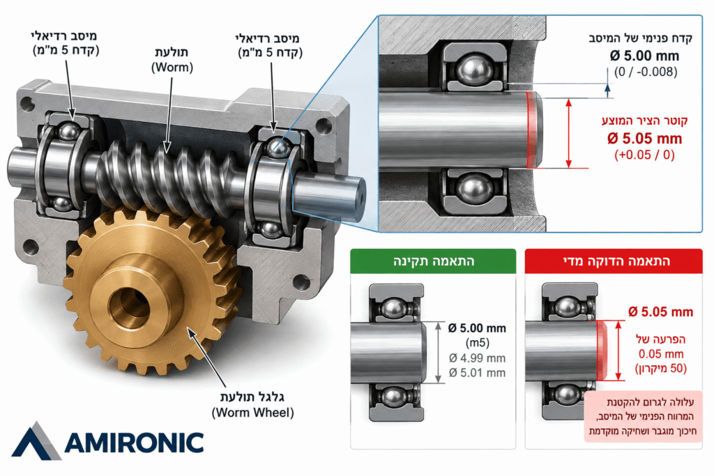
Consider an engineer designing a compact motion mechanism based on a worm and worm wheel transmission. The system includes two shafts supported by radial bearings with nominal inner diameters of 4 mm and 5 mm.

To ensure that the bearings remain securely mounted and do not slip on the shafts, the engineer decides to increase the shaft diameters to 4.05 mm and 5.05 mm, respectively.

At first glance, the reasoning seems straightforward: if the shaft is slightly larger than the bearing bore, an interference fit will be created, keeping the bearing firmly in place.

However, this is precisely where the problem begins.

A nominal difference of 0.05 mm may sound insignificant, but in a small bearing, it represents 50 microns. Such an interference can be substantially greater than the permissible interference for bearing installation.

When the bearing’s inner ring is pressed onto an oversized shaft, it may expand, reducing the bearing’s internal clearance. The potential consequences include increased friction, overheating, premature wear, and even bearing damage during assembly.

The problem is not necessarily the use of an interference fit, but rather selecting the amount of interference without considering manufacturing tolerances, bearing type, and the manufacturer’s recommendations.

The engineering takeaway: A tighter fit is not necessarily a better fit.
The Solution Begins by Distinguishing Between Three Assembly Interfaces

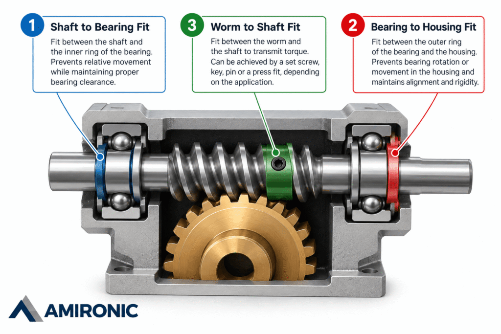
One of the common mistakes in mechanical assembly design is treating all bores and shafts as if they require the same type of fit. In practice, a worm and worm wheel transmission (Worm & Worm Wheel) involves three distinct assembly interfaces, each serving a different mechanical purpose.

1. Shaft to Bearing Fit

The bearing allows the shaft to rotate while supporting the loads acting on it. The fit between the shaft and the bearing’s inner ring must prevent unwanted relative movement while preserving the internal clearance required for proper bearing operation.

2. Bearing to Housing Fit

The bearing’s outer ring also requires an appropriate fit within its housing. An incorrect fit may cause bearing movement, deformation of the outer ring, or difficulties during assembly and disassembly.

3. Worm/Wheel to Shaft Fit

Here, the objective is different: to ensure reliable torque transmission between the gear component and the shaft. Depending on the system requirements, this can be achieved using a set screw, pin, keyway, or a properly engineered interference fit.

This means that a tolerance suitable for the bore of a worm wheel is not necessarily appropriate for the shaft diameter at the bearing mounting location.

What Do H8, h6, k6, and m6 Mean?

Manufacturing tolerances defined by the ISO system specify the permissible range of dimensions around a nominal diameter.

The letter indicates the position of the tolerance zone relative to the nominal dimension, while the number indicates the tolerance grade. Uppercase letters are used for holes and bores, while lowercase letters are used for shafts.

Designation Meaning Possible Application
H8 Bore tolerance with zero lower deviation Bores in worms and worm wheels
h6 Shaft tolerance with zero upper deviation Shafts requiring precise dimensional control
k6 Shaft tolerance zone with a tendency toward positive deviation Transition or interference fits, depending on the mating bore
m6 Shaft tolerance zone positioned further above the nominal dimension Tighter fits, depending on the mating bore

It is important to understand that the H8 designation alone does not define an interference fit or a clearance fit. The actual fit is determined by the combination of the bore tolerance and the shaft tolerance.

For example, a nominal 5 mm bore with an H8 tolerance has a permissible diameter range of 5.000 to 5.018 mm according to ISO 286.

If the shaft is manufactured with a diameter of 5.05 mm, it will be 0.032 mm larger than even the maximum permissible bore diameter in this example. This represents significant interference and should not be approved without evaluating the mechanical design and assembly method.

However, when dealing with a radial bearing, the H8 tolerance specified for a worm gear bore must not be used to calculate the bearing fit. Bearings have their own manufacturing tolerances, and the fit must be determined using the technical specifications of the particular bearing.

Why Are H8 Bores Used in Worms and Worm Wheels?

In small mechanical transmissions, H8 bores are one of the commonly used options for manufacturing components intended to be mounted on separate shafts.

This tolerance provides a controlled dimensional range for the bore, allowing the engineer to select the appropriate shaft tolerance and fastening method according to the system requirements.

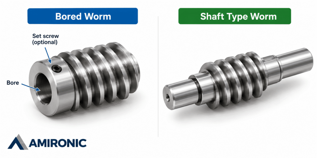
For example, a bored worm with a nominal 5 mm bore can be mounted on a suitably designed shaft, using a set screw or another mechanical fastening method to transmit torque.

In other cases, a shaft type worm may be selected, where the worm and shaft are manufactured as a single integral component. This eliminates the need for a separate connection between the worm and the shaft.

When a special bore diameter is requested, it is important to determine whether the dimensional modification is truly necessary or whether the same objective can be achieved by adjusting the shaft tolerance or selecting a different fastening method.

Making the right choice during the design stage can eliminate unnecessary custom manufacturing, reduce costs, and simplify assembly.

What About the Loads Acting on the Bearing?

In a worm and worm wheel transmission, the interaction between the gear teeth generates forces in multiple directions. In addition to radial loads, axial loads are also generated, particularly on the worm shaft.

Therefore, selecting a bearing involves much more than choosing its inner diameter.

Engineers must consider the direction and magnitude of the loads, rotational speed, shaft stiffness, bearing support arrangement, and the bearing’s ability to withstand combined loads.

The shaft fit is also influenced by the loading conditions. When the bearing’s inner ring rotates relative to the direction of the applied load, a tighter fit may be required compared with a situation where the load direction remains stationary relative to the ring.

Radial bearing fit tables provide recommended shaft tolerances based on shaft diameter, bearing type, and loading conditions. However, the final selection must always be based on the specifications of the particular bearing and the application’s operating requirements.

The engineering conclusion is straightforward: Do not start by increasing the shaft diameter to achieve a tighter grip. Start with the loads, bearing type, and mounting method, and only then define the appropriate tolerances.

Press Fit, Set Screw, or Keyway – How Do You Choose the Right Shaft Fastening Method?

Once the shaft and bore diameters have been defined, another important question arises: How can we ensure that the worm or worm wheel transmits torque to the shaft without slipping, loosening, or compromising motion accuracy?

The answer depends on the transmitted torque, load direction, frequency of direction changes, and maintenance requirements of the system.

Press Fit (Interference Fit)

In a press fit, the shaft diameter is intentionally made slightly larger than the bore diameter. During assembly, contact pressure develops between the mating surfaces, allowing torque to be transmitted through friction.

The main advantage is a compact connection without requiring an additional screw or pin. The disadvantage is its sensitivity to manufacturing tolerances and assembly forces.

An excessively tight interference fit may deform or damage the component, while insufficient interference may allow slipping under load.

Therefore, the required interference must be calculated based on the component materials, diameters, contact length, and torque to be transmitted.

Set Screw

A set screw is a common fastening solution for bored worms. The screw is tightened against the shaft, preventing relative movement through clamping force and, in some cases, localized engagement with the shaft surface.

Its main advantage is straightforward assembly, with the possibility of disassembly and adjustment. However, in systems exposed to vibration, cyclic loading, or frequent changes in rotational direction, the connection must be evaluated for resistance to loosening.

Key and Keyway

A keyed connection allows torque to be transmitted through mechanical contact between the shaft, key, and gear hub rather than relying solely on friction.

This solution is useful when significant torque must be transmitted or when reducing dependence on clamping force is desirable.

However, the keyway reduces the effective cross-sectional area of the shaft and introduces stress concentrations. Shaft dimensions, applied loads, and operating conditions must therefore be considered.

Cross Pin

A pin passing through both the shaft and the transmission component can provide a relatively simple mechanical connection.

This solution is suitable for certain applications, but requires evaluation of shear stresses, local bearing stresses, and the effect of the transverse hole on shaft strength.

Comparison of Shaft Fastening Methods

Fastening Method Main Advantage Design Consideration
Press Fit Compact connection without additional components Sensitive to tolerances and assembly forces
Set Screw Simple assembly and disassembly Risk of loosening or slipping under variable loads
Key and Keyway Torque transmission through mechanical engagement Stress concentration in the shaft
Cross Pin Direct mechanical fastening Reduced shaft cross-section and stresses in the pin

No single fastening method is suitable for every application. The correct choice should be based on the system’s mechanical requirements rather than manufacturing convenience alone.

When Is an Integral Shaft Worm the Better Choice?

In a bored worm, the worm is manufactured with a bore and mounted onto a separate shaft. In contrast, a shaft type worm is manufactured as a single integral component, combining the worm and shaft.

This distinction can be particularly important in compact mechanical systems.

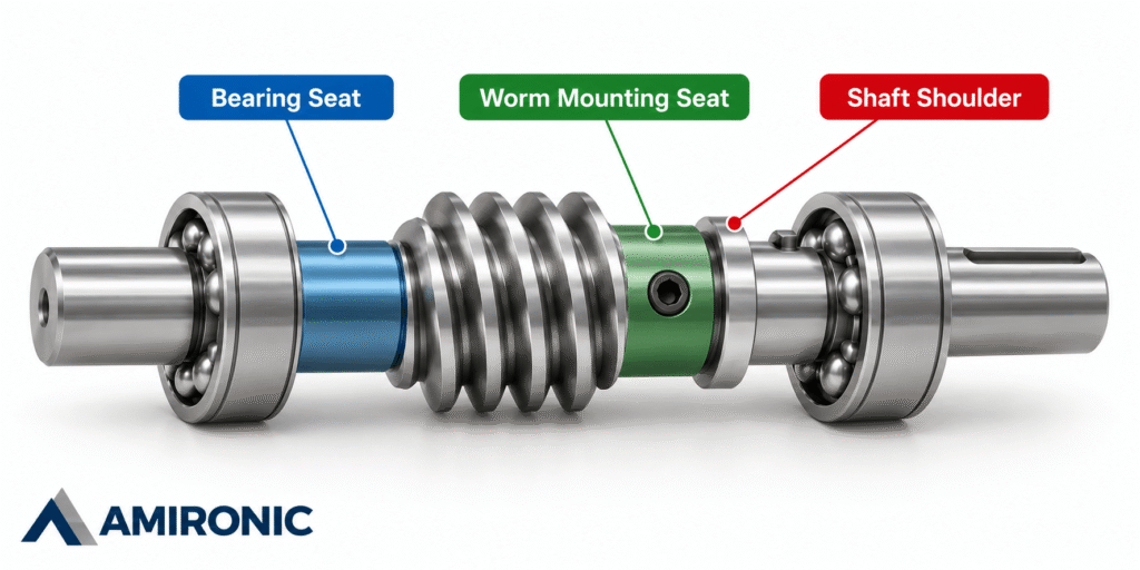
An integral shaft worm eliminates the need for a separate connection between the worm and the shaft. It also allows the bearing seats, shaft shoulders, and different shaft diameters to be designed as part of a single component.

This can reduce potential sources of mechanical play, concentricity errors, and relative movement between the worm and shaft.

However, an integral design may offer less flexibility when replacing individual components, making modifications during development, or manufacturing special geometries.

When using a bored worm, the bore tolerance, shaft tolerance, and torque transmission method must be specified separately.

Why Can Even a Precisely Manufactured Assembly Fail?

Even when every component has been manufactured according to its drawing, the assembled mechanism may still experience excessive friction, vibration, or premature wear.

One possible reason is tolerance stack-up.

Every component in the system has an allowable dimensional variation, including the shaft diameter, worm bore, bearing locations, bearing housing dimensions, and center distance between the shafts.

When these variations accumulate, they can affect component alignment and the contact conditions between the worm and worm wheel teeth.

For example, a positional deviation in the bearing housings may shift the worm shaft relative to the worm wheel.

Even when the gear ratio and module are correct, changes in center distance or shaft alignment can affect tooth load distribution, noise, and wear.

Therefore, verifying the fit should not end with measuring the shaft and bore diameters.

Engineers must also examine concentricity, shaft shoulder positions, bearing alignment, and the center distance between the transmission shafts.

The key principle is that a correctly toleranced individual component does not guarantee a properly functioning assembly. The entire system’s tolerance stack-up must be evaluated.

Before Ordering: Seven Checks That Can Prevent Assembly Failure

Even when the worm and worm wheel have been correctly selected in terms of module, gear ratio, and materials, small mistakes in shaft and bore specifications may only become apparent during assembly.

Before releasing a drawing for manufacturing or ordering components, several essential checks should be performed.

1. Is the Shaft Diameter Specified with a Tolerance?

Specifying only a nominal diameter, such as Ø5 mm, is not sufficient when a precise fit is required. The permissible dimensional range must be defined according to the shaft’s function and the component mounted on it.

2. Is the Bore Tolerance Compatible with the Shaft Tolerance?

Both tolerance ranges must be evaluated to calculate the possible clearance or interference under worst-case dimensional conditions. A fit that appears acceptable based on nominal dimensions may actually be too tight or too loose.

3. Has the Bearing Fit Been Selected According to Operating Conditions?

A matching inner diameter does not guarantee proper bearing operation. Radial and axial loads, rotational speed, internal bearing clearance, and temperature variations must all be considered.

4. How Is Torque Transmitted Between the Worm and the Shaft?

When using a bored worm, the fastening method must be specified. Set screws, pins, keys, and interference fits are not interchangeable solutions, and each has its own mechanical limitations.

5. Have Concentricity and Alignment Been Verified?

Even when shaft and bore diameters are within tolerance, concentricity errors or misalignment between bearings can introduce unwanted loads, vibration, and wear.

6. Has Tolerance Stack-Up Been Considered?

The combined effects of dimensional variations in shafts, bearing housings, and transmission components must be evaluated to determine their influence on shaft positioning and gear tooth contact conditions.

7. Can the Assembly Be Installed and Disassembled Properly?

Good mechanical design must also account for the assembly process. There should be adequate access for assembly tools, pressing forces must not be transmitted through the bearing’s rolling elements, and maintenance or component replacement should remain practical.

Practical Example: How Should a 5 mm Shaft Be Designed?

Let us return to the example of installing a bearing with a nominal inner diameter of 5 mm onto a shaft.

Instead of automatically specifying a 5.05 mm shaft diameter to create an interference fit, the process should begin with selecting the bearing and reviewing its technical specifications.

The next step is to identify the operating loads, determine whether a tight fit between the inner ring and the shaft is required, and select the appropriate shaft tolerance according to the relevant technical recommendations.

Separately, the bore of the worm or worm wheel and its shaft fastening method must be defined.

If a transmission component with an H8 bore is selected, the fit between that bore and the corresponding shaft section must be evaluated. A tolerance suitable for mounting the bearing should not automatically be assumed suitable for mounting the worm.

In some applications, a stepped shaft can be used, with different diameter sections designed for specific functions: one section for the bearing seat, another for mounting the worm, and an additional shoulder or fastening feature for axial positioning.

This approach allows each interface to be designed independently, without compromising assembly requirements or torque transmission capability.

The solution is not necessarily to modify the transmission component or increase the shaft diameter, but to properly engineer the interfaces between the components.

Conclusion: True Precision Lies in the Connections Between Components

When designing a worm and worm wheel transmission (Worm & Worm Wheel), it is easy to focus on selecting the correct module, gear ratio, and materials. However, even when all these parameters are appropriate, the system may still fail because of an incorrect fit between the shaft, bore, and bearing.

A difference of just 0.05 mm, which may appear insignificant on a technical drawing, can have a major impact on a compact mechanical assembly.

Proper design therefore requires careful consideration of manufacturing tolerances, operating loads, fastening methods, bearing locations, and the cumulative effects of dimensional variations.

The correct engineering approach is to define the mechanical requirements of each interface first, and only then select the appropriate dimensions and tolerances.

Designing a Worm and Worm Wheel Transmission?

Amironic offers a wide range of mechanical transmission solutions, including worms, worm wheels, gears, and motion transmission components.

Contact us with your technical drawing, specifications, or mechanical requirements to explore standard components and application-specific solutions.

Amironic – Engineered Solutions for Precision Motion Transmission.

Further Reading

For a broader understanding of motion transfer system design and the role of gears and couplings in overall system behavior, the following articles provide additional engineering insights:

  • Gears & Couplings: An Engineering Guide to Precision Motion Transfer

  • How to Choose the Right Coupling Without Guessing

  • Common Coupling Failures and How to Prevent Them

  • Gear Material Selection Guide: Strength, Wear, Corrosion & Environment – How to Choose Correctly

  • Backlash Is Not a Number: Understanding What Really Determines Accuracy, Stability, and System Life

  • Spur, Helical and Worm Gears – Engineering Differences and How to Choose the Right One

  • Backlash in Gears – From Geometry to System Behavior: Understanding what really happens between gear teeth
  • Small Spur Gears: Why Miniaturization Creates Hidden Mechanical Problems
  • Gear Hardening Explained – Why Case Hardened Gears Dominate Heavy Duty Power Transmission
  • Why a Million-Dollar Medical System Still Uses Rack & Pinion
  • Why Most Engineers Use Bevel Gears for Only 10% of What They Can Actually Do
  • Why the Number of Starts in a Worm Gear Matters More Than the Gear Ratio
  • The Gearbox Isn’t the Problem – It’s Simply the First to Pay for Design Mistakes
  • When the System Starts to Vibrate – Don’t Rush to Retune the Motion Controller
  • How to Calculate Gear Ratio and Choose the Right Gears
  • “I Have a 24-Tooth Gear. Send Me the Same One.”
  • How to Identify an Existing Gear Without a Drawing – A Practical Measurement Guide for Engineers

Frequently Asked Questions (FAQs) – Worm Gears, Tolerances, and Fits

Is a 5.05 mm Shaft Suitable for a Bearing with a 5 mm Inner Diameter?

Not necessarily. A nominal difference of 0.05 mm creates significant interference in a small bearing, potentially reducing its internal clearance and causing increased friction and wear. The shaft tolerance must be selected according to the bearing type, operating loads, and recommended mounting specifications.

What Does an H8 Bore Tolerance Mean in a Worm Gear?

H8 is an ISO tolerance designation for holes and bores. For example, a nominal 5 mm bore with an H8 tolerance has a permissible diameter range of 5.000 to 5.018 mm. The actual fit depends on the tolerance of the mating shaft.

What Is the Difference Between a Press Fit and a Clearance Fit?

A press fit, also known as an interference fit, occurs when the shaft is larger than the mating bore, creating contact pressure between the components. A clearance fit provides a gap between the shaft and bore. The appropriate fit depends on the connection’s function, operating loads, and assembly requirements.

Can a Worm or Worm Wheel Be Mounted on a Shaft Without an Interference Fit?

Yes. A worm or worm wheel can be secured using a set screw, key and keyway, pin, or another mechanical fastening method. The selected connection must be capable of transmitting the required torque while maintaining the component’s position.

What Is the Difference Between a Bored Worm and a Shaft Type Worm?

A bored worm has a central bore and is designed to be mounted on a separate shaft. A shaft type worm is manufactured as a single integral component with its shaft. The choice depends on the assembly configuration, precision requirements, and maintenance or replacement considerations.

Does a Tighter Interference Fit Improve Bearing Reliability?

Not necessarily. Excessive interference may reduce the bearing’s internal clearance and negatively affect its operation. The required interference must be determined according to the application requirements and the bearing manufacturer’s recommendations.

Why Do Axial Loads Occur in Worm and Worm Wheel Transmissions?

The helical geometry of the worm generates forces with both radial and axial components during torque transmission. Therefore, the shaft support arrangement and bearings must be designed to withstand the expected loads.

What Is Tolerance Stack-Up?

Tolerance stack-up refers to the combined effect of permissible dimensional variations across multiple components in an assembly. In a worm and worm wheel transmission, these variations can affect shaft alignment, bearing positioning, and gear tooth contact.

Can Worms or Worm Wheels Be Ordered with Custom Bores?

Yes. Worm gear components can be manufactured with custom bores, threads, keyways, and other application-specific features, depending on manufacturing capabilities. Before specifying a non-standard bore, it is worth checking whether a standard component can be used by modifying the shaft design or fastening method.

Tags: Amironic

Related Articles

When the System Starts to Vibrate – Don’t Rush to Retune the Motion Controller

14/07/2026amironicLTD

Common Coupling Failures and How to Prevent Them

03/03/2026amironicLTD

Gear Hardening Explained – Why Case Hardened Gears Dominate Heavy Duty Power Transmission

26/05/2026amironicLTD

Recent Posts

  • 5 mm Shaft & Bearing – Worm Gear Fits and Tolerances
  • Filter Monitoring in Fume Extraction Systems – Detecting Filter Clogging with Pressure & Vacuum Switches
  • Pressure in HVAC/R Systems – More Than Protection, It’s a Control Variable
  • Heavy Duty Foot Controls for Specialty Vehicles – An Engineer’s Guide to Foot Control Interface Design
  • Switches and Controls for Special Purpose Vehicles – Heavy Duty Controls for Harsh Environments

Categories

  • Air Switch
  • Circuit Breakers
  • Elapsed Time Indicator
  • Feedthrough
  • Footswitches
  • Gears & Transmission
  • Hour Meters
  • Infra Red Switches
  • INFRARED LAMPS
  • Low Noise Inertial MEMS
  • Mechanics
  • MEMS Gyroscope
  • MEMS Inertial
  • Microelectronics
  • Motors
  • Position Sensors
  • Power Supply
  • Pressure Sensors
  • Pressure Switch
  • Switches
  • Temperature Sensors
  • Tungsten and Molybdenum
  • Uncategorized
  • Vacuum Switches

Quick Contact

Fill out the form and our representatives will return to you

    Name (required)

    Email (required)

    Phone

    Message

    This site is protected by reCAPTCHA and the Google
    Privacy Policy and
    Terms of Service apply.

    Amironic Ltd.

    3 Rabinovich Street, Petah Tikva 4928144 , Israel. Tel: +972-3-9047744 E-mail: office@amironic.co.il
    Email
    Facebook
    Twitter
    LinkedIn
    YouTube
    Press on the ISO Certificate below for download
    ISO 9001:2015 Certification
    • MEMS Inertial
    • Circuit Breakers
    • Footswitches
    • Mechanical & Transmisions
    • Sensors
    • Motors
    • Electronics
    • Hand Control
    • Power Solutions

    News

    • 5 mm Shaft & Bearing – Worm Gear Fits and Tolerances
    • Filter Monitoring in Fume Extraction Systems – Detecting Filter Clogging with Pressure & Vacuum Switches
    • Pressure in HVAC/R Systems – More Than Protection, It’s a Control Variable
    • Heavy Duty Foot Controls for Specialty Vehicles – An Engineer’s Guide to Foot Control Interface Design
    • Switches and Controls for Special Purpose Vehicles – Heavy Duty Controls for Harsh Environments
    About AmironicContactעברית
    © 2022 Amironic All rights reserved. All Trademarks are the property of their respective owners.
    • Increase Font
    • Decrease Font
    • Black & White
    • Inverse Colors
    • Highlight Links
    • Regular Font
    • Reset