flagעברית
flagEnglish
3 Rabinovich St., Petah-Tikva, Israel
+972 3 9047744
office@amironic.co.il
Facebook
Twitter
LinkedIn
YouTube
  • Products
    • MEMS Inertial
      • Gyros & Accels
      • IMU
      • Inertial Navigation
      • AHRS
    • Circuit Breakers
      • Airpax Circuit Breakers
      • Electronic Circuit Breakers
      • Aircraft Circuit Breakers
      • Thermal Circuit Breakers
      • Sealing Solutions & Guards
    • Footswitches
      • Pedals & Bellows
      • USB
      • Air Switches
      • Medical
      • Modular Bases System
      • Industrial
      • Foot Potentiometers
      • Wireless
    • Mechanical & Transmissions
      • Gears
      • Sealing Solutions
      • Gearboxes
      • Couplings
      • Shafts & Bearings
      • Fasteners
      • Mechanical & Springs
      • Linear Motion
      • Anti-Vibration
    • Sensors
      • Thermostats
      • Temperature
      • Position
      • Pressure
      • Speed
      • Level Sensor
      • Load Cells
      • Flex Sensors
      • Membrane Potentiometer
    • Motors
      • Geared DC
      • Brushless DC
      • Step Motors with Gearbox
      • Torque Motors & Brushless Servo
      • DC Motors
    • Electronics
      • Xenon & IR Lamps
      • Counters & Meters
      • Microelectronics Packaging
      • Waterproof Switches
      • Micro Switches
    • Hand Control
      • Operator Controls (JOYSTICK)
      • Electrical
      • Pneumatic (Medical)
      • USB Hand Control
      • Air Push Button
      • Pressure Switch
      • IR Switch
    • Power Solutions
      • Rugged & Military Power Supply
      • Input Power Protection
      • Sealed Military Power Adaptor
      • Triple Output Military Power Supply Series – up to 250 W
    • Materials
      • Molybdenum and Advanced Alloys (TZM, MOLA, HCT)
      • Tungsten (Wolfram) and Advanced Alloys – High-Performance Materials for Extreme Conditions
      • Materials for Gears
  • Shop
  • Companies
  • About Amironic
  • News
  • Contact
Product was added to your cart

Cart

waze

SX2 vs. SX3 – The Future of Inertial Sensor Technology

MEMS Inertial28/10/2026amironicLTD

The Next Generation of MEMS Sensors: Lower Noise, Higher Stability, and Improved Tactical Precision

In a world where military and civilian systems must operate at high speeds, under vibration, temperature fluctuations, and extreme environmental conditions, the quality of inertial measurements has become one of the most critical factors affecting overall system performance.

In electro-optical and infrared (EO/IR) stabilization systems, tracking systems, unmanned aerial vehicles (UAVs), and navigation systems operating in GPS-denied or GPS-degraded environments, even small measurement errors can affect stabilization accuracy, tracking performance, and the reliability of motion estimation.

Gladiator Technologies, a US-based company represented in Israel by Amironic Ltd., develops and manufactures gyroscopes, accelerometers, and Inertial Measurement Units (IMUs) based on advanced Silicon MEMS technology.

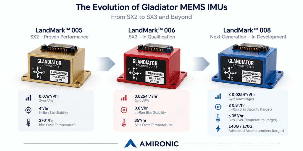
Following the success of the SX2 generation, including the G300D gyroscope and LandMark 005 IMU, the company is advancing its SX3 generation with the G400D gyroscope and LandMark 006 IMU, both undergoing qualification, alongside the development of the LandMark 008 IMU for next-generation high-dynamic applications.

The transition between generations goes beyond incremental improvements in resolution or sampling rates. It focuses on three key characteristics: reducing measurement noise, improving bias stability, and maintaining fast sensor response.

1. What Has Really Changed from SX2 to SX3?

The SX2 generation already offered a combination of low noise, compact dimensions, calibration over a wide temperature range, and high-speed signal processing through VELOX technology.

The SX3 generation is designed to improve the quality of the inertial measurements themselves, enabling control systems to receive cleaner, more stable data while maintaining high bandwidth and low latency.

Three key performance parameters illustrate this technological advancement:

Angle Random Walk – ARW

Angle Random Walk (ARW) describes the contribution of random gyroscope noise to accumulated angular error.

The lower the ARW value, the smaller the random error generated when integrating angular rate measurements to calculate changes in angle.

From an operational perspective, lower ARW enables more accurate estimation of small angular movements, particularly in precision stabilization systems and inertial navigation applications.

In-Run Bias Stability

In-Run Bias Stability describes the stability of the sensor’s measurement bias during operation.

Even when a system is stationary, a gyroscope may indicate a small non-zero angular rate. This offset is known as bias.

When the bias changes during operation, it can produce accumulated angular errors. Improved bias stability helps reduce the impact of these errors, particularly when continuous corrections from external sensors are unavailable.

Bias Over Temperature

Bias Over Temperature describes how the sensor’s bias changes across its operating temperature range, following the applicable calibration.

This parameter is particularly important in systems exposed to changing environmental conditions, such as unmanned aerial vehicles, outdoor surveillance platforms, and military systems operating across significant temperature variations.

A sensor with high thermal stability allows the system to maintain more consistent measurement performance as ambient temperatures change.

These three parameters complement one another. A sensor with low noise but unstable bias may deliver excellent short-term measurements while accumulating significant errors over longer operating periods.

2. Technology Comparison: SX2 vs. SX3

One way to demonstrate this technological advancement is by comparing the SX2-based LandMark 005 IMU with the SX3-based LandMark 006 IMU.

Both units integrate three gyroscope axes and three accelerometer axes and are designed for precision inertial measurements in systems with strict size, weight, and power constraints.

The comparison below refers to the C performance grade of the LandMark 006, based on preliminary specifications published by Gladiator Technologies.

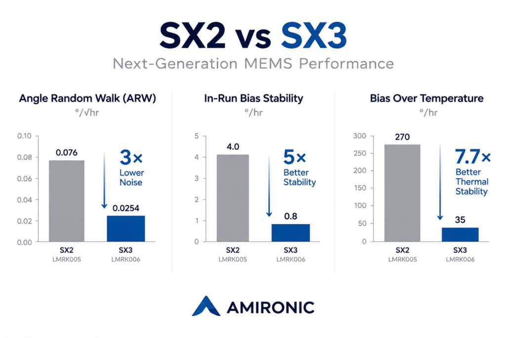
Parameter SX2 – LMRK005 SX3 – LMRK006
Gyro ARW 0.076°/√hr 0.0254°/√hr
In-Run Bias Stability 4°/hr 0.8°/hr
Gyro Bias Over Temperature 270°/hr 35°/hr
Gyro Range ±490°/s ±300°/s
Accelerometer Range ±15g ±15g
Accel Bias Stability 0.020mg 0.020mg
Maximum Output Rate 10kHz 10kHz
Maximum Bandwidth 600Hz 600Hz

The data demonstrates significant improvements in gyroscope performance:

Approximately 67% reduction in random noise: ARW decreases from 0.076 to 0.0254 degrees per square root hour, representing nearly a threefold improvement.

Fivefold improvement in bias stability: In-Run Bias Stability improves from 4°/hr to 0.8°/hr.

Approximately 87% reduction in bias variation over temperature: From 270°/hr to 35°/hr.

From an engineering perspective, these improvements can reduce the contribution of sensor errors to overall system performance, particularly in applications requiring accurate motion estimation over extended periods.

However, the improvements are not uniform across all parameters. Accelerometer bias stability remains at 0.020mg, while the nominal angular rate measurement range of the LandMark 006 is lower than that of the LandMark 005.

Therefore, sensor selection should not be based solely on technology generation, but also on motion dynamics, environmental conditions, bandwidth requirements, and the overall control system architecture.

LandMark 006 specifications are preliminary and may change upon completion of the qualification process.
3. G300D vs. G400D – The Next Generation of Gyroscopes

One of the most significant developments in the transition from SX2 to SX3 is the introduction of the G400D three-axis gyroscope, representing a technological advancement over the G300D.

Both models are based on Silicon MEMS technology and are designed to measure angular rate along three axes, combining compact dimensions, relatively low power consumption, and high-speed signal processing.

The G300D is an established product used in advanced military and civilian systems, including electro-optical stabilization and guidance applications.

The G400D, currently undergoing qualification, has been developed to improve noise performance and bias stability while maintaining interface and processing capabilities suitable for high-speed control systems.

According to the manufacturer’s specifications, the G400D-300-100C version offers the following performance characteristics:

Parameter G300D – SX2 G400D – SX3
Gyro ARW 0.072°/√hr 0.0254°/√hr
In-Run Bias Stability 3.5°/hr 0.8°/hr
Gyro Range ±490°/s ±300°/s
Maximum Output Rate 10kHz 10kHz
Maximum Bandwidth 600Hz 600Hz
Minimum Message Delay 20µs 20µs

The comparison demonstrates approximately 65% lower random noise and more than a fourfold improvement in bias stability.

These improvements are particularly significant in systems where the gyroscope serves as a primary source of angular motion information, such as camera stabilization systems, precision tracking systems, and unmanned platforms.

When a control system receives lower-noise measurements, it may be possible to reduce aggressive filtering, improving the balance between measurement accuracy and response speed.

However, overall system performance also depends on stabilization motors, control algorithms, mechanical design, and vibration conditions.

VELOX Plus – Fast Response Without Compromising Measurement Accuracy

Gladiator Technologies’ VELOX Plus technology enables high-speed inertial data transmission with low digital latency.

Its capabilities include:

  • Data output rates of up to 10kHz.
  • Bandwidth of up to 600Hz.
  • External synchronization at rates of up to 10kHz.
  • Digital message delay as low as 20 microseconds in supported configurations.
  • Configurable communication parameters to meet system requirements.

The combination of low-noise sensing and high-speed processing is particularly important in stabilization systems requiring high control bandwidth.

In such systems, digital noise filtering can introduce additional latency and affect the stability margins of the control loop.

Therefore, improving measurement quality at the sensor level may provide a significant advantage over solutions that rely primarily on additional digital filtering.

4. LandMark 005 vs. LandMark 006 – Advancing IMU Performance

While the G300D and G400D gyroscopes measure angular rate along three axes, the LandMark 005 and LandMark 006 IMUs also integrate three accelerometer axes.

The result is a six-axis Inertial Measurement Unit (IMU) capable of providing angular motion and linear acceleration data.

The SX2-based LandMark 005 is used in applications including flight control, precision stabilization, electro-optical sensing systems, and short-term inertial navigation.

The SX3-based LandMark 006, currently undergoing qualification, is designed to deliver improved gyroscope performance within the same category of compact IMUs.

One of its key advantages is improved gyroscope bias stability, which may reduce accumulated errors when a system must estimate motion without continuous external corrections.

What About Accelerometer Performance?

It is important to distinguish between improvements in gyroscope performance and improvements in accelerometer performance.

In the transition from LandMark 005 to LandMark 006, the primary advancement is in gyroscope performance. Accelerometer specifications remain similar, with a ±15g measurement range, noise density of 40µg/√Hz, and bias stability of 0.020mg, according to the manufacturer’s latest generation data.

This means that SX3 does not necessarily provide equal improvements across all IMU components. Instead, it focuses on enhancing the parameters most critical to precision stabilization and accurate angular motion measurements.

5. LandMark 008 – The Next Step in IMU Evolution

While LandMark 006 focuses primarily on improving gyroscope performance, the LandMark 008 IMU, currently under development, is designed to introduce advancements in both gyroscope and accelerometer performance.

This represents an important technological direction for systems operating in highly dynamic environments, where both low noise and extended measurement ranges are required.

According to preliminary information from Gladiator Technologies, the LandMark 008 development targets include:

  • Angular rate measurement ranges of ±300, ±490, ±1,000, and ±2,000 degrees per second.
  • Open-Loop MEMS accelerometers with measurement ranges of ±40g and ±70g.
  • Target accelerometer noise density of 2.5 to 4µg/√Hz.
  • Gyroscope bias stability of 0.8°/hr.
  • Improved short-term and long-term accelerometer bias stability.
  • Compact dimensions and a target weight of up to 50 grams.

The transition to lower-noise accelerometers with wider measurement ranges may be particularly significant in systems experiencing rapid changes in linear acceleration.

For example, in unmanned aerial vehicles, guidance systems, and mobile platforms, accelerometers must handle combinations of maneuvering acceleration, mechanical vibration, and changes in direction.

In such systems, improving gyroscope performance alone may not be sufficient. Accelerometer measurement quality also influences navigation and motion estimation performance.

LandMark 008 therefore represents a broader technological advancement, aimed at improving overall inertial measurement performance rather than focusing solely on the gyroscope.

It is important to note that LandMark 008 is currently under development. The specifications presented are preliminary performance targets and may change before development and product qualification are completed.

6. Operational Case Study – How Does IMU Quality Affect EO/IR Stabilization Performance?

To understand the practical significance of the transition from SX2 to SX3, let us examine an engineering scenario simulating an electro-optical/infrared (EO/IR) surveillance system mounted on an unmanned aerial vehicle (UAV).

Such a system must maintain a stable line of sight toward a target, even when the platform is exposed to engine vibrations, wind gusts, changes in direction, and rapid maneuvers.

The system uses a gyroscope or an Inertial Measurement Unit (IMU) to measure the platform’s angular motion. The measurement data is transmitted to the stabilization controller, which calculates the required corrections and drives the system’s stabilization motors.

The more accurate and stable the inertial measurements, the lower the contribution of sensor errors to line-of-sight disturbances.

Comparison Scenario – Three Levels of Inertial Sensor Performance

We will examine three possible alternatives:

Option A – Basic MEMS Sensor

An entry-level inertial sensor representing a solution with relatively high noise and limited bias stability.

Option B – SX2 LandMark 005

An advanced six-axis IMU combining low-noise gyroscopes with VELOX technology for high-speed data processing.

Option C – SX3 LandMark 006

A next-generation IMU offering significant improvements in gyroscope noise and bias stability while maintaining high-speed processing capabilities.

For this comparison, we assume that all three sensors are installed in the same system under identical environmental conditions, with no changes to the motors, mechanical structure, or control system.

6.1 Sensor Performance Comparison

Parameter Basic MEMS SX2 – LMRK005 SX3 – LMRK006
Gyro ARW 0.30°/√hr 0.076°/√hr 0.0254°/√hr
In-Run Bias Stability 20°/hr 4°/hr 0.8°/hr
Gyro Bias Over Temperature 500°/hr 270°/hr 35°/hr

The basic MEMS sensor is a hypothetical model used for engineering illustration and does not represent any specific commercial product. SX2 specifications are based on the LandMark 005, while SX3 specifications are based on the preliminary C-grade LandMark 006 datasheet.

The performance differences are substantial.

Compared with the basic MEMS sensor, LandMark 005 offers nearly four times lower gyroscope noise, while LandMark 006 delivers almost twelve times lower noise.

Bias stability also improves significantly, from 20°/hr for the basic sensor to 4°/hr for SX2 and 0.8°/hr for SX3.

But how do these numbers translate into actual measurement performance?

6.2 The Impact of Gyroscope Noise on Angular Error

Assume that the stabilization system must estimate angular displacement over a period of 60 seconds without external angular corrections.

Gyroscope noise introduces random angular error, whose typical magnitude increases with the square root of measurement time.

Assuming white noise and considering only the ARW contribution, we can estimate the standard deviation of angular error after one minute.

Sensor Type Typical Angular Error After 60 Seconds
Basic MEMS 0.0387°
SX2 – LandMark 005 0.0098°
SX3 – LandMark 006 0.0033°

The results demonstrate a significant advantage for the SX3 generation.

Compared with the basic MEMS sensor, the angular error component caused by random noise is reduced by nearly a factor of twelve.

Compared with SX2, the error is reduced by almost a factor of three.

In electro-optical systems with high optical magnification, such improvements can be particularly significant, as even small angular movements may result in noticeable image displacement.

It is important to emphasize that this is a theoretical calculation of the sensor’s random noise contribution only, not a measurement of the overall stabilization error of an EO/IR system.

6.3 The Impact of Bias Stability on Accumulated Error

Unlike random noise, gyroscope bias can introduce a systematic error in angular estimation.

For example, if a gyroscope exhibits a constant bias of one degree per hour, integrating its measurements over one hour will result in an angular error of one degree, assuming no external corrections.

In stabilization and navigation systems, unexpected changes in bias can affect motion estimation accuracy and may require corrections using additional sensors.

In-Run Bias Stability values provide an indication of sensor stability but do not necessarily represent a constant bias that can be directly multiplied by operating time.

Therefore, these values alone cannot be used to calculate accumulated angular error over a specific period. Such calculations require an error model that accounts for bias behavior, measurement noise, environmental conditions, and the system’s correction methods.

Nevertheless, the difference between 20°/hr for the basic MEMS sensor, 4°/hr for SX2, and 0.8°/hr for SX3 illustrates the improvement in measurement stability.

6.4 Operational Implications – EO/IR Stabilization Systems

In an electro-optical surveillance system, improved sensor performance may provide several important advantages.

Improved Stabilization Accuracy

Lower measurement noise reduces the sensor’s contribution to line-of-sight disturbances and errors, potentially helping maintain a more stable image.

Enhanced Tracking Performance

When the control system receives more accurate angular motion information, it may improve the quality of motion estimation used for target tracking, depending on the tracking system’s characteristics.

Reduced Need for Aggressive Filtering

A lower-noise sensor may allow less aggressive filtering, reducing the additional latency introduced into the control system.

Greater Stability Under Temperature Variations

Improved bias stability across the operating temperature range may reduce measurement errors as the system transitions between different environmental conditions.

Support for GPS-Denied Navigation

In systems relying on inertial measurements for motion estimation without continuous external corrections, lower noise and improved bias stability may reduce the rate of error accumulation.

6.5 Does SX3 Guarantee Better Operational Performance?

The transition from SX2 to SX3 offers significant improvements in key inertial measurement parameters.

However, the operational performance of a complete system is not determined by the sensor alone.

Stabilization accuracy also depends on platform structure, vibration frequencies, stabilization motors, control system bandwidth, algorithms, and system behavior under changing environmental conditions.

Therefore, a threefold reduction in gyroscope noise does not necessarily translate into a threefold improvement in overall stabilization accuracy.

The primary advantage of SX3 is its reduced contribution to measurement errors, enabling system engineers to develop more accurate solutions and address increasingly demanding performance requirements.

7. Conclusion – SX3 as the Foundation for Next-Generation Inertial Systems

The transition from SX2 to SX3 by Gladiator Technologies reflects a major trend in MEMS technology: improving measurement quality while maintaining compact dimensions, high bandwidth, and low latency.

The G300D gyroscope and LandMark 005 IMU continue to provide established solutions for applications requiring precise inertial measurements.

The G400D gyroscope and LandMark 006 IMU, currently undergoing qualification, demonstrate significant improvements in gyroscope noise and bias stability.

Looking ahead, the LandMark 008 IMU, currently under development, is expected to expand next-generation capabilities by integrating advanced accelerometers with lower noise and wider measurement ranges.

For engineers designing stabilization, navigation, control, and tracking systems, these developments offer opportunities to select inertial solutions tailored to increasingly demanding performance requirements.

Amironic Ltd., the official representative of Gladiator Technologies in Israel, provides technical and commercial support for selecting gyroscopes, accelerometers, and IMUs for advanced military, industrial, and civilian applications.

For additional information, technical specifications, or assistance in selecting the appropriate inertial solution, please contact the Amironic team.

www.amironic.co.il

8. Tactical-Grade MEMS – Key Concepts in Inertial Sensor Technology

The term Tactical-Grade refers to a performance category of inertial sensors designed for applications requiring higher accuracy, stability, and reliability than basic commercial MEMS solutions.

Tactical-Grade MEMS sensors are used in a wide range of systems, including unmanned aerial vehicles (UAVs), electro-optical/infrared (EO/IR) stabilization systems, Inertial Navigation Systems (INS), guidance systems, and advanced military platforms.

Unlike Consumer-Grade or Industrial-Grade sensors, which are generally intended for applications with less demanding accuracy requirements, Tactical-Grade sensors are designed to provide a combination of low noise, improved bias stability, thermal calibration, and reliable performance under challenging environmental conditions.

It is important to note that Tactical-Grade is not a universally standardized or mandatory performance classification. Sensor classification depends on parameters such as Bias Instability, Angle Random Walk, thermal stability, vibration sensitivity, and specific application requirements.

Tactical-Grade Gyroscope

A tactical-grade gyroscope designed to measure angular rate with high accuracy and improved stability. These sensors are suitable for stabilization systems, motion control, navigation, and attitude estimation applications.

Tactical-Grade IMU

An Inertial Measurement Unit typically integrating three gyroscope axes and three accelerometer axes. Tactical-Grade IMUs are used in systems requiring accurate motion estimation, including military applications and autonomous platforms.

Low-Noise MEMS Gyroscope

A MEMS gyroscope with low measurement noise, helping reduce the contribution of random noise to accumulated angular error. This characteristic is particularly important in precision stabilization systems and inertial navigation applications.

High-Bandwidth IMU

An IMU capable of measuring and transmitting motion data at high frequencies. High bandwidth is important in fast control systems, but it must be evaluated alongside measurement noise and digital latency.

Low-Latency Inertial Sensors

Inertial sensors designed to minimize measurement and processing delays. Low latency can improve the responsiveness of stabilization and control systems, particularly when rapid correction of angular motion is required.

GPS-Denied Navigation

Navigation in environments where GPS or GNSS signals are unavailable, disrupted, or unreliable. In such systems, inertial sensor quality influences the rate at which navigation errors accumulate between external position updates.

Assured Positioning, Navigation and Timing – APNT

A system-level approach designed to ensure the availability and reliability of positioning, navigation, and timing information, even under challenging conditions. Advanced inertial sensors can play an important role in APNT architectures when integrated with additional information sources.

SWaP-C – Size, Weight, Power and Cost

Four key parameters in electronic system design: size, weight, power consumption, and cost.

In military systems, unmanned aerial vehicles, and portable platforms, engineers often face complex trade-offs between sensor performance and SWaP-C constraints.

9. Frequently Asked Questions – Tactical MEMS, SX2 and SX3

What Is the Difference Between a Tactical-Grade IMU and an Industrial-Grade IMU?

The primary difference lies in the sensor performance requirements, particularly measurement noise, bias stability, thermal behavior, and the ability to operate under challenging environmental conditions.

Tactical-Grade IMUs are generally designed for applications where even small measurement errors can affect overall system performance, such as inertial navigation, precision stabilization, and military systems.

However, there is no universally standardized boundary between these categories, and actual manufacturer specifications should always be compared.

What Is the Difference Between Tactical-Grade and Navigation-Grade MEMS?

Navigation-Grade generally refers to a higher level of inertial sensor performance, with particularly demanding requirements for bias stability, measurement noise, and accumulated errors.

Tactical-Grade sensors are suitable for a broad range of stabilization, control, and navigation applications, while Navigation-Grade sensors are intended for applications requiring higher navigation accuracy over extended periods without frequent external corrections.

The exact classification depends on the application requirements and the sensor’s demonstrated performance.

Is SX3 More Accurate Than SX2?

For the models examined, the SX3 generation offers significant improvements in gyroscope performance.

For example, the C-grade LandMark 006 has a preliminary ARW specification of 0.0254°/√hr, compared with 0.076°/√hr for the LandMark 005, according to the datasheets reviewed.

In addition, In-Run Bias Stability improves from 4°/hr to 0.8°/hr.

However, overall accuracy also depends on the measurement range, environmental conditions, and characteristics of the control or navigation system.

What Are the Advantages of a Tactical MEMS Gyroscope in EO/IR Systems?

In electro-optical systems, gyroscopes measure angular motion and support line-of-sight stabilization.

A gyroscope with low noise, high bias stability, and low latency can reduce the contribution of sensor errors and improve the quality of information supplied to the stabilization controller.

These advantages are particularly important in high-magnification surveillance systems and platforms exposed to vibration.

Can a Tactical-Grade IMU Operate Without GPS?

Yes. An IMU independently measures angular motion and acceleration and does not require GPS signals to perform these measurements.

However, an IMU alone does not provide absolute position, and using its measurements for inertial navigation leads to accumulated errors over time.

Therefore, advanced navigation systems often combine an IMU with a navigation computer and additional correction sources.

Which Is More Important in a Stabilization System – ARW or Bias Stability?

Both parameters are important, but they describe different error mechanisms.

ARW describes the effect of random noise on accumulated angular error, while Bias Stability describes the stability of the measurement bias during operation.

In high-speed stabilization systems, bandwidth, measurement noise within the relevant frequency range, and digital latency can also be extremely important.

Can a MEMS Gyroscope Replace a FOG Gyroscope?

In certain applications, yes.

MEMS-based gyroscopes can offer advantages in size, weight, power consumption, and cost compared with some Fiber Optic Gyroscope (FOG) solutions.

However, certain FOG sensors still provide superior performance in parameters such as bias stability and long-term noise.

The choice of technology depends on accuracy requirements, operating duration, environmental conditions, and system constraints.

What Are the Advantages of SX3 in UAV and UAS Applications?

In unmanned aerial vehicles, inertial sensors are used for flight control, attitude estimation, navigation, and electro-optical payload stabilization.

The SX3 generation may offer advantages in applications where lower gyroscope noise and improved bias stability contribute to more accurate motion estimation.

The impact on overall aircraft performance depends on the control system, sensor fusion algorithms, and operating conditions.

What Is the Difference Between G300D and G400D?

Both products are three-axis digital gyroscopes developed by Gladiator Technologies.

The G300D is based on the SX2 generation, while the G400D belongs to the SX3 generation and is designed to provide improved noise performance and bias stability.

The G400D is currently undergoing qualification, and its preliminary specifications indicate the potential for significant improvements in stabilization and precision measurement applications.

What Is the Difference Between LandMark 005, LandMark 006 and LandMark 008?

LandMark 005 is an established IMU based on SX2 technology.

LandMark 006 belongs to the SX3 generation, is currently undergoing qualification, and focuses on improved gyroscope performance.

LandMark 008 is under development and is designed to combine advanced gyroscopes with lower-noise accelerometers offering wider measurement ranges.

Are Gladiator Technologies Sensors Subject to ITAR Regulations?

According to the manufacturer’s documentation, the Gladiator Technologies products presented are identified as Non-ITAR.

However, specific export classifications, licensing requirements, and restrictions on use or transfer depend on the part number, product version, destination, and applicable regulations.

The current export classification should always be verified before any international transaction or transfer.

Where Can I Purchase Tactical-Grade IMUs and MEMS Gyroscopes in Israel?

Amironic Ltd. is the official representative of Gladiator Technologies in Israel, providing gyroscopes, accelerometers, and IMU solutions for military, industrial, and civilian applications.

The company assists customers in selecting inertial solutions based on noise requirements, bias stability, bandwidth, measurement ranges, dimensions, and environmental conditions.

For additional information and assistance in selecting the appropriate Tactical-Grade MEMS solution, please contact Amironic through our website:

www.amironic.co.il

Tags: Gladiator_Technologies

Related Articles

SX3: Pushing MEMS Beyond Traditional Stabilization

24/06/2026amironicLTD

How Does a MEMS Sensor Become a Tactical-Grade IMU?

06/08/2026amironicLTD

Why Position Feedback Matters More Than Ever in Counter-UAS Swarm Defense

02/08/2026amironicLTD

Recent Posts

  • SX2 vs. SX3 – The Future of Inertial Sensor Technology
  • Allan Deviation in MEMS Sensors: Understanding Noise and Drift in Gyroscopes and Accelerometers
  • SFR6-32X3/8-2615 Sealing Screw by APM Hexseal – Preventing Liquid Ingress in Electronic Enclosures
  • T1121AB Digital Hour Meter by ENM – Operating Hour Monitoring and Preventive Maintenance for Industrial Equipment
  • IMU Sensors for High-Speed Control Systems – Balancing Noise, Bandwidth, and Latency

Categories

  • Air Switch
  • Circuit Breakers
  • Elapsed Time Indicator
  • Feedthrough
  • Footswitches
  • Gears & Transmission
  • Hour Meters
  • Infra Red Switches
  • INFRARED LAMPS
  • Low Noise Inertial MEMS
  • Mechanics
  • MEMS Gyroscope
  • MEMS Inertial
  • Microelectronics
  • Motors
  • Position Sensors
  • Power Supply
  • Pressure Sensors
  • Pressure Switch
  • Sealing
  • Switches
  • Temperature Sensors
  • Tungsten and Molybdenum
  • Uncategorized
  • Vacuum Switches

Quick Contact

Fill out the form and our representatives will return to you

    Name (required)

    Email (required)

    Phone

    Message

    This site is protected by reCAPTCHA and the Google
    Privacy Policy and
    Terms of Service apply.

    Amironic Ltd.

    3 Rabinovich Street, Petah Tikva 4928144 , Israel. Tel: +972-3-9047744 E-mail: office@amironic.co.il
    Email
    Facebook
    Twitter
    LinkedIn
    YouTube
    Press on the ISO Certificate below for download
    ISO 9001:2015 Certification
    • MEMS Inertial
    • Circuit Breakers
    • Footswitches
    • Mechanical & Transmissions
    • Sensors
    • Motors
    • Electronics
    • Hand Control
    • Power Solutions

    News

    • SX2 vs. SX3 – The Future of Inertial Sensor Technology
    • Allan Deviation in MEMS Sensors: Understanding Noise and Drift in Gyroscopes and Accelerometers
    • SFR6-32X3/8-2615 Sealing Screw by APM Hexseal – Preventing Liquid Ingress in Electronic Enclosures
    • T1121AB Digital Hour Meter by ENM – Operating Hour Monitoring and Preventive Maintenance for Industrial Equipment
    • IMU Sensors for High-Speed Control Systems – Balancing Noise, Bandwidth, and Latency
    About AmironicContactעברית
    © 2022 Amironic All rights reserved. All Trademarks are the property of their respective owners.
    • Increase Font
    • Decrease Font
    • Black & White
    • Inverse Colors
    • Highlight Links
    • Regular Font
    • Reset