


Tactical-Grade is not a datasheet specification. It is the result of rigorous engineering.
MEMS
   ↓
Calibration
   ↓
Characterization
   ↓
Temperature
   ↓
Vibration
   ↓
Shock
   ↓
Verification
   ↓
Tactical Grade IMU
Every MEMS Sensor Starts the Same. Not Every IMU Ends Up Tactical-Grade.
MEMS sensors are now found in almost every system that measures motion, acceleration, or angular rate. They are used in unmanned aerial systems (UAS), autonomous vehicles, stabilized platforms, inertial navigation systems, industrial automation, robotics, and countless other motion-control applications.
Their advantages are obvious: they are compact, lightweight, power-efficient, and can be manufactured in high volumes at a relatively low cost.
But a MEMS sensor alone is not a Tactical-Grade Inertial Measurement Unit (IMU).
Even a high-performance MEMS gyroscope or precision MEMS accelerometer cannot guarantee that an IMU will continue to deliver accurate and repeatable measurements when temperatures change, engines introduce vibration, the platform experiences mechanical shock, or the system operates for extended periods in harsh real-world environments.
Transforming a MEMS sensor into a Tactical-Grade MEMS IMU requires a comprehensive engineering process that extends far beyond sensor selection. It typically includes:
- Selecting high-performance MEMS gyroscopes and accelerometers
- Mechanical and electronic system design
- Individual sensor calibration
- Temperature characterization across the full operating range
- Vibration and shock qualification
- Performance verification after environmental exposure
- Repeatability validation across multiple measurements and production units
Gladiator Technologies recently provided a rare look inside a process that most users never get to see. Their published images reveal environmental test chambers, temperature cycling, vibration testing, shock testing, and post-test performance verification – illustrating that environmental qualification is far more than a simple survivability test.
The real objective is to verify that the IMU continues to produce stable, accurate, and repeatable measurements before, during, and after exposure to demanding environmental conditions.
So the real question is not simply:
Does the IMU still operate?
The more important question is:
Can you still trust its measurements after the environment has changed?
That is where the true difference between a standard MEMS sensor and a Tactical-Grade IMU begins.
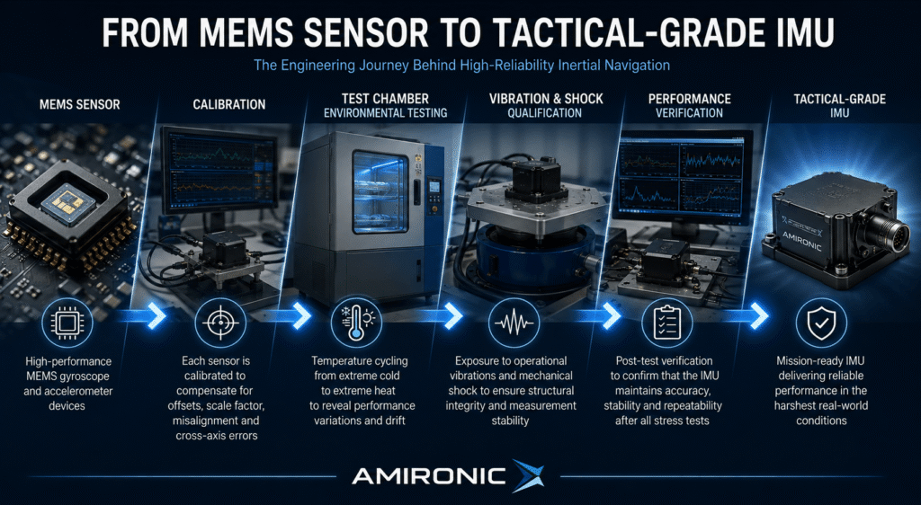
What transforms a tiny MEMS sensor into an Inertial Measurement Unit (IMU) trusted for precision navigation, stabilization, and guidance – even after extreme vibration, temperature cycling, and mechanical shock?
The answer lies in the engineering process behind a Tactical-Grade MEMS IMU
What Is an Environmental Test Chamber?
In Gladiator Technologies’ recent publication, several images show what appears, at first glance, to be little more than a large metal cabinet. To someone unfamiliar with inertial sensor development, it could easily be mistaken for an industrial oven or a storage enclosure.
In reality, it is one of the most important tools in the development and qualification of a Tactical-Grade MEMS IMU.
An Environmental Test Chamber is a precisely controlled test environment that allows engineers to simulate extreme operating conditions in a repeatable and measurable way. Instead of waiting months or even years for an IMU to encounter real-world environmental stresses, engineers can recreate those conditions inside the laboratory and observe exactly how the system responds.
The ability to reproduce identical test conditions over and over again is critical. It allows engineers to measure how environmental changes affect sensor performance, compare results between test cycles, and verify that the IMU continues to operate within its specified performance limits.
However, there is an important distinction that is often overlooked.
The purpose of an Environmental Test Chamber is not simply to determine whether an IMU survives environmental exposure.
Its real purpose is to determine whether the IMU continues to deliver the same level of measurement accuracy, stability, and repeatability after being exposed to extreme environmental conditions.
That difference is fundamental.
An IMU that still powers up after testing is not necessarily an IMU that can still be trusted.
A Tactical-Grade MEMS IMU must continue to deliver consistent bias stability, repeatable measurements, and predictable performance long after repeated environmental stress testing.
In other words, the Environmental Test Chamber is not designed to prove survivability – it is designed to reveal how sensor performance changes as the operating environment changes.
And that is only the beginning.
Inside these environmental chambers, engineers perform a series of qualification tests, each designed to evaluate a different aspect of IMU performance. One of the most critical is Temperature Cycling, where the sensor is repeatedly exposed to extreme hot and cold conditions to characterize its behavior across the entire operating temperature range.
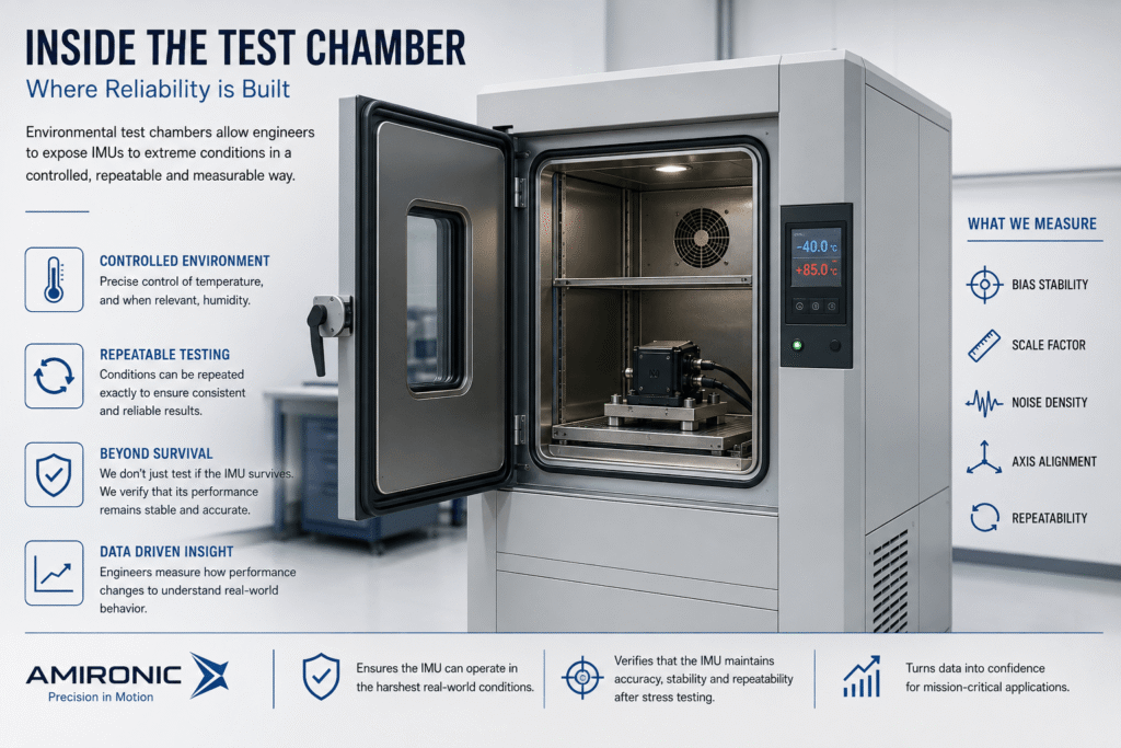
An Environmental Test Chamber enables engineers to recreate extreme operating environments under controlled, repeatable laboratory conditions. The objective is not merely to confirm that the IMU survives environmental testing, but to verify that it continues to deliver accurate, stable, and repeatable measurements after exposure to extreme temperatures and harsh environmental stresses.
Temperature Cycling – More Than a Temperature Test
Ask an inertial systems engineer which qualification test is most critical in the development of a Tactical-Grade MEMS IMU, and many will give the same answer:
Temperature Cycling.
The reason is straightforward.
Most navigation, stabilization, and guidance systems never operate at room temperature.
A UAV may begin its mission with an internal temperature of approximately 25°C, but within minutes the electronics generate heat, the propulsion system raises the internal temperature, solar radiation warms the enclosure, and changes in altitude expose the system to an entirely different thermal environment.
The same applies to missile guidance systems, EO/IR payloads, ground vehicles, and other mission-critical platforms, where temperature can change by tens of degrees during a single mission.
This is precisely why Temperature Cycling is such an essential part of IMU qualification.
During the test, the IMU is repeatedly cycled between low and high temperatures inside an Environmental Test Chamber. The objective is not simply to demonstrate that the hardware continues to operate, but to characterize how temperature affects the sensor’s performance throughout its entire operating range.
Engineers typically monitor parameters such as:
- Bias Drift
- Scale Factor Drift
- Noise
- Axis Alignment
- Repeatability
Although changes in these parameters may appear small, they can accumulate over time and significantly affect inertial navigation performance, particularly in GPS-denied environments or other applications requiring high-precision dead reckoning over extended mission durations.
For this reason, IMU qualification goes far beyond testing at room temperature. Engineers evaluate performance across the complete specified operating temperature range and verify that these critical parameters remain stable after dozens – and often hundreds – of thermal cycles.
In other words, Temperature Cycling is not a survivability test. It is a stability test.
Its purpose is not merely to confirm that the IMU continues to function, but to verify that every measurement remains accurate, stable, and repeatable regardless of the surrounding thermal environment.
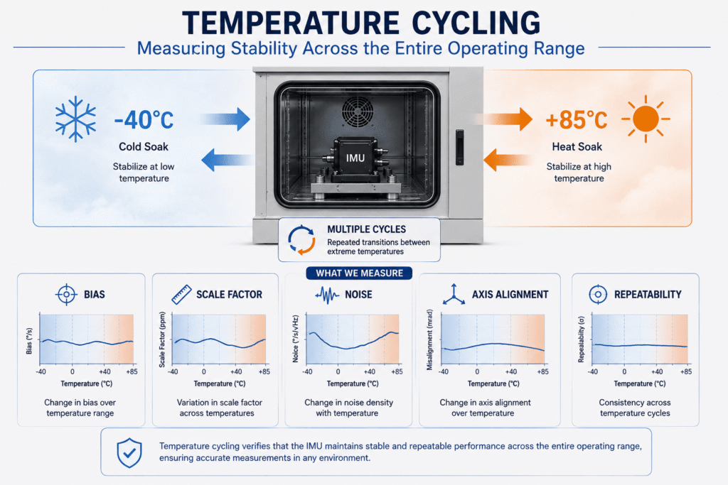
Temperature Cycling evaluates how a Tactical-Grade MEMS IMU performs across its full operating temperature range. Rather than simply confirming survivability, engineers measure critical performance parameters – including Bias Drift, Scale Factor Drift, Noise, Axis Alignment, and Repeatability – to verify that the IMU maintains accurate, stable, and repeatable measurements throughout repeated thermal cycling.
Vibration Testing – When Vibration Becomes a Navigation Error
Every moving platform generates vibration.
It may originate from the electric motor of a small UAV, the diesel engine of a military ground vehicle, the rotor system of a helicopter, or the propulsion system of a guided missile. Regardless of the platform, vibration is an unavoidable part of the operating environment.
For an Inertial Measurement Unit (IMU), vibration is more than a mechanical load that could lead to wear or structural damage. It can directly affect measurement accuracy and long-term navigation performance.
This is why Vibration Testing is an essential part of qualifying a Tactical-Grade MEMS IMU.
Not Every Vibration Is Visible in the Measurements
One common misconception is that if the platform maintains a constant attitude, the IMU should report a perfectly stable output.
In reality, high-frequency vibration can interact with the microscopic mechanical structures inside MEMS gyroscopes and accelerometers, causing measurement errors that do not correspond to any real platform motion.
One of the best-known examples is Vibration Rectification Error (VRE) – a phenomenon in which vibration at specific frequencies produces a false sensor output, even though no actual rotation or acceleration has occurred along the measured axis.
As a result, an apparently stable platform may still cause the IMU to report motion that does not exist.
What Is Evaluated During Vibration Testing?
During qualification, the IMU is mounted on a Shaker Table, which reproduces the vibration environment expected in real-world operation.
Depending on the application, engineers expose the system to controlled vibration profiles covering different frequencies, amplitudes, and acceleration levels while continuously monitoring sensor performance.
The objective is not simply to verify that the enclosure remains intact or that fasteners have not loosened.
Instead, engineers evaluate whether the IMU continues to maintain its specified performance while subjected to continuous vibration.
Typical parameters include:
- Bias Stability
- Noise Performance
- Axis Alignment
- Repeatability
- Resistance to Vibration Rectification Error (VRE)
In other words, vibration qualification is not only about mechanical durability – it is about measurement integrity.
Why Is This So Important for Tactical Systems?
In applications such as unmanned systems, EO/IR stabilized payloads, inertial navigation systems (INS), guided munitions, and precision stabilization platforms, even a small measurement error repeated thousands of times per second can accumulate into a significant navigation or pointing error.
That is why a Tactical-Grade MEMS IMU must demonstrate that it maintains its specified performance even under continuous vibration throughout the mission.
Only after successfully completing vibration qualification can the system move to the next stage of environmental testing – Shock Testing.
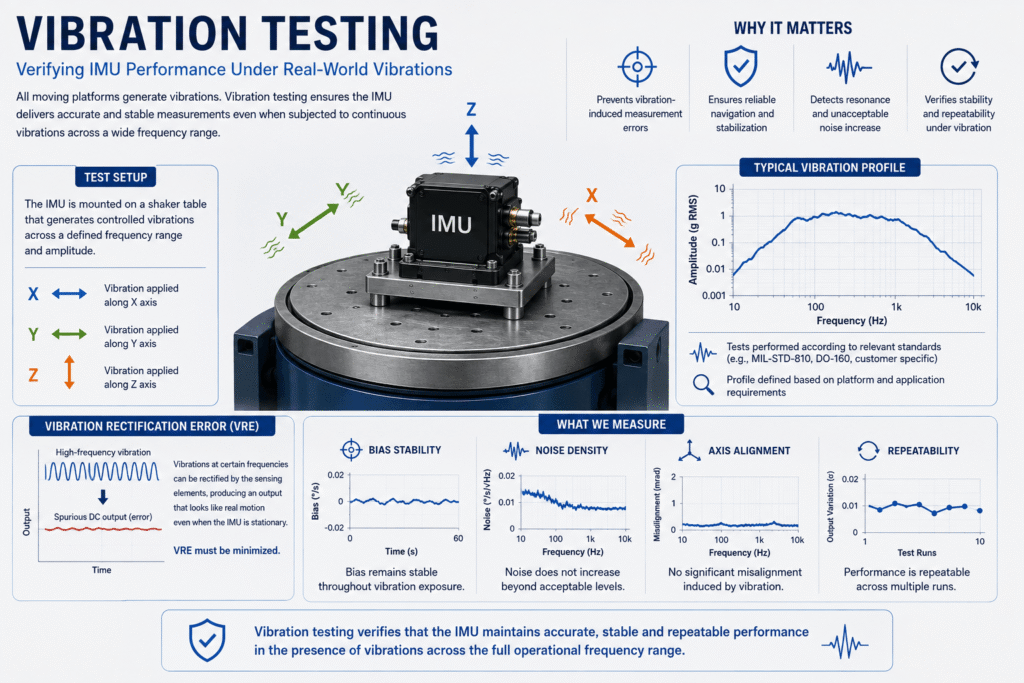
Vibration Testing simulates the real operating environment of a Tactical-Grade MEMS IMU to evaluate the effects of continuous vibration on sensor performance. In addition to verifying mechanical integrity, engineers monitor critical parameters such as Bias Stability, Noise Performance, Axis Alignment, Repeatability, and resistance to Vibration Rectification Error (VRE), ensuring accurate and reliable inertial measurements in demanding aerospace and defense applications.
Shock Testing – Does an IMU Remain Accurate After Impact?
Not every mission-critical event happens gradually.
An IMU may experience a hard UAV landing, the impact transmitted through a military vehicle’s suspension, the intense acceleration of a missile launch, or severe mechanical loads during transportation, handling, or maintenance.
For most electronic devices, the primary question is simple:
Does it still work after the event?
For a Tactical-Grade IMU, that question is only the beginning.
The real question is whether the sensor continues to deliver the same level of measurement accuracy after experiencing a high-g mechanical shock.
Shock Is More Than a Mechanical Load
A Shock Test is designed to simulate short-duration, high-acceleration events that an IMU may encounter during its operational life.
Unlike Vibration Testing, which evaluates continuous cyclic loading, Shock Testing focuses on the system’s response to a single, high-energy event.
These events can introduce microscopic changes within the sensor package, the MEMS structures themselves, or the overall mechanical assembly. Although such changes may be invisible to the naked eye, they can still affect the accuracy of inertial measurements.
For this reason, the test does not end when the impact is over.
The most important evaluation begins immediately afterward.
What Is Evaluated After a Shock Test?
Engineers are not simply looking for cracked housings or visible mechanical damage.
Instead, they determine whether the shock event has altered any of the IMU’s critical performance parameters, including:
- Bias Stability
- Scale Factor
- Axis Alignment
- Noise Performance
- Repeatability
Even small changes in these characteristics can accumulate over time and degrade the performance of an Inertial Navigation System (INS).
That is why every shock event is followed by a complete performance verification process. Measurements are compared with pre-test baseline data to confirm that the IMU still meets its original performance specifications.
When Accuracy Matters More Than Survivability
It is entirely possible to design an enclosure that protects an IMU from mechanical damage.
However, surviving the impact does not guarantee that the sensor still measures with the same precision.
In applications such as guided missiles, EO/IR stabilized systems, Inertial Navigation Systems (INS), and other precision guidance platforms, even a slight shift in sensor performance can grow into a significant navigation or pointing error over the course of a mission.
This is why Shock Testing is not performed simply to prove that the hardware survived.
It is performed to verify that the IMU continues to generate measurement data that engineers can trust.
In other words, for a high-performance navigation system, the most important event is not the impact itself – it is the first measurement that follows it.
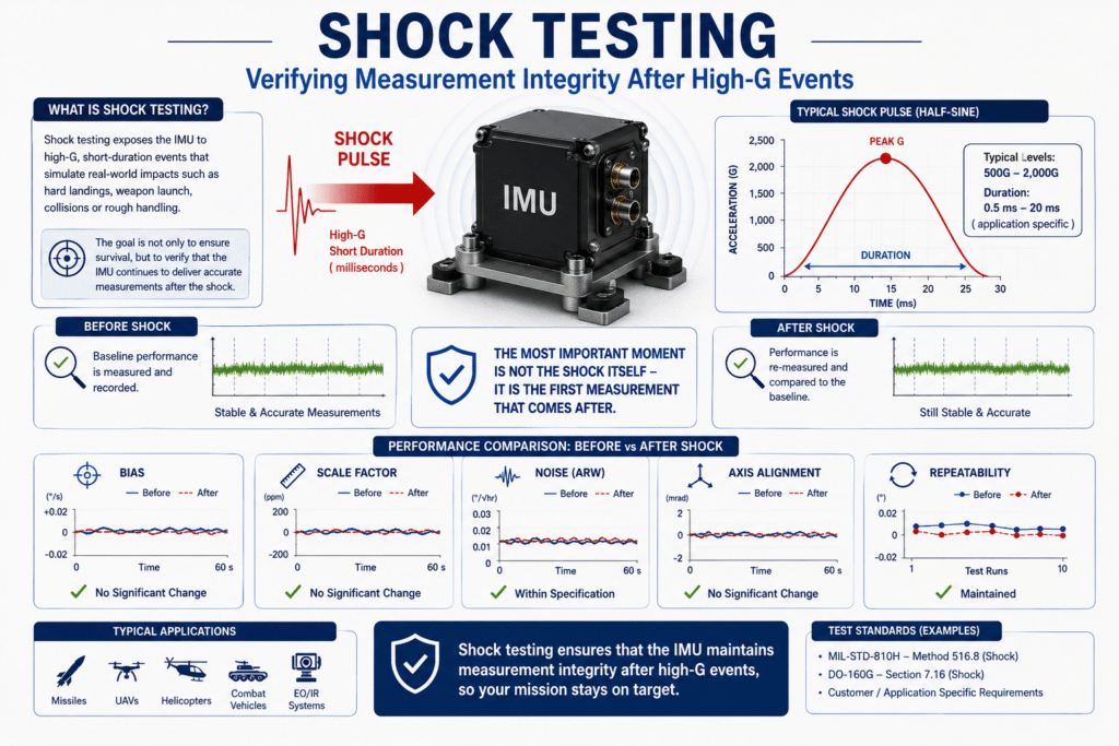
For an Inertial Measurement Unit (IMU), surviving a shock event is only part of the qualification process. In inertial navigation applications, the real requirement is to ensure that every measurement remains accurate, stable, and repeatable after mechanical shock. This is why Shock Testing is always followed by comprehensive performance verification and direct comparison of pre-test and post-test measurement data.
Repeatability – The Performance Metric Many Engineers Overlook
When evaluating an Inertial Measurement Unit (IMU), most engineers naturally focus on specifications such as Bias Stability, Noise, Bandwidth, or Accuracy.
These are all essential performance metrics.
However, there is another characteristic that often receives far less attention, despite being just as important in precision navigation systems.
That characteristic is Repeatability.
What Is Repeatability?
Repeatability describes an IMU’s ability to produce the same measurement repeatedly under identical operating conditions.
Imagine performing exactly the same test ten times.
If the results are nearly identical every time, the IMU demonstrates excellent repeatability.
If the measurements vary from one test to the next despite unchanged conditions, repeatability is poor.
In other words, repeatability does not answer the question:
“How accurate is this measurement?”
Instead, it answers a more fundamental question:
“Can I expect the same measurement every time?”
Why Does It Matter?
An Inertial Navigation System (INS) never relies on a single measurement.
Instead, it processes thousands – and often tens of thousands – of measurements every second to calculate position, velocity, and attitude.
If an IMU exhibits a consistent error, that error can often be characterized and compensated for through calibration or sensor fusion algorithms.
However, when the error changes unpredictably from one measurement to the next, compensation becomes significantly more difficult.
Random variation cannot simply be calibrated out.
That is why high repeatability is one of the defining characteristics of a Tactical-Grade MEMS IMU.
Repeatability Is the Ultimate Validation of the Engineering Process
Every qualification step discussed throughout this article – calibration, temperature characterization, vibration testing, shock testing, and performance verification – ultimately serves the same objective:
Ensuring that the IMU behaves the same way tomorrow as it does today.
The purpose of environmental qualification is not merely to demonstrate survivability.
It is to prove that the sensor continues to generate consistent, stable, and repeatable measurements after exposure to demanding operating conditions.
When an IMU maintains high repeatability throughout its qualification process, engineers gain confidence that it will behave just as predictably in the field.
For many inertial navigation engineers, repeatability is not simply another specification – it is one of the strongest indicators of overall IMU quality.
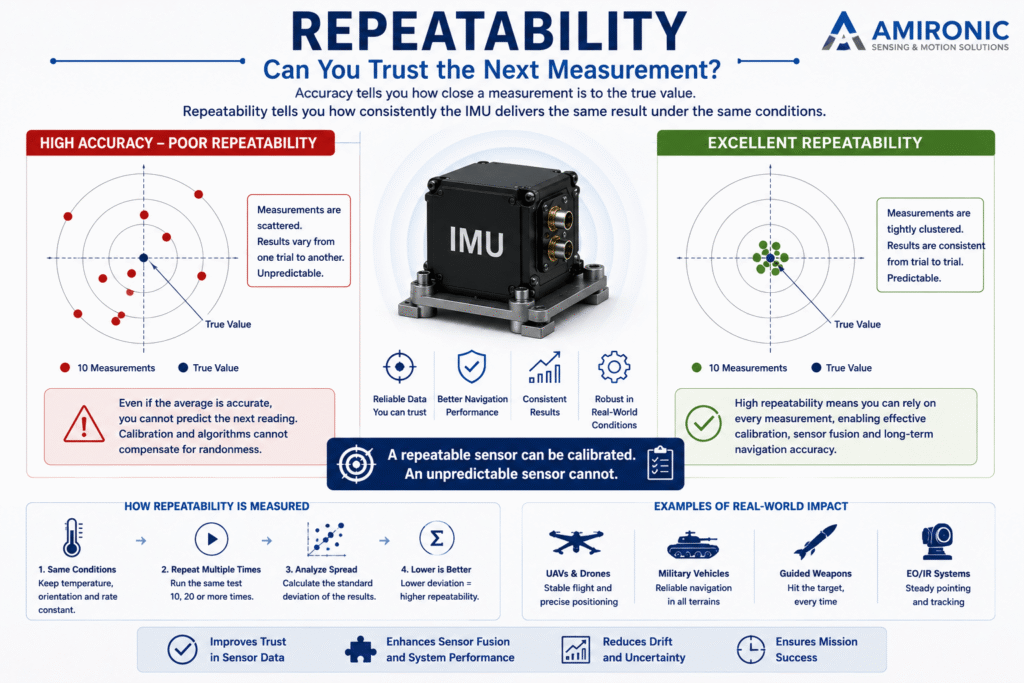
Repeatability is an IMU’s ability to produce the same measurement repeatedly under identical operating conditions. While Accuracy describes how close a measurement is to the true value, Repeatability ensures that measurements remain consistent and predictable over time – a critical requirement for sensor calibration, Sensor Fusion, and high-precision Inertial Navigation Systems (INS).
Quality Verification – The Final Step Before an IMU Leaves the Lab
After an IMU has completed calibration, temperature cycling, vibration qualification, and shock testing, it is tempting to assume that the qualification process is complete.
In reality, the final and perhaps most important step is still ahead.
Before an Inertial Measurement Unit (IMU) can be qualified for deployment, engineers must verify that the entire environmental testing process has not altered its performance.
In other words, surviving the tests is not enough.
The IMU must demonstrate that it still meets the same performance specifications established before environmental qualification began.
Returning to the Baseline
During Quality Verification, engineers repeat the same performance measurements that were performed before environmental testing.
The results are then compared directly with the original baseline to determine whether any critical performance parameters have changed.
Typical parameters include:
- Bias Stability
- Scale Factor
- Noise Density
- Axis Alignment
- Repeatability
This comparison can reveal even the smallest performance shifts – changes that may be invisible during normal operation but could accumulate into significant navigation errors over extended missions.
Verification, Not Assumption
There is no room for assumptions in aerospace and defense applications.
Even if the IMU operated flawlessly throughout every environmental test, engineers must still verify that its performance remains within specification.
That is why qualification does not end when the final vibration or shock test is completed.
It ends only when post-test verification confirms that:
- Measurement accuracy has been maintained.
- Performance remains stable.
- Repeatability is unchanged.
- No significant performance degradation has occurred following environmental exposure.
Only then can the qualification process be considered complete.
More Than Quality Control
It is easy to think of Quality Verification as a final quality-control inspection.
In reality, it is the step that validates the entire engineering process.
If calibration was effective, if temperature cycling introduced no measurable drift, if vibration qualification preserved measurement integrity, and if shock testing caused no degradation, the final verification results will confirm it.
For that reason, Quality Verification can be viewed as the final examination of a Tactical-Grade MEMS IMU.
It is the moment when engineers confirm that everything measured at the beginning of the qualification process remains true after every environmental challenge has been completed.
An Engineering Process – Not a Single Test
Returning to the question that opened this article –
How does a MEMS sensor become a Tactical-Grade IMU?
The answer is now clear.
It is not achieved through a better MEMS sensor alone.
It is not defined by an impressive datasheet.
It is the result of a rigorous engineering and qualification process:
MEMS Sensor Selection → System Design → Calibration → Environmental Test Chamber → Temperature Cycling → Vibration Qualification → Shock Testing → Performance Verification → Tactical-Grade MEMS IMU
Each step adds another layer of confidence.
Each step reduces uncertainty.
Each step increases the likelihood that every measurement can be trusted when the system is deployed in the field.
That is why manufacturers of Tactical-Grade MEMS IMUs invest as much effort in qualification and performance verification as they do in sensor development itself.
Ultimately, the value of an IMU is not defined by its datasheet specifications.
It is defined by its ability to deliver accurate, stable, and repeatable inertial measurements after repeated exposure to the harsh operating environments encountered in real-world aerospace and defense applications.
Tactical-Grade is not a datasheet specification. It is the result of rigorous engineering.
From the Lab to the Battlefield – Why Qualification Matters
The engineering principles described throughout this article are not theoretical. They are applied every day in mission-critical systems where measurement accuracy directly affects navigation, stabilization, and guidance performance.
Although every application presents unique challenges, they all rely on the same foundation: an IMU that continues to deliver accurate, stable, and repeatable measurements even after exposure to demanding environmental conditions.
The following examples illustrate why the qualification process behind a Tactical-Grade MEMS IMU is so important.
Scenario 1 – Turret Stabilization After Repeated Firing
A stabilized turret must maintain weapon pointing accuracy and preserve the line of sight of an EO/IR system, even while the vehicle is moving across rough terrain.
During firing, however, the IMU is exposed to one of the most demanding events it will ever experience: intense mechanical shock, structural vibration, and extremely high acceleration transmitted throughout the turret.
Immediately after every shot, the stabilization system must reacquire and maintain precise pointing.
This is where Shock Testing, Vibration Qualification, and Repeatability Validation become critical.
The objective is not simply to confirm that the IMU continues operating after recoil, but to ensure that Bias Stability, Scale Factor, and Axis Alignment remain unchanged, allowing the first measurement after firing to be just as reliable as the one before it.
When properly qualified, the stabilization system can maintain consistent performance through hundreds of firing cycles.
Scenario 2 – EO/IR Payload on a High-Speed Patrol Vessel
Unlike a single shock event, a fast patrol vessel exposes its sensors to continuous environmental stress.
The IMU experiences constant engine vibration, repeated impacts from waves, and large temperature variations between daytime operation and nighttime deployment.
At the same time, the EO/IR payload must maintain a stable line of sight toward distant targets despite continuous platform motion.
Under these conditions, even a small change in inertial measurements can reduce stabilization accuracy and degrade image quality.
This is why Temperature Cycling, Vibration Qualification, and Performance Verification are essential for IMUs used in maritime stabilization systems.
Their purpose is to ensure stable and repeatable sensor performance throughout long-duration missions in harsh marine environments.
Scenario 3 – Missile Guidance Immediately After Launch
The first moments following launch represent one of the harshest operating conditions an IMU will ever encounter.
Within milliseconds, the system experiences extremely high acceleration, severe mechanical shock, and intense vibration generated by the propulsion system.
Ironically, the IMU’s most important task begins only after these events have occurred.
The guidance system immediately depends on accurate inertial measurements to calculate the missile’s trajectory.
Any change in Bias Stability, Scale Factor, or Axis Alignment introduced during launch can begin accumulating navigation errors from the very first seconds of flight.
For this reason, Shock Testing, Repeatability Validation, and Performance Verification are not performed simply to prove that the IMU survived launch.
They are performed to ensure that the first measurement after launch is every bit as trustworthy as the last measurement made in the laboratory.
The Common Engineering Challenge
Although these examples represent very different defense applications, they all depend on the same engineering principle:
- A stabilized turret must maintain pointing accuracy after every firing cycle.
- An EO/IR payload must remain stable despite continuous vibration and temperature changes.
- A missile guidance system must trust its very first measurement after launch.
In every case, the difference between a standard MEMS sensor and a Tactical-Grade MEMS IMU is not the sensor itself.
It is the rigorous engineering process of calibration, environmental qualification, and performance verification that ensures reliable inertial measurements under the most demanding operating conditions.
Gladiator Technologies‘ qualification philosophy reflects exactly these engineering principles, combining rigorous calibration, environmental qualification, and performance verification to ensure every Tactical-Grade MEMS IMU delivers consistent performance under demanding real-world conditions.
Conclusion
MEMS technology has transformed the world of inertial sensing, making navigation and stabilization systems smaller, lighter, more efficient, and more accessible than ever before.
Yet, as this article has shown, a high-quality MEMS sensor is only the beginning.
Transforming it into a Tactical-Grade Inertial Measurement Unit (IMU) requires a comprehensive engineering process that includes sensor selection, calibration, temperature characterization, vibration qualification, shock testing, repeatability validation, and final performance verification.
Each step serves a single purpose:
To ensure that the IMU continues to deliver accurate, stable, and repeatable measurements long after it leaves the laboratory.
Whether stabilizing a turret, maintaining the line of sight of an EO/IR payload, or guiding a missile during the first moments of flight, the engineering challenge remains the same:
Can every measurement still be trusted after the environment has changed?
Ultimately, the difference between a commercial MEMS IMU and a Tactical-Grade MEMS IMU is not defined by a single specification or by the MEMS sensor alone.
It is defined by the engineering process behind it.
Tactical-Grade is not a datasheet specification. It is the result of rigorous engineering.
🧩 Further Reading and Deeper Insight
This article is part of a broader series exploring the engineering principles behind modern inertial sensing and motion stability in advanced control and navigation systems. For deeper technical context and system-level insights, you may also find the following articles valuable:
- Bridging Control and Navigation: How Advanced MEMS IMUs Are Redefining System Performance
- Gyro and IMU for Advanced Control Systems
- The Silent Problem of Precision Systems – Why Gyros and IMUs Are Control Components, Not Just Sensors
- Why External Sync is Critical in Gyro and IMU Systems
- Stabilization, Tracking & Time Sync: The Foundation of Precise Line-of-Sight Control
- Mission-Grade Stabilization in Dynamic EO/IR Systems: Why Bandwidth, Data Rate, and Phase Lag Define Gimbal Performance
- Why Gladiator? What Truly Differentiates a High-End MEMS IMU Manufacturer
- Common Misconceptions About MEMS Inertial Sensors
- Bias Stability vs. Bias Instability: What really determines the performance of Gyro and IMU systems in stabilization, tracking, and navigation
- Scale Factor in MEMS IMUs – The Error That Quietly Destroys Accuracy
- The IMU Was Excellent. The Image Still Shook.
- 2000Hz IMU? Before You Get Impressed, Understand Three Completely Different Numbers
- SX3: Pushing MEMS Beyond Traditional Stabilization
- Why a Smaller IMU Can Save Months of Development
- Your Image Still Shakes Despite Choosing a Gyroscope with Excellent Bias Stability
- Why Replacing an IMU Can Lead to Weeks of Recalibration
- From IMU to INS: How a Tactical Navigation System Is Really Built
- When GPS Is Lost, It’s Already Too Late to Choose an IMU
- Why Do Counter-UAS Systems Lose Track of a Drone Right After Detecting It?
- When GPS Lies: Why IMUs Are Becoming Mission-Critical in the Era of Autonomous Wingmen
Frequently Asked Questions (FAQ)
Are all IMUs based on MEMS sensors?
No. Inertial Measurement Units can also be built using technologies such as Fiber Optic Gyroscopes (FOG) and Ring Laser Gyroscopes (RLG). However, because of their compact size, low weight, low power consumption, and cost-effectiveness, MEMS sensors have become the dominant technology for modern navigation, stabilization, and motion-control systems.
What is the difference between a MEMS sensor and an IMU?
A MEMS sensor is an individual sensing element, such as a gyroscope or an accelerometer.
An Inertial Measurement Unit (IMU) is a complete system that typically combines multiple MEMS gyroscopes, accelerometers, processing electronics, calibration algorithms, signal conditioning, and communication interfaces to measure motion in three dimensions.
What is an Environmental Test Chamber?
An Environmental Test Chamber is a controlled laboratory system used to simulate extreme operating conditions, including high and low temperatures, thermal cycling, and in some cases humidity.
It allows engineers to evaluate how environmental conditions affect IMU performance before deployment.
Why is Temperature Cycling more important than testing at a single temperature?
Testing at a single temperature only verifies performance under one condition.
Temperature Cycling repeatedly exposes the IMU to hot and cold environments to evaluate long-term stability, thermal drift, and repeatability throughout its specified operating temperature range.
What is the difference between Vibration Testing and Shock Testing?
Vibration Testing evaluates IMU performance under continuous cyclic vibration, while Shock Testing simulates short-duration, high-acceleration events such as missile launch, hard landings, recoil, or mechanical impact.
What is Vibration Rectification Error (VRE)?
Vibration Rectification Error (VRE) is a measurement error that can occur in MEMS sensors when vibration at specific frequencies generates a false output, even though no real acceleration or rotation has occurred.
Why is Repeatability so important?
Repeatability is the ability of an IMU to produce consistent measurements under identical operating conditions.
High repeatability is essential for calibration, Sensor Fusion, dead reckoning, and high-precision inertial navigation because predictable measurements are easier to compensate for than unpredictable ones.
Is Accuracy more important than Repeatability?
Not necessarily.
Accuracy indicates how close a measurement is to the true value.
Repeatability indicates how consistently the same measurement can be reproduced.
In many navigation systems, consistent errors can be calibrated out, while unpredictable errors cannot.
Why is Quality Verification performed after environmental testing?
Because surviving environmental testing is not enough.
Quality Verification confirms that the IMU still meets its original performance specifications after exposure to temperature cycling, vibration, and mechanical shock.
Can every IMU be considered Tactical-Grade?
No.
A Tactical-Grade IMU requires significantly higher levels of stability, repeatability, and environmental robustness than commercial-grade products.
Achieving this level of performance requires extensive calibration, characterization, environmental qualification, and performance verification.
How can an IMU be evaluated beyond its datasheet?
Beyond the published specifications, engineers should evaluate the IMU’s calibration process, environmental qualification, temperature stability, vibration performance, shock resistance, repeatability, and long-term measurement stability.
These characteristics often determine real-world performance more accurately than any single datasheet specification.
What makes an IMU Tactical-Grade?
There is no single specification that defines a Tactical-Grade IMU.
It is the result of combining high-performance MEMS sensors with rigorous calibration, temperature characterization, vibration qualification, shock testing, performance verification, and exceptional repeatability.
MEMS IMU Terminology
MEMS (Micro-Electro-Mechanical Systems)
Miniaturized mechanical and electronic structures fabricated on silicon that enable highly integrated motion, acceleration, pressure, and environmental sensing.
IMU (Inertial Measurement Unit)
A motion sensing system combining multiple gyroscopes, accelerometers, processing electronics, and calibration algorithms to measure angular rate and linear acceleration in three dimensions.
Bias Stability
The ability of an IMU to maintain a consistent zero-rate output over time.
Scale Factor
The proportional relationship between a physical input and the sensor’s measured output.
Noise Density
A measure of the sensor’s intrinsic noise level that directly affects measurement resolution.
Repeatability
The ability of an IMU to produce consistent measurements under identical operating conditions.
Tactical-Grade IMU
An IMU designed for demanding aerospace and defense applications requiring exceptional measurement accuracy, stability, repeatability, and environmental robustness.