flagעברית
flagEnglish
3 Rabinovich St., Petah-Tikva, Israel
+972 3 9047744
office@amironic.co.il
Facebook
Twitter
LinkedIn
YouTube
  • Products
    • MEMS Inertial
      • Gyros & Accels
      • IMU
      • Inertial Navigation
      • AHRS
    • Circuit Breakers
      • Airpax Circuit Breakers
      • Electronic Circuit Breakers
      • Aircraft Circuit Breakers
      • Thermal Circuit Breakers
      • Sealing Solutions & Guards
    • Footswitches
      • Pedals & Bellows
      • USB
      • Air Switches
      • Medical
      • Modular Bases System
      • Industrial
      • Foot Potentiometers
      • Wireless
    • Mechanical & Transmisions
      • Gears
      • Sealing Solutions
      • Gearboxes
      • Couplings
      • Shafts & Bearings
      • Fasteners
      • Mechanical & Springs
      • Linear Motion
      • Anti-Vibration
    • Sensors
      • Thermostats
      • Temperature
      • Position
      • Pressure
      • Speed
      • Level Sensor
      • Load Cells
      • Flex Sensors
      • Membrane Potentiometer
    • Motors
      • Geared DC
      • Brushless DC
      • Step Motors with Gearbox
      • Torque Motors & Brushless Servo
      • DC Motors
    • Electronics
      • Xenon & IR Lamps
      • Counters & Meters
      • Microelectronics Packaging
      • Waterproof Switches
      • Micro Switches
    • Hand Control
      • Operator Controls (JOYSTICK)
      • Electrical
      • Pneumatic (Medical)
      • USB Hand Control
      • Air Push Button
      • Pressure Switch
      • IR Switch
    • Power Solutions
      • Rugged & Military Power Supply
      • Input Power Protection
      • Sealed Military Power Adaptor
      • Triple Output Military Power Supply Series – up to 250 W
    • Materials
      • Molybdenum and Advanced Alloys (TZM, MOLA, HCT)
      • Tungsten (Wolfram) and Advanced Alloys – High-Performance Materials for Extreme Conditions
      • Materials for Gears
  • Shop
  • Companies
  • About Amironic
  • News
  • Contact
Product was added to your cart

Cart

waze

IMU Sensors for High-Speed Control Systems – Balancing Noise, Bandwidth, and Latency

MEMS Inertial21/10/2026amironicLTD

Introduction: Why an Accurate IMU Is Not Always the Right Choice for High-Speed Control Systems

In dynamic control systems, measurement quality is determined by more than sensor accuracy alone. An Inertial Measurement Unit (IMU) may deliver excellent accuracy under static conditions yet struggle to provide the information required by a control system operating under rapid motion, vibration, or abrupt changes in direction.

This challenge is particularly significant in military and aerospace applications, including electro-optical stabilization systems, stabilized turrets, unmanned platforms, and precision tracking systems. In these applications, the controller must receive up-to-date motion data, process it, and respond with minimal delay.

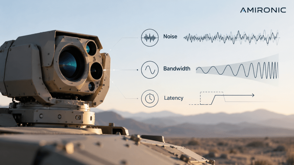
Three key parameters influence an IMU’s ability to meet these requirements:

  • Noise: Random fluctuations in the sensor output that limit the system’s ability to distinguish small, genuine movements from measurement noise.
  • Bandwidth: The range of frequencies over which the sensor can accurately track dynamic changes within a specified response tolerance.
  • Latency: The time between the occurrence of physical motion and the availability of the corresponding measurement data to the control system.

These parameters are closely related, and improving one may sometimes involve compromising another.

For example, aggressive digital filtering can significantly reduce measurement noise, but it may also introduce additional latency and limit the usable bandwidth. Conversely, increasing bandwidth allows the sensor to capture faster motio
Data Rate, Bandwidth, and Latency – Three Critical Parameters That Should Not Be Confused

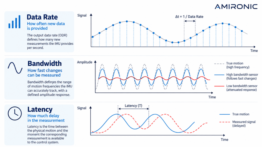
One of the most common mistakes when selecting an IMU for a high-speed control system is assuming that a high data output rate automatically means faster sensor response.

In reality, these are three distinct parameters, each describing a different aspect of sensor performance. Understanding their differences is essential when designing stabilization, navigation, and dynamic control systems.

1. Data Rate – How Frequently Does the Sensor Update?

The Output Data Rate (ODR) specifies how frequently a sensor provides new measurement data to the control system.

For example, a sensor operating at an output data rate of 10,000 Hz delivers 10,000 samples per second, corresponding to one sample every 100 microseconds.

However, this specification does not necessarily indicate how quickly the sensor responds to physical motion. A sensor may transmit data at a high rate while the measurements have undergone significant filtering or represent motion that occurred earlier.

In other words, a high data rate does not guarantee low latency or real-time responsiveness.

2. Bandwidth – How Fast Can the Sensor Track Motion?

Bandwidth describes the frequency range over which a sensor can track changes in motion while maintaining a specified amplitude response.

Consider a stabilization system installed on an off-road military vehicle, where the controller must compensate for vibration and rapid platform movement.

If the sensor’s bandwidth is insufficient relative to the relevant motion frequencies, some of these movements will be attenuated and will not be fully represented in the measurements delivered to the controller.

It is important to distinguish between sensor bandwidth and closed-loop control bandwidth.

Sensor bandwidth describes the frequency response of the measurement system. Closed-loop bandwidth depends on the complete control architecture, including the controller, actuators, mechanical structure, and accumulated delays.

Higher bandwidth also involves a trade-off. As the measured frequency range increases, the total measurement noise may increase, depending on the sensor’s noise density and filtering characteristics.

3. Latency – How Quickly Does the Measurement Reach the Controller?

Latency is the time between the occurrence of physical motion and the availability of the corresponding measurement data to the control system.

Potential sources of latency include internal filtering, signal processing, sample accumulation, data transmission, and communication with the controller.

In high-speed control applications, even a few milliseconds of latency can significantly affect system performance.

For example, a pure time delay of 1 millisecond at a motion frequency of 100 Hz introduces a phase lag of 36 degrees.

The phase shift caused by a pure time delay can be calculated as:

Phase shift (degrees) = -360 × Frequency (Hz) × Delay (seconds)

Where:

  • Frequency is the motion frequency in hertz.
  • Delay is the time delay in seconds.

Such a phase lag can reduce the available phase margin of a feedback control loop, making it more difficult to compensate for rapid motion and potentially increasing the risk of oscillation if the delay is not properly accounted for in the control design.

Practical Example: Two IMUs with the Same Data Rate

Consider two hypothetical IMU sensors operating at identical output data rates:

Parameter Sensor A Sensor B
Output Data Rate 10 kHz 10 kHz
Sensor Bandwidth 100 Hz 600 Hz
Measurement Latency 5 ms 0.5 ms
Output Sample Interval 0.1 ms 0.1 ms

Note: These values are illustrative and do not represent the specifications of any particular Gladiator Technologies product.

Although both sensors deliver the same number of samples per second, Sensor B supports a wider range of motion frequencies and provides measurements with significantly lower latency.

In a high-speed stabilization system, these differences may be far more important than the output data rate alone.

However, Sensor B is not necessarily the better choice for every application. If the control system operates primarily at lower frequencies and requires exceptionally low measurement noise, a sensor with narrower bandwidth may be more suitable, depending on its noise characteristics and filtering architecture.

The engineering takeaway: An IMU should never be selected based on data rate alone. Bandwidth, latency, noise performance, and filtering characteristics must be evaluated together against the dynamic requirements of the application.

Measurement Noise – Why Can an Extremely Fast IMU Compromise Control System Performance?

Having examined the differences between Data Rate, Bandwidth, and Latency, we must consider another critical factor affecting control system performance: measurement noise.

Every inertial sensor produces random fluctuations in its output, even when completely stationary. These fluctuations may originate from the sensing element itself, electronic circuitry, sampling processes, and signal processing.

In navigation systems, measurement noise can contribute to accumulated errors in estimated position and orientation. In high-speed stabilization systems, the effects may be more immediate: the controller may interpret part of the noise as actual motion and generate unnecessary correction commands.

Depending on the control architecture, this can result in unwanted micro-movements (jitter), increased actuator activity, and reduced tracking accuracy.

The engineering challenge is to provide the controller with fast, accurate motion information without introducing excessive measurement noise or adding significant latency through aggressive digital filtering.

Understanding the Relationship Between Noise Density and Bandwidth

One of the most important specifications for evaluating inertial sensor noise performance is Noise Density.

Noise density describes the amplitude of random measurement noise relative to the square root of bandwidth. Lower noise density generally allows cleaner measurements over the same frequency range.

However, bandwidth and total measurement noise are closely related. Increasing bandwidth enables the sensor to capture faster motion, but it typically also increases the total noise passed to the control system.

For example, increasing the equivalent noise bandwidth from 100 Hz to 400 Hz doubles the RMS noise, assuming constant white-noise density.

This relationship illustrates why improving control system performance does not necessarily mean reducing bandwidth. A sensor with inherently lower noise density may provide a better balance between measurement quality and dynamic response.

This is particularly relevant when evaluating advanced inertial sensing platforms such as Gladiator Technologies’ SX3.

SX3 – A New Generation of Low-Noise Inertial Sensing

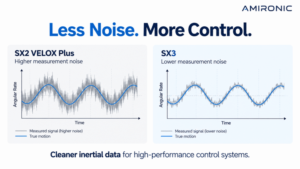
Gladiator Technologies’ SX3 represents a newer generation of the company’s inertial sensing technology, with an emphasis on improved measurement noise performance.

While SX2 VELOX Plus addresses applications requiring high output data rates and fast dynamic response, SX3 places additional emphasis on measurement quality, particularly noise reduction.

The importance of improved noise performance extends beyond static accuracy. In stabilization and tracking applications, cleaner measurements help the controller distinguish genuine motion from random sensor fluctuations.

Depending on the sensor configuration and overall system design, lower measurement noise can offer several potential engineering benefits:

  • Improved stabilization accuracy: Lower noise entering the feedback loop may reduce unnecessary correction commands and unwanted micro-movements.
  • Better dynamic measurement capability: Lower noise density can help maintain measurement quality over a wider frequency range.
  • Reduced filtering requirements: Cleaner sensor output may allow less aggressive filtering, potentially reducing the latency introduced by signal processing.
  • Improved tracking performance: More accurate detection of small angular movements may improve line-of-sight stability in electro-optical systems.

It is important to distinguish between reduced measurement noise and reduced sensor latency. A lower noise density does not automatically mean that the sensor itself has a shorter internal delay.

The potential advantage lies in the additional flexibility available to the control system designer when balancing noise, bandwidth, and filtering requirements.

The actual performance difference between SX2 VELOX Plus and SX3 should be evaluated using the specifications of the relevant sensor models under comparable measurement conditions.

Numerical Example – What Does Lower Noise Actually Mean?

Consider two hypothetical gyroscopes operating with the same equivalent noise bandwidth of 400 Hz.

The first gyroscope has a noise density of 0.005 degrees per second per square root of hertz, while the second has a noise density of 0.002 in the same units.

Assuming constant white-noise density across the measurement bandwidth, the theoretical results are:

  • Sensor A: RMS noise of 0.100 degrees per second.
  • Sensor B: RMS noise of 0.040 degrees per second.
  • Result: A 60% reduction in RMS noise without changing the equivalent noise bandwidth.

These figures are illustrative only and do not represent published specifications or measured performance of SX2 or SX3.

In a stabilization system, this difference may be significant. Cleaner angular rate measurements can help the controller distinguish actual platform motion from random measurement noise.

This demonstrates the engineering value of lower-noise inertial sensing: the possibility of maintaining fast dynamic measurement capability while reducing the noise delivered to the control system.

Additional Examples – Gladiator Technologies Accelerometers

The relationship between measurement range, noise density, and bandwidth can also be illustrated using Gladiator Technologies’ accelerometer families.

The company offers both open-loop and closed-loop accelerometer technologies designed for different acceleration ranges and performance requirements.

GA50 – Low-Noise Acceleration Measurement

The GA50 is a single-axis analog MEMS accelerometer based on an open-loop sensing architecture.

For the ±5 g measurement range version, the manufacturer’s specifications include:

  • Noise Density: 1.3 micro-g per square root of hertz.
  • Bandwidth: Greater than 250 Hz.
  • Short-Term Bias Stability: 60 micro-g.
  • Long-Term Bias Repeatability: 0.8 milli-g.
  • Dimensions: 8.9 × 8.9 × 3.2 mm.

Assuming constant white-noise density and an equivalent noise bandwidth of 250 Hz, the calculated RMS noise is approximately 20.6 micro-g.

This is a theoretical estimate, not a directly measured noise value. The actual result depends on the sensor’s frequency response, filtering characteristics, and equivalent noise bandwidth, which is not ne

How Do Noise and Latency Affect Electro-Optical Stabilization Performance?

One of the applications where the need for a fast, low-noise IMU becomes particularly important is electro-optical stabilization.

These systems are commonly installed on military vehicles, unmanned aerial vehicles (UAVs), naval platforms, and mobile surveillance systems. Their purpose is to maintain a stable line of sight even when the platform itself is moving.

For example, when a military vehicle travels over rough terrain, its electro-optical system is exposed to changes in orientation, vibration, and acceleration. The IMU measures the platform’s motion and provides data to the controller, which commands the actuators to compensate for unwanted movement.

However, stabilization quality depends not only on sensor accuracy but also on how quickly the measurements reach the controller and how much noise they contain.

Numerical Example – The Impact of Latency on Control Performance

Consider a stabilization system whose controller must respond to motion at a frequency of 100 Hz.

Compare two hypothetical sensor configurations:

  • Sensor A: Measurement latency of 5 milliseconds.
  • Sensor B: Measurement latency of 0.5 milliseconds.

At 100 Hz, a pure time delay of 5 milliseconds introduces a phase lag of 180 degrees, while a delay of 0.5 milliseconds introduces a phase lag of only 18 degrees.

This means that Sensor A may provide information corresponding to a substantially earlier phase of the motion cycle, while Sensor B delivers more timely measurements.

This does not automatically mean that a system using Sensor A will be unstable. Closed-loop stability depends on the complete control architecture, including the controller, actuators, mechanical dynamics, and other sources of delay.

Nevertheless, additional latency reduces the available phase margin at a given frequency and can limit achievable control bandwidth.

This example demonstrates why latency is a critical consideration in high-speed stabilization systems, even when both sensors provide data at high output rates.

Note: These values are illustrative and do not represent published latency specifications for SX2 VELOX Plus or SX3.

The Role of SX3 in Dynamic Control Applications

Gladiator Technologies’ SX3 platform emphasizes improved inertial measurement noise performance, an important consideration in advanced dynamic control systems.

In high-speed stabilization applications, lower noise density can improve the detection of small movements while the system operates under demanding dynamic conditions.

This capability is particularly relevant in three application areas.

1. Line-of-Sight Stabilization

In electro-optical surveillance systems, unwanted angular motion can cause image displacement and reduce tracking accuracy.

When gyroscope measurements contain significant noise, the controller may respond to fluctuations that do not represent actual platform movement.

Lower-noise inertial measurements can help reduce unnecessary correction commands and improve line-of-sight stability, depending on the control architecture and system dynamics.

The emphasis on improved noise performance in SX3 makes this an important consideration when evaluating the platform for precision stabilization applications.

2. Unmanned Platforms

Unmanned aerial, ground, and maritime systems frequently operate in environments characterized by motor vibration, rapid directional changes, and varying motion conditions.

These applications require inertial sensors capable of capturing genuine platform movement without introducing excessive measurement noise into the control system.

SX3 provides a technology platform for considering low-noise inertial measurements in such applications, with sensor bandwidth and filtering selected according to the specific system requirements.

Actual performance must also account for environmental vibration, mechanical integration, and the relevant sensor configuration.

3. Precision Tracking and Motion Control Systems

In precision tracking applications, the controller must distinguish actual changes in position or angular velocity from random measurement fluctuations.

Excessive measurement noise may generate unnecessary correction commands, increase actuator activity, and reduce tracking accuracy, depending on the characteristics of the feedback loop.

Using an inertial sensor with lower noise density can reduce the contribution of measurement noise to control error and support more precise tracking performance.

How to Select an IMU for High-Speed Control Systems

Selecting an IMU should never depend on a single specification.

Engineers designing stabilization or dynamic control systems should evaluate several parameters together:

Output Data Rate (ODR): Does the sensor provide measurement updates at a rate compatible with the control loop and communication interface?

Bandwidth: Can the sensor capture the relevant motion frequencies without excessive signal attenuation?

Latency: How much time passes between physical motion and the availability of the measurement, and how does this delay affect the control loop’s phase margin?

Noise Density: What is the sensor’s noise level, and how does it contribute to total RMS noise over the required equivalent noise bandwidth?

Bias Stability: How stable is the sensor’s zero-rate or zero-acceleration output over time and under changing temperature conditions?

Environmental Durability: Can the sensor withstand the expected vibration, shock, and operating temperature conditions?

In high-speed control applications, understanding the relationship between these parameters is more important than evaluating each specification independently.

For example, a sensor with high bandwidth may be less suitable if aggressive filtering is required to achieve the necessary noise performance.

Conversely, a sensor with inherently low noise density may allow less aggressive filtering, potentially reducing the additional latency introduced by signal processing.

This engineering trade-off is particularly relevant when evaluating newer low-noise inertial sensing technologies such as SX3.

SX3 – From Motion Measurement to Improved Control Performance

The evolution of IMU technology is no longer focused solely on increasing sampling rates or improving static accuracy.

A central challenge in advanced control systems is delivering clean, fast, and timely inertial data that enables the controller to respond to actual motion while minimizing the effects of noise and delay.

Gladiator Technologies’ SX2 VELOX Plus provides an established platform for applications requiring fast inertial measurements. The newer SX3 platform places additional emphasis on noise performance, offering control system designers further opportunities to optimize measurement quality.

The potential benefit of low-noise sensing is not simply a smoother output signal. It is the ability to balance measurement quality with the dynamic requirements of the application.

In electro-optical stabilization, unmanned platforms, and precision tracking systems, properly balancing Noise, Bandwidth, and Latency can contribute significantly to control accuracy, stability, and responsiveness.

Frequently Asked Questions (FAQ)

Does a Higher Data Rate Mean a Faster IMU?

Not necessarily. Data Rate describes how frequently the sensor provides updated measurements, but it does not directly indicate sensor bandwidth or measurement latency.

An IMU may deliver thousands of samples per second while those measurements have undergone filtering or processing that introduces additional delay.

What Is the Difference Between Bandwidth and Latency in an IMU?

Bandwidth describes the range of motion frequencies that the sensor can measure within a specified response tolerance.

Latency describes the time between physical motion and the availability of the corresponding measurement data.

Both affect dynamic performance, but they represent different characteristics and must be evaluated separately.

Why Is Low Noise Important in Stabilization Systems?

Measurement noise can cause a controller to interpret random sensor fluctuations as actual motion.

Depending on the control system, this may lead to unnecessary actuator corrections, unwanted micro-movements, and reduced stabilization accuracy.

Lower sensor noise can improve measurement quality and reduce the contribution of random fluctuations to control error.

Does Increasing IMU Bandwidth Always Improve Performance?

No. Higher bandwidth allows the sensor to capture faster motion, but it generally increases total measurement noise when noise density remains constant.

The appropriate bandwidth should be selected according to the relevant motion frequencies, noise requirements, and control system design.

What Is the Main Advantage of SX3 Compared with SX2 VELOX Plus?

Gladiator Technologies’ SX3 platform places particular emphasis on improved inertial measurement noise performance.

Lower noise density can potentially improve the detection of small movements, reduce dependence on aggressive filtering, and improve the quality of information available to the controller.

Any quantitative performance comparison between SX2 VELOX Plus and SX3 should be based on the specifications of the relevant models under equivalent measurement conditions.

Does Lower Noise Automatically Mean Lower Latency?

No. Noise and latency are separate performance parameters.

However, a sensor with lower inherent noise may allow the system designer to use less aggressive filtering, potentially reducing the delay introduced by signal processing.

This does not necessarily change the sensor’s internal measurement latency.

Which Applications Benefit Most from Low-Noise IMUs?

Low-noise inertial sensors are particularly relevant to electro-optical stabilization systems, unmanned platforms, navigation systems, precision tracking mechanisms, and dynamic control applications where distinguishing actual motion from measurement noise is essential.

Technical Glossary

IMU – Inertial Measurement Unit: A sensing unit that typically combines accelerometers and gyroscopes to measure acceleration and angular motion.

Data Rate / ODR (Output Data Rate): The frequency at which a sensor provides updated measurement data.

Bandwidth: The frequency range over which a sensor can track changes in the measured signal within a specified response tolerance.

Latency: The delay between physical motion and the availability of the corresponding measurement.

Noise Density: A measure of sensor noise amplitude relative to the square root of measurement bandwidth, typically expressed in units per square root of hertz.

RMS Noise (Root Mean Square Noise): A measure of the effective noise amplitude over a defined frequency range.

Bias Stability: A measure of how consistently a sensor maintains its zero-input output over time or under specified conditions.

Jitter: Small, unwanted fluctuations in a measured signal or in the response of a control system.

Closed-Loop Control: A control architecture that uses feedback to compare the desired system state with the measured state and generate corrective commands.

Line-of-Sight Stabilization: The process of maintaining the pointing direction of an optical or electro-optical system despite movement of its supporting platform.

Conclusion

Selecting an IMU for a high-speed control system requires looking beyond static accuracy and output data rate.

Measurement noise, bandwidth, and latency collectively influence the quality of information available to the controller, the stability margins of the feedback loop, and the system’s ability to respond accurately to dynamic motion.

Gladiator Technologies’ SX3 platform highlights the importance of low-noise inertial sensing in the development of advanced stabilization and control systems.

In high-speed control applications, the goal is not simply to measure faster, but to deliver cleaner motion data at the right time.

Amironic, the Israeli representative of Gladiator Technologies, supports engineers and system designers in selecting IMUs, gyroscopes, and accelerometers according to the dynamic, environmental, and system-level requirements of their applications.

For additional technical information, product specifications, or assistance evaluating SX3 for your application, contact the Amironic engineering team.

Tags: Gladiator_Technologies

Related Articles

The IMU Was Excellent. The Image Still Shook.

01/06/2026amironicLTD

Why Position Feedback Matters More Than Ever in Counter-UAS Swarm Defense

02/08/2026amironicLTD

2000Hz IMU? Before You Get Impressed, Understand Three Completely Different Numbers

07/06/2026amironicLTD

Recent Posts

  • IMU Sensors for High-Speed Control Systems – Balancing Noise, Bandwidth, and Latency
  • Inertial Sensors in Loitering Munitions and Unmanned Systems – Engineering Challenges Beyond the Datasheet
  • Medical Footswitches – Precision Control, Modular Design and UL 60601-1 Certification
  • 5 mm Shaft & Bearing – Worm Gear Fits and Tolerances
  • Filter Monitoring in Fume Extraction Systems – Detecting Filter Clogging with Pressure & Vacuum Switches

Categories

  • Air Switch
  • Circuit Breakers
  • Elapsed Time Indicator
  • Feedthrough
  • Footswitches
  • Gears & Transmission
  • Hour Meters
  • Infra Red Switches
  • INFRARED LAMPS
  • Low Noise Inertial MEMS
  • Mechanics
  • MEMS Gyroscope
  • MEMS Inertial
  • Microelectronics
  • Motors
  • Position Sensors
  • Power Supply
  • Pressure Sensors
  • Pressure Switch
  • Switches
  • Temperature Sensors
  • Tungsten and Molybdenum
  • Uncategorized
  • Vacuum Switches

Quick Contact

Fill out the form and our representatives will return to you

    Name (required)

    Email (required)

    Phone

    Message

    This site is protected by reCAPTCHA and the Google
    Privacy Policy and
    Terms of Service apply.

    Amironic Ltd.

    3 Rabinovich Street, Petah Tikva 4928144 , Israel. Tel: +972-3-9047744 E-mail: office@amironic.co.il
    Email
    Facebook
    Twitter
    LinkedIn
    YouTube
    Press on the ISO Certificate below for download
    ISO 9001:2015 Certification
    • MEMS Inertial
    • Circuit Breakers
    • Footswitches
    • Mechanical & Transmisions
    • Sensors
    • Motors
    • Electronics
    • Hand Control
    • Power Solutions

    News

    • IMU Sensors for High-Speed Control Systems – Balancing Noise, Bandwidth, and Latency
    • Inertial Sensors in Loitering Munitions and Unmanned Systems – Engineering Challenges Beyond the Datasheet
    • Medical Footswitches – Precision Control, Modular Design and UL 60601-1 Certification
    • 5 mm Shaft & Bearing – Worm Gear Fits and Tolerances
    • Filter Monitoring in Fume Extraction Systems – Detecting Filter Clogging with Pressure & Vacuum Switches
    About AmironicContactעברית
    © 2022 Amironic All rights reserved. All Trademarks are the property of their respective owners.
    • Increase Font
    • Decrease Font
    • Black & White
    • Inverse Colors
    • Highlight Links
    • Regular Font
    • Reset