flagעברית
flagEnglish
3 Rabinovich St., Petah-Tikva, Israel
+972 3 9047744
office@amironic.co.il
Facebook
Twitter
LinkedIn
YouTube
  • Products
    • MEMS Inertial
      • MEMS Gyroscopes
      • Inertial Measurement Units
      • MEMS Accelerometers
      • Inertial Navigation
      • AHRS
    • Circuit Breakers
      • Airpax Circuit Breakers
      • Electronic Circuit Breakers
      • Aircraft Circuit Breakers
      • Thermal Circuit Breakers
      • Sealing Solutions & Guards
    • Footswitches
      • Pedals & Bellows
      • USB
      • Air Switches
      • Medical
      • Modular Bases System
      • Industrial
      • Foot Potentiometers
      • Wireless
    • Mechanical & Transmissions
      • Gears
      • Sealing Solutions
      • Gearboxes
      • Couplings
      • Shafts & Bearings
      • Fasteners
      • Mechanical & Springs
      • Linear Motion
      • Anti-Vibration
    • Sensors
      • Thermostats
      • Temperature
      • Position
      • Pressure
      • Speed
      • Level Sensor
      • Load Cells
      • Flex Sensors
      • Membrane Potentiometer
    • Motors
      • Geared DC
      • Brushless DC
      • Step Motors with Gearbox
      • Torque Motors & Brushless Servo
      • DC Motors
    • Electronics
      • Xenon & IR Lamps
      • Counters & Meters
      • Microelectronics Packaging
      • Waterproof Switches
      • Micro Switches
    • Hand Control
      • Operator Controls (JOYSTICK)
      • Electrical
      • Pneumatic (Medical)
      • USB Hand Control
      • Air Push Button
      • Pressure Switch
      • IR Switch
    • Power Solutions
      • Rugged & Military Power Supply
      • Input Power Protection
      • Sealed Military Power Adaptor
      • Triple Output Military Power Supply Series – up to 250 W
    • Materials
      • Molybdenum and Advanced Alloys (TZM, MOLA, HCT)
      • Tungsten (Wolfram) and Advanced Alloys – High-Performance Materials for Extreme Conditions
      • Materials for Gears
  • Shop
  • Companies
  • About Amironic
  • News
  • Contact
Product was added to your cart

Cart

waze

Footswitches in Medical Imaging Systems and Surgical Robotics – Hands-Free Operation, Ergonomics, and Precision Control

Footswitches10/11/2026amironicLTD

1. Introduction – Why Have Footswitches Become Important Components in Advanced Medical Equipment?

In modern medical environments, where imaging systems, diagnostic equipment, surgical robotics, and advanced treatment technologies often operate simultaneously, the ability to control various functions without using the hands provides a significant operational advantage.

Physicians, surgeons, imaging technicians, and other healthcare professionals frequently need to operate equipment while maintaining precise instrument positioning, holding medical tools, working in sterile environments, or continuously monitoring patients.

In these situations, a medical footswitch allows operators to activate specific functions using their feet without interrupting tasks performed with their hands.

Footswitches are used in a wide range of medical systems, including:

  • Medical Imaging Systems.
  • Ultrasound Systems.
  • X-ray and Fluoroscopy Systems.
  • Surgical Robotics.
  • Electrosurgical Equipment.
  • Transcranial Magnetic Stimulation (TMS) Systems.
  • Automated Medical Systems and Advanced Diagnostic Equipment.

Although a footswitch is a relatively small component within a complete medical system, selecting the appropriate device can influence operator comfort, workflow continuity, operational reliability, and the management of operational risks.

HERGA Technology, a British manufacturer represented in Israel by Amironic, offers a broad range of foot-operated control solutions, including electrical footswitches, pneumatic footswitches, and solutions designed for integration into OEM systems.

In this article, we examine the key engineering considerations when selecting a footswitch for medical equipment, explore common applications, and discuss the important factors involved in integrating footswitches into medical imaging systems, surgical robotics, and advanced therapeutic equipment.


2. Hands-Free Operation in Medical Imaging Systems

2.1 Operational Challenges in Medical Imaging

Medical imaging systems provide visual information that supports diagnosis, treatment, and image-guided medical procedures.

In certain applications, operators must perform several tasks simultaneously:

  • Hold or position a medical instrument.
  • Maintain the position of a patient or sensor.
  • Monitor images displayed on a screen.
  • Activate a specific system function.
  • Maintain workflow continuity and appropriate operating conditions.

When every function requires a manual button, keyboard, or touchscreen, the operator may need to release an instrument or change their working position.

A footswitch makes it possible to separate tasks performed with the hands from commands issued using the foot.

This enables the design of a Human-Machine Interface (HMI) that better supports the requirements of the medical procedure.

2.2 Footswitches in Ultrasound Systems

During an ultrasound examination, the physician or technician holds an ultrasound transducer and positions it against the patient’s body.

At the same time, the operator may need to activate functions such as:

  • Image freeze.
  • Image or image-sequence capture.
  • Start or stop recording.
  • Switching between predefined operating modes.

When the ultrasound system supports a suitable interface, some of these functions can be assigned to a footswitch.

The main advantage is that the operator can maintain the transducer in the desired position without moving a hand to the control panel.

For example, during an examination requiring an image to be captured at a particular moment, the system can be designed so that pressing a footswitch triggers an image-save command.

However, it is important to distinguish between the footswitch and the system software: the footswitch provides an activation signal, while the system interprets that signal and executes the assigned function.

2.3 Footswitches in X-ray and Fluoroscopy Systems

In X-ray and fluoroscopy equipment, footswitches may be integrated into the system’s operator interface.

In certain applications, a foot pedal is used to activate a function associated with the imaging process, subject to the equipment’s control architecture and safety requirements.

For example, a fluoroscopy system may incorporate a foot-operated interface that allows the operator to control a designated function while continuing to handle other medical instruments.

Safety-related design considerations are particularly important in these applications:

  • Prevention of unintended activation.
  • Defined system behavior when the pedal is released.
  • Detection of faults in the footswitch or its connection.
  • Prevention of activation caused by electrical faults.
  • Integration of additional protective measures based on the system’s risk analysis.

Important: A footswitch does not, by itself, constitute a radiation safety system. Any function affecting radiation generation must be integrated into the safety architecture and regulatory requirements applicable to the complete imaging system.

2.4 What About MRI Systems?

Hands-free operation may also be desirable in MRI systems, but MRI environments introduce unique constraints.

Strong magnetic fields, electromagnetic interference, and compatibility requirements within the scanner environment require individual evaluation of every component.

A footswitch suitable for ultrasound equipment or general medical applications should not automatically be considered suitable for use in an MRI room.

Such suitability requires evaluation of the device’s construction, materials, cables, intended location, and applicable MR safety classification.


3. Footswitches in Surgical Robotics

3.1 Why Do Surgical Robotic Systems Need Additional Control Interfaces?

Surgical robotic systems allow surgeons to control medical instruments through advanced control interfaces.

During a surgical procedure, the surgeon’s hands may be occupied with instrument manipulation, precise movements, or operation of a robotic control interface.

In these situations, a footswitch provides an additional command interface without requiring more functions to be assigned to hand-operated controls.

Depending on the system design, a footswitch may be used to select a function, activate an operating mode, or control another designated operation.

This can help maintain workflow continuity and reduce the need to switch between control interfaces.

3.2 Deterministic Control

One of the important concepts in robotic system design is deterministic control.

This refers to predictable and well-defined control-system behavior, including the timing of responses to operator commands.

When a surgeon presses a foot pedal, the system should detect and process the event consistently and in accordance with its design requirements.

However, three distinct stages must be considered:

  1. Detection of the pedal press by the footswitch.
  2. Transmission of the signal to the system controller.
  3. Processing of the command and execution of the operation by the robotic system.

The overall response depends on the entire control chain, not just the footswitch.

3.3 Low-Latency Operation

In advanced medical systems, the response time between an operator’s action and the system’s reaction can be an important design parameter.

For example, when a footswitch activates a robotic function, the total response delay should be evaluated:

Total Response Time = Switch Response + Signal Processing + Communication + Controller Response + Actuation

In certain systems, excessive or inconsistent latency may negatively affect the operator’s sense of control.

Therefore, system designers should define requirements for response time, timing variability (jitter), and behavior under fault conditions.

Low latency should not be assumed simply because a particular mechanical or electrical switch has been selected. The complete system must be evaluated.

3.4 Ergonomics, Precision, and Prevention of Unintended Activation

In surgical environments, pedal placement and footswitch construction are just as important as the electrical interface.

Key considerations include:

  • Required actuation force.
  • Pedal travel.
  • Tactile feedback during activation.
  • Stability of the footswitch on the floor.
  • Resistance to slipping during operation.
  • Compatibility with medical footwear.
  • Clear identification when multiple pedals are present.
  • Protection against accidental activation.

In systems incorporating multiple pedals, designers should also evaluate the spacing between them and the operator’s ability to distinguish different functions through pedal position, shape, or tactile feedback.

Proper ergonomic design can help reduce operating errors and improve user comfort during lengthy medical procedures.

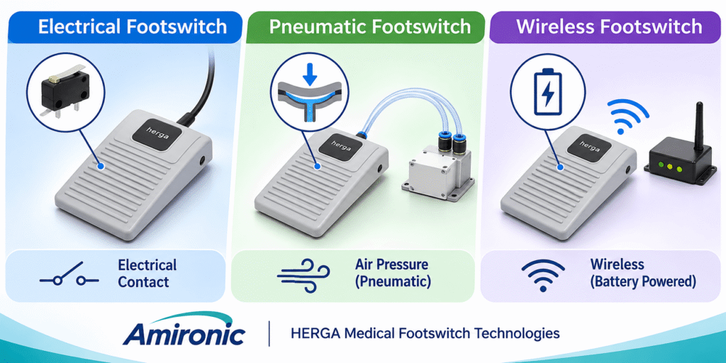
Footswitches in medical imaging systems and surgical robotics – hands-free operation that enables healthcare professionals to maintain equipment control, workflow continuity, and operational precision.

4. Footswitch Technologies for Medical Equipment – Electrical, Pneumatic, and Wireless

Selecting a footswitch for a medical system involves much more than pedal design or operating comfort.

One of the most important engineering considerations is how the activation command is transmitted to the control system.

Three main approaches are commonly used in medical equipment:

  • Electrical Footswitches.
  • Pneumatic Footswitches.
  • Wireless Footswitches.

Each technology offers different advantages, limitations, and integration considerations.

4.1 Electrical Footswitches

An electrical footswitch typically uses a switching mechanism activated by pressing a foot pedal.

When the operator presses the footswitch, the electrical contacts change state, allowing the system to detect an activation signal.

Depending on the switch design, different contact configurations may be available:

  • Normally Open (NO): The contact is open in its normal resting state and closes when activated.
  • Normally Closed (NC): The contact is closed in its normal resting state and opens when activated.
  • Single Pole Double Throw (SPDT): A changeover contact configuration that switches between two electrical paths.

The selection of contact configuration depends on the control logic, system requirements, and risk analysis.

For example, an ultrasound system may use a footswitch connected to a digital input on its controller.

When the pedal is pressed, the controller detects the input-state change and activates a predefined function, such as freezing or saving an image.

Key advantages:

  • Relatively straightforward integration with electronic controllers.
  • Direct connection to compatible digital inputs.
  • A wide range of contact configurations and operating mechanisms.
  • No battery required for a passive electrical footswitch.
  • Suitability for a broad range of OEM applications.

However, designers must evaluate contact ratings, mechanical and electrical service life, suitability for low-level signal switching, and the required protection against liquid ingress.

In systems using extremely low-current control signals, it is particularly important to verify that the contacts are suitable for the operating conditions. A contact designed for switching higher electrical loads is not necessarily the best choice for a very low-current control circuit.

4.2 Pneumatic Footswitches

A pneumatic footswitch operates by generating a change in air pressure rather than switching electrical contacts inside the pedal.

In a typical pneumatic system, pressing the pedal produces a pressure change that travels through flexible tubing to a separate pneumatic-to-electrical switching unit.

The switching unit can be positioned away from the pedal, depending on the system architecture.

This arrangement separates the mechanical activation point from the electrical switching components.

Potential advantages of pneumatic operation include:

  • Physical separation between the foot pedal and the electrical switching contacts.
  • The ability to position electrical switching components in a protected location.
  • Greater design flexibility where electrical components are restricted near the operating area.
  • Potential suitability for environments involving moisture or cleaning, subject to the specific product construction.

For example, in medical equipment where the pedal is located in an area exposed to liquids, a pneumatic solution may be considered to allow electrical switching to take place elsewhere.

However, a pneumatic footswitch is not automatically waterproof or approved for medical use simply because it operates pneumatically.

The enclosure protection rating, construction materials, tubing compatibility, connections, and switching-unit characteristics must all be evaluated.

Pneumatic systems also require consideration of tubing length, internal volume, possible air leakage, and actuation-force requirements.

These factors may influence pedal feel and the dynamic response of the system.

4.3 Wireless Medical Footswitches

In some medical environments, cables running across the floor can restrict movement, complicate equipment arrangement, or create operational challenges.

Wireless footswitches transmit commands through a wireless communication link rather than a signal cable directly connected to the pedal.

Depending on the product and system, communication may use Bluetooth Low Energy (BLE) or another wireless technology.

Potential advantages include:

  • Fewer signal cables in the operating area.
  • Greater flexibility in pedal positioning.
  • Easier reconfiguration of the working environment.
  • More convenient integration into certain mobile medical systems.

However, wireless solutions introduce additional engineering considerations:

  • Response time and timing variability.
  • Wireless-link reliability.
  • Electromagnetic interference.
  • Communication security and device pairing.
  • Battery condition and maintenance.
  • System behavior during communication loss.
  • Prevention of unexpected activation when the connection is restored.

In medical systems where an activation command has safety implications, wireless technology must be evaluated as part of the overall system risk-management process.

4.4 Engineering Comparison of Footswitch Technologies

Feature Electrical Pneumatic Wireless
Operating principle Electrical contact switching Air-pressure change Wireless command transmission
System connection Electrical cable Pneumatic tubing and separate switching unit Receiver or communication interface
Electrical switching contacts inside pedal Typically yes No – switching occurs in a separate unit Depends on pedal design
Battery required in pedal Typically no No Typically yes
Positioning limitations Cable length Tubing length and characteristics Communication range and signal reception
Maintenance considerations Contacts and cable Tubing, sealing, and switching unit Battery and wireless communication
Special design considerations Contact ratings and input protection Leakage and pneumatic response Latency, connection reliability, and security

The choice between these technologies should be based on the requirements of the application rather than assuming that one technology is universally superior.

In a stationary medical imaging system, an electrical footswitch may provide a simple and reliable solution.

Where separation between the activation point and electrical switching contacts is desirable, a pneumatic solution may be worth considering.

For mobile equipment or environments where cable management is a significant concern, wireless operation may be relevant.


5. Hygiene, Cleaning, and Environmental Protection in Medical Footswitches

5.1 Why Do Medical Environments Have Special Requirements?

Footswitches are typically positioned at floor level, where they may be exposed to cleaning liquids, disinfectants, dust, and dirt.

In treatment rooms, medical laboratories, and operating rooms, equipment may undergo frequent cleaning and disinfection procedures.

Therefore, selecting a medical footswitch requires consideration not only of its electrical or mechanical operation but also of its external construction and long-term maintainability.

Key considerations include:

  • Enclosure design and the number of openings or crevices.
  • Compatibility of enclosure materials with intended cleaning agents.
  • Resistance to liquid ingress.
  • Cable and connector durability.
  • Accumulation of dirt around joints and moving parts.
  • Long-term durability of markings and labels.

5.2 IP Protection Ratings – What Do They Actually Guarantee?

One of the most common parameters used to evaluate environmental protection is the Ingress Protection (IP) rating, defined by IEC 60529.

This rating describes the degree of protection provided by an enclosure against the ingress of solid objects and water under specified test conditions.

For example:

Rating General Meaning
IP54 Dust-protected and protected against splashing water
IP65 Dust-tight and protected against water jets
IP67 Dust-tight and protected against temporary immersion under specified conditions
IP68 Dust-tight and protected against immersion under conditions specified by the manufacturer

It is important to understand that an IP rating does not necessarily indicate resistance to disinfectants, repeated cleaning, or chemical exposure.

For example, an IP67-rated footswitch is not automatically suitable for cleaning with every medical disinfectant.

Such compatibility also depends on enclosure materials, seals, cables, and actual operating conditions.

5.3 Chemical Resistance and Cleaning Agents

Medical equipment may be exposed to cleaning and disinfection products containing alcohol, quaternary ammonium compounds, and other active substances.

Repeated exposure to these chemicals may affect certain plastics, elastomers, coatings, and adhesives.

Therefore, medical equipment designers should obtain manufacturer information regarding the compatibility of footswitch materials with the intended cleaning protocol.

Exposure duration, chemical concentration, operating temperature, and cleaning frequency should also be considered.

A general description such as “suitable for medical environments” should not replace verification against actual operating conditions.

5.4 Slip Prevention and Floor Stability

A footswitch may move during operation if the applied force is unbalanced or if friction between the pedal and the floor is insufficient.

In medical environments, unwanted pedal movement can make the footswitch harder to locate quickly or increase the risk of unintended activation.

Important considerations include:

  • Footswitch base design.
  • Anti-slip surfaces or rubber feet.
  • Footswitch weight.
  • Direction of the applied force.
  • Cable routing and its effect on pedal stability.
  • Compatibility with floor surfaces and operator footwear.

In systems where the operator must activate multiple functions, pedal positioning should be evaluated through usability testing under conditions representative of the actual working environment.


6. Integrating Footswitches into Medical Equipment – OEM Integration

6.1 The Footswitch as Part of the Control System

Medical equipment manufacturers do not select a footswitch solely as a standalone component.

The footswitch forms part of a larger system that includes electronic controllers, software, user interfaces, protective mechanisms, and, in some cases, actuators.

Therefore, the selection process should begin by defining the function the footswitch is intended to perform.

Key questions include:

  • Is the footswitch intended to generate a momentary command or change an operating state?
  • Is one pedal required, or are multiple pedals needed?
  • Should the command remain active for as long as the pedal is pressed?
  • What should happen when the pedal is released?
  • How will the system detect a cable or contact fault?
  • Is protection against accidental activation required?
  • Will the footswitch remain in a fixed position or be moved between workstations?

The answers influence the selection of the switching mechanism, electrical interface, and pedal construction.

6.2 Momentary Commands vs. Hold-to-Operate Functions

Two common command types can be distinguished in medical systems.

Momentary Command

Pressing the pedal generates an event detected by the system, for example, to save an image.

In this case, the system software can detect a contact-state transition and execute a single function.

Hold-to-Operate

In other applications, the function is intended to remain active only while the pedal is pressed.

For example, a system may be designed so that releasing the pedal causes a designated operation to stop.

However, a spring-return footswitch alone does not guarantee that the operation will stop safely.

The system’s behavior depends on its control logic, fault detection, and additional safety measures.

6.3 Debouncing – Preventing Incorrect Detection of Pedal Activations

In mechanical contact switches, the transition between open and closed states may involve several rapid electrical transitions caused by contact bounce.

If the controller does not handle this phenomenon, a single pedal press may be interpreted as multiple activation events.

In medical systems where a footswitch triggers a specific function, consistent detection of both pressing and releasing events is important.

Contact bounce can be addressed through hardware filtering, software filtering, or a combination of both.

However, filtering must be balanced against response-time requirements to avoid introducing unnecessary delays.

6.4 Cables, Connectors, and Customized OEM Configurations

In medical equipment development projects, mechanical and electrical compatibility with the system is just as important as selecting the pedal itself.

OEM manufacturers may need to specify:

  • Cable length.
  • Connector type.
  • Wiring configuration.
  • Number of switching circuits.
  • Cable exit position.
  • Pedal color or construction.
  • Function markings.
  • Pneumatic tubing length, diameter, and connection type, where applicable.
  • Packaging and traceability requirements.

Not every option is available for every model, and certain customizations may be subject to minimum order quantities or an engineering approval process with the manufacturer.

Interface requirements should be defined as early as possible in the development process to avoid mechanical and electrical design changes at later project stages.

6.5 Electrical Safety and Medical Standards

When integrating a footswitch into medical equipment, designers must consider the safety requirements applicable to the complete system.

One of the principal standards in this field is IEC 60601-1, which specifies general requirements for the basic safety and essential performance of medical electrical equipment.

Depending on the application, additional standards and procedures may be relevant, including:

  • IEC 60601-1-2: Electromagnetic compatibility (EMC).
  • ISO 14971: Risk management for medical devices.
  • IEC 62366-1: Application of usability engineering to medical devices.
  • IEC 62304: Medical device software life-cycle processes, where applicable.

It is important to distinguish between a component meeting specific requirements and the complete medical system complying with applicable standards.

Even when a footswitch is marketed for medical equipment, the system manufacturer must verify that its integration is suitable for the intended application and relevant regulatory requirements.

7. HERGA 6210-3958-1 – Pneumatic Footswitch for Medical Equipment and OEM Systems

One way to integrate hands-free operation into medical equipment is through a pneumatic footswitch, which transmits an activation command by generating a change in air pressure rather than switching electrical contacts inside the pedal.

British manufacturer HERGA Technology offers a range of pneumatic control solutions that allow the mechanical activation point to be separated from the electrical switching point.

One of the models available in Israel through Amironic is the HERGA 6210-3958-1, a pneumatic footswitch from the HERGA 6210 series.

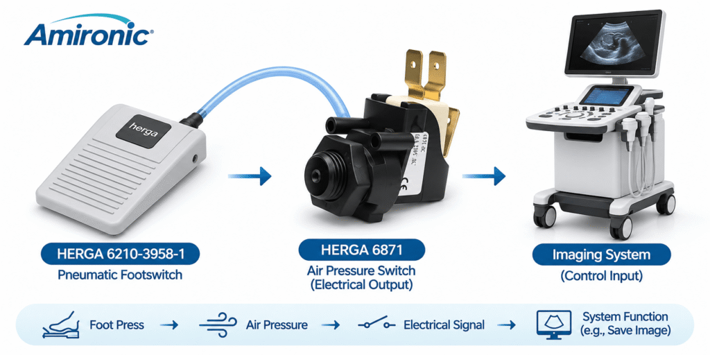
In suitable applications, this footswitch can be combined with a HERGA 6871 series air pressure switch, which converts the pneumatic pressure change into an electrical switching signal.

This arrangement enables medical equipment manufacturers and OEM designers to develop a control interface in which the foot pedal itself does not contain electrical switching contacts.

7.1 How Does a Pneumatic Footswitch Work?

The operating principle is based on generating a change in air pressure when the pedal is pressed.

A typical pneumatic control system involves four stages:

  1. Pedal activation: The operator presses the HERGA 6210-3958-1 footswitch.
  2. Pressure generation: A pneumatic mechanism inside the pedal produces a pressure change within the pneumatic circuit.
  3. Signal transmission: The pressure change travels through flexible air tubing to a HERGA 6871 series pressure switch.
  4. Electrical switching: The pressure switch responds to the pneumatic signal and changes the state of its electrical contacts according to its configuration.

The resulting electrical signal can be used as an input to a controller, control circuit, or another suitable system interface.

The activation sequence is:

Pedal Press → Air Pressure Change → Pneumatic Tubing → HERGA 6871 → Electrical Switching Signal → System Controller

It is important to understand that the pneumatic pedal does not transmit an electrical signal through the air tubing. The electrical switching signal is generated by the separate pressure-switch unit.

7.2 The Engineering Advantage – Separating the Pedal from Electrical Contacts

One of the main advantages of pneumatic operation is the ability to position electrical switching contacts away from the pedal’s operating area.

In a conventional electrical footswitch, the switching mechanism is typically located inside the pedal housing, with an electrical cable connecting it to the control system.

By contrast, in a pneumatic system based on the HERGA 6210-3958-1 and a compatible HERGA 6871 series switching unit, the pedal generates only a pneumatic pressure signal.

Electrical switching takes place at a separate location within the system.

This separation offers several potential design advantages:

  • Physical separation: Electrical switching contacts can be located away from the pedal’s operating environment.
  • Design flexibility: The switching unit can be installed inside the equipment enclosure or another protected location.
  • Suitability for challenging environments: Pneumatic operation may be considered where the pedal is exposed to moisture or liquids.
  • Electronic controller integration: The HERGA 6871 converts the pneumatic signal into an electrical signal suitable for integration into a control circuit.

However, pneumatic separation does not, by itself, establish compliance with medical electrical safety requirements or guarantee suitability for wet environments. The complete system must be evaluated, including the tubing, connectors, switching unit, and equipment enclosure.

7.3 The Role of the HERGA 6871 in the System

The HERGA 6871 series includes air pressure switches designed to respond to pneumatic pressure changes.

In a pneumatic footswitch system, the 6871 serves as the interface between mechanical-pneumatic activation and electrical control.

When the pressure change reaches the switching unit and meets its actuation requirements, the electrical contacts change state.

Depending on the selected configuration, these contacts can be integrated into the equipment’s control circuit.

When selecting a HERGA 6871 unit, designers should verify:

  • Operating pressure range and switching point.
  • Electrical contact configuration.
  • Voltage and current ratings.
  • Return-to-rest characteristics.
  • Compatibility with the pneumatic tubing.
  • Environmental and installation requirements.

The exact HERGA 6871 part number must be considered, as switching characteristics may vary between different configurations.

7.4 How Pneumatic Tubing Affects System Performance

Unlike an electrical footswitch, where the switching signal is transmitted through conductors, a pneumatic system transfers a pressure change through tubing.

Therefore, the tubing forms an integral part of the activation system, and its characteristics must be considered during design.

Important factors include:

Tubing Length: Longer tubing may affect the dynamic response, depending on the air volume and system characteristics.

Internal Diameter: Influences the internal air volume and resistance to airflow.

Tubing Flexibility: Expansion of the tubing under pressure changes may influence pneumatic signal transmission.

Connection Integrity: Air leaks can alter activation characteristics or prevent reliable detection of pedal operation.

Mechanical Routing: Sharp bends, crushing, and routing conditions that may damage or restrict the tubing should be avoided.

Consequently, when designing medical equipment with a pneumatic footswitch, the complete system should be tested using the intended tubing length and final installation configuration.

7.5 Potential Applications in Medical Equipment

A pneumatic footswitch combined with a pneumatic-to-electrical switching unit may be suitable for a variety of OEM applications, subject to the system’s requirements.

Potential applications include:

  • Ultrasound and medical imaging systems.
  • Therapeutic and diagnostic equipment.
  • Transcranial Magnetic Stimulation (TMS) systems.
  • Medical laboratory equipment.
  • Medical systems requiring separation between the activation area and electrical switching contacts.
  • Control systems requiring a foot-operated interface.

In every application, the components must be evaluated against the electrical, environmental, operational, and regulatory requirements of the complete system.


8. Pneumatic Footswitches in TMS Systems – Transcranial Magnetic Stimulation

8.1 Operational Challenges in TMS Systems

Transcranial Magnetic Stimulation (TMS) is a medical technology that uses time-varying magnetic fields to stimulate neural tissue.

During treatment, a magnetic coil is positioned near the patient’s head according to the treatment protocol.

In some systems, the operator must maintain the coil’s position while simultaneously controlling various equipment functions.

When the operator’s hands are occupied with positioning the coil, foot-operated control can provide an additional user interface.

8.2 Integrating a Pneumatic Control System

In a TMS system, designers may consider a pneumatic footswitch such as the HERGA 6210-3958-1, combined with a suitable switching unit from the HERGA 6871 series.

The system may operate as follows:

  1. The operator positions the coil according to the treatment requirements.
  2. Pressing the footswitch generates a pneumatic pressure change.
  3. The pressure change is transmitted to the switching unit.
  4. The HERGA 6871 changes the state of its electrical contacts.
  5. The TMS system controller detects the signal and determines whether to execute the assigned function.

A potential advantage of this arrangement is the ability to separate the pedal located near the operator from the electrical switching unit.

However, using a pneumatic footswitch does not automatically guarantee immunity to electromagnetic interference or suitability for every TMS environment. System behavior must be evaluated under actual operating conditions.

8.3 Safety and Design Requirements

In a therapeutic system, a footswitch signal should be treated as an operator command rather than independent authorization to perform a therapeutic action.

The system controller must verify that the required operating conditions have been satisfied.

For example:

  • The system is in an appropriate operating mode.
  • No fault condition prevents activation.
  • The treatment protocol has been configured as required.
  • The necessary safety conditions are satisfied.
  • The activation signal is correctly detected.

In addition, system behavior must be defined for conditions such as tubing leakage, pneumatic disconnection, switching-unit failure, or prolonged pedal activation.

The specific requirements depend on the TMS system architecture and its risk analysis.


9. Engineering Case Study – Integrating HERGA 6210-3958-1 and HERGA 6871 into a Medical Imaging System

9.1 Defining the Problem

Consider a design scenario involving an OEM manufacturer developing an ultrasound system for use in a medical treatment room.

During an examination, the physician holds the ultrasound transducer and occasionally needs to save an image displayed on the monitor.

In the original system, image capture is performed using a button on the control panel.

The manufacturer wants to introduce foot-operated control to reduce the need for the physician to move a hand away from the transducer.

Additionally, the engineering team wants to evaluate a solution in which the electrical switching contacts are located inside the equipment enclosure rather than inside the pedal.

This case study presents an illustrative engineering scenario and does not describe an actual commercial installation.

9.2 Proposed Solution

The proposed solution is based on two main components:

HERGA 6210-3958-1 – Pneumatic Footswitch

The foot-operated device serving as the physician’s activation interface.

HERGA 6871 – Air Pressure Switch

The switching unit that converts the pneumatic pressure change into a change in electrical contact state.

Suitable pneumatic tubing connects the two components.

The HERGA 6871 is connected to the ultrasound system’s control circuit.

9.3 Operating Sequence

When the physician wants to save an image:

  1. The physician presses the HERGA 6210-3958-1 footswitch.
  2. The pedal generates a pressure change in the pneumatic circuit.
  3. The pressure change travels through the tubing to the HERGA 6871.
  4. The pressure switch changes the state of its electrical contacts.
  5. The ultrasound controller detects the contact-state change.
  6. The system software executes the image-save command.

When the pedal is released, the pneumatic mechanism and electrical contacts return to their respective states according to the characteristics of the selected components and system configuration.

9.4 Integration Considerations

To ensure reliable operation, the engineering team must evaluate several parameters.

Parameter Engineering Consideration
Footswitch Mechanical and ergonomic suitability of the HERGA 6210-3958-1
Switching unit Selection of a suitable HERGA 6871 configuration
Pneumatic tubing Length, diameter, flexibility, and airtightness
Switching point Compatibility with the pressure change generated by the pedal
Electrical interface Compatibility of the HERGA 6871 contacts with the controller input
Response time Evaluation of the complete activation chain
Activation detection Prevention of duplicate or incorrect commands
Maintenance Inspection of connections, tubing, and switching unit
Safety Definition of system behavior under fault conditions

9.5 Recommended Verification Tests

After assembling the system, verification testing should be performed under conditions representative of the intended operating environment.

Press-and-Release Testing: Verify that the system detects pedal activation and release according to the design requirements.

Repeated Activation Testing: Evaluate switching consistency over multiple operating cycles.

Tubing Length Testing: Confirm that the system response remains acceptable with the selected tubing configuration.

Leakage and Disconnection Testing: Evaluate system behavior when the pneumatic signal is compromised.

Response Time Testing: Measure the total time between pedal activation and command detection by the controller.

Usability Testing: Verify that the pedal remains accessible, comfortable, and stable during the examination.

9.6 Engineering Value of the Solution

Combining the HERGA 6210-3958-1 with a suitable HERGA 6871 series switching unit makes it possible to design a control system in which:

  • The physician activates the function using a foot pedal.
  • The activation command is transmitted pneumatically.
  • Electrical switching contacts are located separately from the pedal.
  • The system controller receives an electrical switching signal.
  • The system software executes the function according to the defined control logic.

The primary advantage is greater flexibility in the control architecture and the ability to separate the user interface from the electrical switching point.

This is one of the important engineering advantages of pneumatic control solutions in OEM system design and medical equipment integration.

10. Common Mistakes When Selecting Footswitches for Medical Equipment

Selecting a footswitch for a medical system may appear straightforward, but design decisions that fail to consider the complete system can lead to reliability, operational, and maintenance problems.

Below are several common mistakes to avoid.

10.1 Selecting a Footswitch Based on Appearance Alone

Two footswitches may look almost identical while operating using completely different technologies.

An electrical footswitch contains an electrical switching mechanism, whereas a pneumatic footswitch such as the HERGA 6210-3958-1 generates an air-pressure change that is transmitted to a separate switching unit.

Selecting a device based only on dimensions, color, or pedal shape may result in a component that is incompatible with the control architecture.

Recommendation: Identify the required activation technology first, then evaluate the mechanical design and ergonomics.

10.2 Ignoring Compatibility Between the Pedal and Switching Unit

In a pneumatic system, the pedal and switching unit must operate together.

For example, combining the HERGA 6210-3958-1 with a HERGA 6871 series pressure switch requires compatibility between the pressure change generated by the pedal and the switching point of the pressure switch.

If the switching point is incompatible with the system characteristics, problems may include:

  • Higher-than-expected actuation force.
  • Failure to detect certain pedal activations.
  • Inconsistent response.
  • Difficulty returning to the resting state.

Recommendation: Verify component compatibility using manufacturer specifications and the intended installation configuration.

10.3 Ignoring Pneumatic Tubing Length

A common mistake is treating pneumatic tubing as merely a connection accessory.

In practice, tubing length, internal diameter, flexibility, and airtightness can affect system response.

For example, increasing tubing length without testing may change the total pneumatic volume and the response to pressure changes.

In systems requiring a defined response time, the final configuration must be evaluated.

Recommendation: Do not change tubing length or type without assessing its effect on activation performance.

10.4 Assuming That a Pneumatic Footswitch Is Automatically Waterproof

Separating the pedal from electrical switching contacts may offer design advantages in certain environments, but it does not guarantee waterproof construction.

Ingress protection depends on pedal design, materials, connections, and test conditions.

Even without electrical contacts inside the pedal, liquid ingress may affect the pneumatic mechanism or its long-term performance.

Recommendation: Verify the protection rating and product compatibility with the system’s cleaning and disinfection procedures.

10.5 Ignoring System Behavior Under Fault Conditions

A footswitch is part of a control system, so the system’s behavior under fault conditions must be defined.

Potential faults in a pneumatic system include:

  • Disconnected tubing.
  • Air leakage.
  • Blocked or crushed tubing.
  • Switching-unit failure.
  • Failure of the switching unit’s electrical wiring.

Designers must evaluate whether a fault results in a lost command, an incorrect signal, or another operating condition.

Importantly, not every pneumatic fault will be automatically detected by the system controller.

Recommendation: Define potential failure modes in advance and evaluate them as part of the equipment’s risk-management process.

10.6 Confusing Suitability for Medical Equipment with Medical Certification

A component used in medical equipment is not necessarily independently certified for every medical application.

It is important to distinguish between component characteristics and compliance of the complete system with applicable standards.

For example, integrating a footswitch into an imaging system may require electrical safety, electromagnetic compatibility, and usability evaluations, depending on the system classification and applicable requirements.

Recommendation: Do not treat a marketing description such as “Medical Footswitch” as a substitute for engineering and regulatory verification.


11. Engineering Rules of Thumb for Selecting a Medical Footswitch

After understanding the available activation technologies and engineering considerations, several practical rules of thumb can help development engineers and OEM manufacturers select an appropriate solution.

11.1 Start with the Function, Not the Product

Before selecting a footswitch, define what the system is expected to do when the pedal is pressed.

Is the purpose to save an image, activate an operating mode, select a function, or issue a command that must remain active while the pedal is pressed?

Defining the function helps determine the required switching configuration and control requirements.

11.2 When Separation Between the Pedal and Electrical Switching Is Desirable, Consider a Pneumatic Solution

In applications where locating electrical contacts away from the operating area provides an advantage, a pneumatic footswitch may be a suitable option.

For example, designers may consider a system based on:

HERGA 6210-3958-1 + HERGA 6871

The pedal generates a pressure change, while the separate switching unit converts it into an electrical signal.

Compatibility between the components and installation conditions must be verified.

11.3 Define the Required Response Time

Not every medical application requires the same response time.

In a system where the footswitch is used to save an image, timing requirements may differ from those of a system where the command controls a mechanical operation.

Define the maximum allowable response time and timing variability, and test the complete activation chain.

11.4 Do Not Overlook Ergonomics

A poorly positioned footswitch can interfere with workflow even when its electrical and pneumatic functions operate correctly.

Evaluate pedal height, actuation force, stability, and accessibility when the operator is sitting or standing.

For applications involving repeated pedal activations, usability testing with representative users under realistic operating conditions is recommended.

11.5 Verify Cleaning and Disinfection Requirements

In medical environments, cleanability is an important design requirement.

Evaluate enclosure materials, ingress protection, tubing and connection compatibility, and resistance to the relevant cleaning agents.

Do not assume suitability for repeated disinfection based on the IP rating alone.

11.6 Select the Switching Unit According to Controller Requirements

In a pneumatic system, the switching unit provides the interface between the pressure signal and the electronic controller.

Ensure that the contact configuration, electrical ratings, and switching point meet the system requirements.

When using a HERGA 6871 series unit, selecting the exact configuration is essential rather than relying on the series designation alone.

11.7 Plan Maintenance in Advance

In a pneumatic system, designers should consider how tubing, connectors, and switching units can be inspected and replaced according to manufacturer instructions.

Components should remain reasonably accessible for maintenance, particularly when the switching unit is installed inside the equipment enclosure.

11.8 Test the Complete System, Not Just Individual Components

Even when every component meets its individual specifications, this does not guarantee that the complete system will operate as intended.

Therefore, the pedal, tubing, switching unit, controller, and software should be tested as an integrated system.

The key rule of thumb: Select the footswitch based on the requirements of the complete system, including activation technology, ergonomics, environmental conditions, reliability, maintenance, and safety.


12. Frequently Asked Questions – FAQ

What is a medical footswitch?

A medical footswitch is a component used to activate a function in medical equipment using the foot instead of the hands.

It may be used in medical imaging systems, therapeutic equipment, diagnostic systems, and surgical robotics.

Suitability for a particular medical application depends on the footswitch characteristics and system requirements.

What is the difference between an electrical footswitch and a pneumatic footswitch?

An electrical footswitch changes the state of electrical contacts when pressed.

A pneumatic footswitch generates an air-pressure change that is transmitted through tubing to a separate switching unit.

In a pneumatic configuration, the electrical contacts can be positioned away from the pedal.

What is the HERGA 6210-3958-1?

The HERGA 6210-3958-1 is a pneumatic footswitch from the HERGA Technology 6210 series.

When pressed, it generates a pneumatic pressure change that can be transmitted to a compatible switching unit.

The model is available in Israel through Amironic.

What is the HERGA 6871?

The HERGA 6871 is a series of pneumatic-to-electrical air pressure switches.

In a pneumatic control system, a suitable unit from this series can detect a pressure change and convert it into a change in electrical contact state.

This allows an activation command to be transmitted to an electronic controller.

Can the HERGA 6210-3958-1 be combined with the HERGA 6871?

Yes. Combining a pneumatic footswitch from the HERGA 6210 family with a compatible HERGA 6871 series switching unit is a solution that can be considered for OEM systems.

Compatibility between the pedal, tubing, and switching point of the selected HERGA 6871 unit must be verified against manufacturer specifications.

Does a pneumatic footswitch require an electrical connection inside the pedal?

No. In a pneumatic design such as the HERGA 6210-3958-1, the pedal itself generates an air-pressure change.

Electrical switching takes place in a separate unit, such as a compatible HERGA 6871 series pressure switch.

Is a pneumatic footswitch suitable for wet environments?

Pneumatic operation allows the pedal to be separated from the electrical switching contacts, but this does not automatically guarantee waterproof construction.

The ingress protection rating and compatibility with environmental conditions and cleaning agents must be verified.

Can a footswitch be used with an ultrasound system?

Yes. Ultrasound systems can be designed to use footswitches for functions such as freezing or saving images.

Suitability depends on the control interface, electrical requirements, ergonomics, and environmental conditions.

Are footswitches also used in surgical robotics?

Yes. Footswitches can serve as additional control interfaces in surgical robotic systems.

They allow operators to issue commands using their feet while their hands remain occupied with instruments or other control interfaces.

Response time, ergonomics, and prevention of unintended activation are particularly important in these applications.

Is a pneumatic footswitch suitable for TMS systems?

A pneumatic footswitch may be considered for TMS equipment when hands-free control is required.

Component compatibility, dynamic response, fault behavior, and the equipment’s safety requirements must all be evaluated.

Can a standard footswitch be used inside an MRI room?

A standard footswitch should not automatically be considered suitable for an MRI environment.

MRI environments require evaluation of materials, magnetic fields, electromagnetic compatibility, and component positioning.

Even in a pneumatic system, all components and their classification for the MR environment must be evaluated.

Does tubing length affect pneumatic footswitch operation?

Yes. Tubing length, internal diameter, flexibility, and airtightness can affect pneumatic response.

The configuration should follow manufacturer recommendations and be tested under actual installation conditions.

Must a medical footswitch comply with IEC 60601-1?

IEC 60601-1 addresses the basic safety and essential performance of medical electrical equipment.

Requirements applicable to a footswitch as a component depend on how it is integrated into the system and the relevant regulatory requirements.

A footswitch marketed for medical equipment should not automatically be assumed to hold independent certification to this standard.

What should be checked before ordering a footswitch for an OEM system?

Key parameters include activation technology, switching configuration, environmental conditions, actuation force, connection requirements, response time, maintenance requirements, and applicable standards.

For pneumatic systems, compatibility between the pedal, tubing, and switching unit must also be verified.

Where can HERGA footswitches be purchased in Israel?

Amironic represents HERGA Technology in Israel and supplies control solutions to industrial customers and OEM manufacturers.

Contact Amironic for product suitability assessments, technical information, and quotations for footswitches and pneumatic switching components.


13. Technical Glossary – Medical Footswitch Terminology

Term Definition
Medical Footswitch A foot-operated device integrated into medical equipment to activate a designated function
Pneumatic Footswitch A footswitch that generates an air-pressure change when activated
Electrical Footswitch A footswitch that performs electrical switching through a contact mechanism
Air Pressure Switch A pressure-operated switch that changes the state of electrical contacts
Pneumatic Tubing Tubing used to transmit a pneumatic pressure signal
Pressure Actuation Activation based on a change in pressure
Switching Point The pressure threshold at which the switching state changes
Normally Open (NO) An electrical contact that is open in its defined resting state
Normally Closed (NC) An electrical contact that is closed in its defined resting state
SPDT Single Pole Double Throw – a changeover contact configuration
Momentary Operation An operating mode in which the mechanism returns to its resting state after release
Hold-to-Operate A control method in which a designated operation continues while a valid activation signal is maintained
Contact Bounce Rapid electrical transitions caused by mechanical contact movement during switching
Debouncing Hardware or software filtering used to eliminate unwanted effects of contact bounce
Response Time The time between an activation event and the defined response
Latency Delay between a command and the system’s response
Jitter Variation in response timing
Deterministic Control Control with predictable behavior and timing within defined requirements
Hands-Free Control Activation of functions without using the hands
Human-Machine Interface (HMI) An interface that enables a user to control a system
OEM Original Equipment Manufacturer – a manufacturer integrating components into a product or system
IP Rating Classification of enclosure protection against the ingress of solid objects and water
IEC 60601-1 Standard specifying general requirements for basic safety and essential performance of medical electrical equipment
ISO 14971 Standard for risk management of medical devices
IEC 62366-1 Standard addressing the application of usability engineering to medical devices
TMS Transcranial Magnetic Stimulation
Surgical Robotics Robotic systems used to perform or assist surgical procedures
Medical Imaging Medical imaging technologies such as ultrasound, X-ray, CT, and MRI
Fail-Safe A design principle intended to bring a system into, or maintain it in, a safe state under defined failure conditions

14. Conclusion – A Small Footswitch with a Significant Impact on System Design

Footswitches play an important role in the control interfaces of advanced medical systems.

In medical imaging, therapeutic equipment, surgical robotics, and TMS systems, foot-operated control allows operators to activate designated functions while keeping their hands available for other tasks.

However, selecting a footswitch involves much more than choosing a pedal design.

Activation technology, environmental conditions, response time, ergonomics, maintenance requirements, and integration with the control system must all be considered.

Pneumatic solutions offer a particularly interesting engineering option when separation between the activation point and electrical switching contacts is desirable.

One example is the combination of the HERGA 6210-3958-1 pneumatic footswitch with a compatible switching unit from the HERGA 6871 series.

In this arrangement, pressing the pedal generates an air-pressure change that travels through pneumatic tubing to the switching unit, where it is converted into an electrical signal for the system controller.

This architecture provides flexibility in component positioning and system design, but requires evaluation of the complete system and compatibility of all components with the intended operating conditions.

For development engineers and OEM manufacturers, the right solution is one that balances operating comfort, reliability, environmental requirements, maintenance, and safety.

HERGA Technology in Israel – Control Solutions for Medical Equipment and OEM Systems

Amironic, the Israeli representative of HERGA Technology, offers a wide range of electrical and pneumatic footswitches and control solutions for medical and industrial applications.

Available solutions include the HERGA 6210-3958-1 pneumatic footswitch and the HERGA 6871 air pressure switch series, alongside additional products designed for OEM system integration.

Developing a medical imaging system, therapeutic device, or control system requiring hands-free operation?

Contact the Amironic team to discuss the most suitable control solution for your project, request technical information, or obtain a quotation.

Amironic – www.amironic.co.il

Tags: Herga

Related Articles

Hands on the Keyboard, Foot on the Radio – Why Push-to-Talk Is Moving to the Floor in Control Rooms

10/08/2026amironicLTD

Industrial Safety Footswitches: Reliable Machine Control for Heavy-Duty and High-Risk Environments

11/03/2026amironicLTD

Why Did Your Footswitch Fail After Just Six Months – Even Though It Was Rated for One Million Operations?

15/07/2026amironicLTD

Recent Posts

  • Footswitches in Medical Imaging Systems and Surgical Robotics – Hands-Free Operation, Ergonomics, and Precision Control
  • How to Choose a High-Precision IMU for GPS-Denied Navigation: An Engineering Guide Featuring Gladiator Technologies
  • Vacuum Switches for Filter Monitoring – Clog Detection, Differential Pressure and Predictive Maintenance
  • Hook Terminal vs. Screw Terminal – Understanding Terminal Connections in AIRPAX Hydraulic Magnetic Circuit Breakers
  • Hermetic Sealing in Inertial Sensors – What Is the Difference Between IP67 and MIL-STD-883?

Categories

  • Air Switch
  • Circuit Breakers
  • Elapsed Time Indicator
  • Feedthrough
  • Footswitches
  • Gears & Transmission
  • Hour Meters
  • Infra Red Switches
  • INFRARED LAMPS
  • Low Noise Inertial MEMS
  • Mechanics
  • MEMS Gyroscope
  • MEMS Inertial
  • Microelectronics
  • Motors
  • Position Sensors
  • Power Supply
  • Pressure Sensors
  • Pressure Switch
  • Sealing
  • Switches
  • Temperature Sensors
  • Tungsten and Molybdenum
  • Uncategorized
  • Vacuum Switches

Quick Contact

Fill out the form and our representatives will return to you

    Name (required)

    Email (required)

    Phone

    Message

    This site is protected by reCAPTCHA and the Google
    Privacy Policy and
    Terms of Service apply.

    Amironic Ltd.

    3 Rabinovich Street, Petah Tikva 4928144 , Israel. Tel: +972-3-9047744 E-mail: office@amironic.co.il
    Email
    Facebook
    Twitter
    LinkedIn
    YouTube
    Press on the ISO Certificate below for download
    ISO 9001:2015 Certification
    • MEMS Inertial
    • Circuit Breakers
    • Footswitches
    • Mechanical & Transmissions
    • Sensors
    • Motors
    • Electronics
    • Hand Control
    • Power Solutions

    News

    • Footswitches in Medical Imaging Systems and Surgical Robotics – Hands-Free Operation, Ergonomics, and Precision Control
    • How to Choose a High-Precision IMU for GPS-Denied Navigation: An Engineering Guide Featuring Gladiator Technologies
    • Vacuum Switches for Filter Monitoring – Clog Detection, Differential Pressure and Predictive Maintenance
    • Hook Terminal vs. Screw Terminal – Understanding Terminal Connections in AIRPAX Hydraulic Magnetic Circuit Breakers
    • Hermetic Sealing in Inertial Sensors – What Is the Difference Between IP67 and MIL-STD-883?
    About AmironicContactעברית
    © 2022 Amironic All rights reserved. All Trademarks are the property of their respective owners.
    • Increase Font
    • Decrease Font
    • Black & White
    • Inverse Colors
    • Highlight Links
    • Regular Font
    • Reset