flagעברית
flagEnglish
3 Rabinovich St., Petah-Tikva, Israel
+972 3 9047744
office@amironic.co.il
Facebook
Twitter
LinkedIn
YouTube
  • Products
    • MEMS Inertial
      • Gyros & Accels
      • IMU
      • Inertial Navigation
      • AHRS
    • Circuit Breakers
      • Airpax Circuit Breakers
      • Electronic Circuit Breakers
      • Aircraft Circuit Breakers
      • Thermal Circuit Breakers
      • Sealing Solutions & Guards
    • Footswitches
      • Pedals & Bellows
      • USB
      • Air Switches
      • Medical
      • Modular Bases System
      • Industrial
      • Foot Potentiometers
      • Wireless
    • Mechanical & Transmisions
      • Gears
      • Sealing Solutions
      • Gearboxes
      • Couplings
      • Shafts & Bearings
      • Fasteners
      • Mechanical & Springs
      • Linear Motion
      • Anti-Vibration
    • Sensors
      • Thermostats
      • Temperature
      • Position
      • Pressure
      • Speed
      • Level Sensor
      • Load Cells
      • Flex Sensors
      • Membrane Potentiometer
    • Motors
      • Geared DC
      • Brushless DC
      • Step Motors with Gearbox
      • Torque Motors & Brushless Servo
      • DC Motors
    • Electronics
      • Xenon & IR Lamps
      • Counters & Meters
      • Microelectronics Packaging
      • Waterproof Switches
      • Micro Switches
    • Hand Control
      • Operator Controls (JOYSTICK)
      • Electrical
      • Pneumatic (Medical)
      • USB Hand Control
      • Air Push Button
      • Pressure Switch
      • IR Switch
    • Power Solutions
      • Rugged & Military Power Supply
      • Input Power Protection
      • Sealed Military Power Adaptor
      • Triple Output Military Power Supply Series – up to 250 W
    • Materials
      • Molybdenum and Advanced Alloys (TZM, MOLA, HCT)
      • Tungsten (Wolfram) and Advanced Alloys – High-Performance Materials for Extreme Conditions
      • Materials for Gears
  • Shop
  • Companies
  • About Amironic
  • News
  • Contact
Product was added to your cart

Cart

waze

From IMU to INS: How a Tactical Navigation System Is Really Built

MEMS Gyroscope, MEMS Inertial16/07/2026amironicLTD

🧩 Further Reading and Deeper Insight

This article is part of a broader series exploring the engineering principles behind modern inertial sensing and motion stability in advanced control and navigation systems. For deeper technical context and system-level insights, you may also find the following articles valuable:

  • Bridging Control and Navigation: How Advanced MEMS IMUs Are Redefining System Performance
  • Gyro and IMU for Advanced Control Systems
  • The Silent Problem of Precision Systems – Why Gyros and IMUs Are Control Components, Not Just Sensors
  • Why External Sync is Critical in Gyro and IMU Systems
  • Stabilization, Tracking & Time Sync: The Foundation of Precise Line-of-Sight Control
  • Mission-Grade Stabilization in Dynamic EO/IR Systems: Why Bandwidth, Data Rate, and Phase Lag Define Gimbal Performance
  • Why Gladiator? What Truly Differentiates a High-End MEMS IMU Manufacturer
  • Common Misconceptions About MEMS Inertial Sensors
  • Bias Stability vs. Bias Instability: What really determines the performance of Gyro and IMU systems in stabilization, tracking, and navigation
  • Scale Factor in MEMS IMUs – The Error That Quietly Destroys Accuracy
  • The IMU Was Excellent. The Image Still Shook.
  • 2000Hz IMU? Before You Get Impressed, Understand Three Completely Different Numbers
  • SX3: Pushing MEMS Beyond Traditional Stabilization
  • Why a Smaller IMU Can Save Months of Development
  • Your Image Still Shakes Despite Choosing a Gyroscope with Excellent Bias Stability
  • Why Replacing an IMU Can Lead to Weeks of Recalibration

An Inertial Measurement Unit (IMU) is one of the most important components in modern navigation, stabilization and guidance systems. Yet, despite its importance, an IMU is not a navigation system.

An IMU does not know where the platform is, where it is heading, or how fast it is moving relative to the Earth. It simply measures motion: angular velocity about three axes and specific force along three axes.

Turning those measurements into a reliable navigation solution requires far more than integrating sensor outputs. It involves calibration, mathematical models, coordinate transformations, precise timing, sensor fusion and continuous error estimation.

In a tactical navigation system, this entire processing chain must operate in real time while coping with vibration, rapid maneuvers, temperature changes, GNSS outages and the inevitable accumulation of sensor errors. In many applications, it must continue providing a navigation solution even after external positioning data has been lost.

This article explains the complete process—from raw gyroscope and accelerometer measurements to Attitude, Velocity and Position.


What Is the Difference Between an IMU and an INS?

The distinction between an IMU and an INS is often misunderstood—even in advanced engineering projects.

IMU – Inertial Measurement Unit

An IMU typically consists of:

  • Three gyroscopes
  • Three accelerometers
  • Temperature sensors
  • Signal conditioning, calibration and communication electronics

The gyroscopes measure angular rate.

The accelerometers measure specific force acting on the sensor, which is not the same as the linear acceleration most people intuitively expect.

The output of an IMU is therefore a continuous stream of measurements:

  • Angular rate: ωx, ωy, ωz
  • Specific force: fx, fy, fz

These values describe the platform’s motion in the sensor reference frame.

Modern IMUs can provide high output rates, low latency, built-in temperature compensation and internal calibration. For example, the LandMark™ 006 from Gladiator Technologies supports output rates of up to 10 kHz, bandwidths of up to 600 Hz, external synchronization and message latency below 20 µs in the VELOX Plus version.

Despite these capabilities, the IMU output still consists of inertial measurements—not position, velocity or navigation data.


INS – Inertial Navigation System

An Inertial Navigation System (INS) uses IMU measurements to estimate:

  • Attitude
  • Velocity
  • Position

To accomplish this, the INS must determine much more than sensor measurements alone. It must know:

  • The platform’s initial orientation
  • The alignment between the IMU and the platform
  • The precise timestamp of every measurement
  • How to compensate for gravity
  • How to account for Earth’s rotation
  • How to estimate and compensate sensor bias
  • How to integrate GNSS and other aiding sensors

In simple terms:

The IMU measures motion. The INS transforms those measurements into navigation.


Why Can’t We Simply Integrate the Measurements?

At first glance, inertial navigation appears straightforward.

Integrate angular rate to obtain attitude.

Integrate acceleration to obtain velocity.

Integrate velocity once more to obtain position.

Unfortunately, real-world navigation is never that simple.

Every inertial sensor contains imperfections, including:

  • Bias
  • Noise
  • Scale factor error
  • Misalignment
  • Temperature drift
  • Vibration rectification error
  • Timing error

Integration does not eliminate these errors.

It accumulates them.

A small gyroscope bias gradually becomes an attitude error. That attitude error causes part of the gravity vector to be interpreted as horizontal acceleration. The false acceleration produces a velocity error, which then grows into a position error.

This is why an INS is far more than two numerical integrations.

It is a real-time system for state estimation, error modeling and error management.

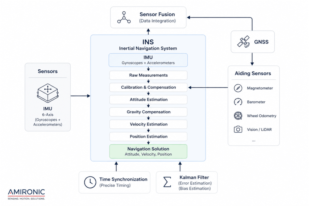
Figure 1 – An IMU provides raw inertial measurements, whereas an INS transforms those measurements into a complete navigation solution through calibration, state estimation, sensor fusion and navigation algorithms.

The First Step – Estimating Platform Attitude

When an IMU begins transmitting data, it has no knowledge of where the platform is or even which direction it is facing.

At every instant, the three gyroscopes measure the angular rate about the sensor’s three axes (X, Y and Z). In other words, they measure how fast the platform is rotating—not its actual orientation.

For example, if a gyroscope measures an angular rate of 20°/s for one second, the platform has rotated approximately 20 degrees. If the same angular rate continues for two seconds, the accumulated rotation becomes approximately 40 degrees.

At first glance, the solution appears straightforward: integrate the angular rate over time to obtain the platform’s orientation.

In reality, this is only the beginning.

Every gyroscope contains small measurement errors, including bias, noise, temperature-dependent drift and calibration errors. When angular rate is continuously integrated, even tiny errors accumulate over time, gradually producing an increasing attitude error.

In other words, even when the platform is perfectly stationary, the navigation system may slowly estimate that it is rotating.

This is one of the fundamental reasons why an INS cannot rely on simple integration of IMU data alone.


Why Is Attitude So Important?

Many engineers associate attitude primarily with stabilization or flight control.

In reality, it forms the foundation of almost every subsequent calculation performed by an inertial navigation system.

An accelerometer cannot distinguish between linear acceleration and the acceleration caused by gravity. Before the INS can calculate the platform’s true linear acceleration, it must first determine the exact orientation of the IMU relative to the Earth.

Only after estimating the platform’s attitude can the navigation system:

  • Transform measurements from the sensor reference frame to the Earth reference frame
  • Remove the gravity component from the accelerometer measurements
  • Calculate true linear acceleration
  • Compute velocity and position

Ultimately, every error in the estimated attitude propagates through the entire navigation chain, affecting all subsequent calculations.

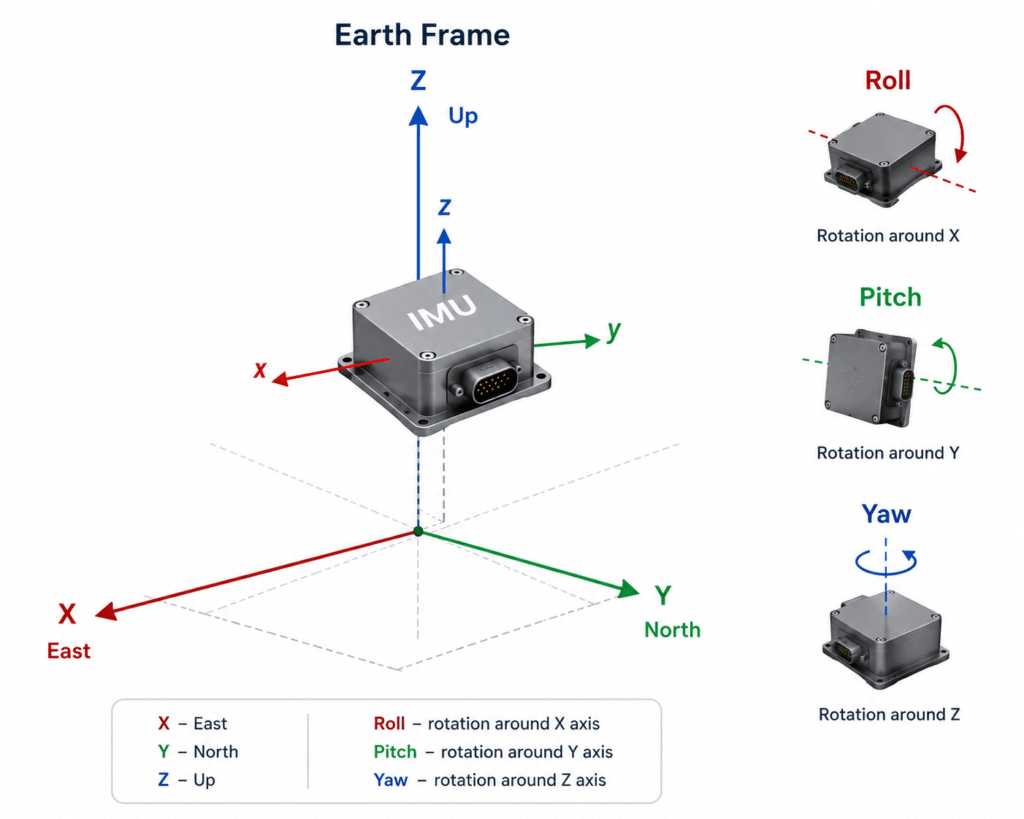
Figure 2 – The INS continuously estimates the platform’s Roll, Pitch and Yaw relative to the Earth reference frame. This attitude estimate forms the foundation for gravity compensation and for all subsequent velocity and position calculations.

The Second Step – Why Doesn’t an Accelerometer Measure Only Acceleration?

This is one of the most misunderstood concepts in inertial navigation.

Many people assume that an accelerometer simply measures the platform’s linear acceleration. In reality, it measures specific force, which includes the effects of gravity.

For example, when a platform is resting motionless on a table, its linear acceleration is zero. Yet one of the accelerometer axes still measures approximately 1g.

In other words, the sensor cannot determine whether the measured force is caused by actual motion or by gravity.

This is precisely why attitude estimation is a fundamental step in every inertial navigation system.

Only after the INS knows the exact orientation of the IMU relative to the Earth can it separate the gravity vector from the measured specific force and calculate the platform’s true linear acceleration.

Without this step, every subsequent velocity and position calculation would be incorrect from the very beginning.


Why Does a Small Attitude Error Become a Large Position Error?

This is one of the most important error mechanisms in inertial navigation.

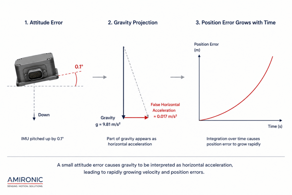
Assume the navigation system makes an attitude estimation error of only 0.1° in pitch.

From the algorithm’s perspective, a small component of the Earth’s gravity vector is mistakenly interpreted as horizontal acceleration.

The navigation system has no way of recognizing that this acceleration is false.

Instead, it assumes the platform is genuinely accelerating.

From that moment, the error begins to propagate:

  • The false acceleration is integrated, producing a velocity error.
  • The velocity error is integrated again, producing a position error.
  • As time passes, the accumulated navigation error continues to grow.

This is one of the fundamental reasons why an INS cannot rely solely on inertial measurements for extended periods. To limit long-term drift, modern navigation systems periodically update the inertial solution using external aiding sources such as GNSS, Visual Odometry, LiDAR, Radar, or other navigation sensors.

Figure 3 – A small attitude estimation error causes part of the gravity vector to be interpreted as horizontal acceleration. After continuous integration, this false acceleration produces an increasing velocity error, which ultimately grows into a significant position error.

The Third Step – From Acceleration to Velocity

Once the INS has estimated the platform’s attitude and removed the effect of gravity from the accelerometer measurements, the remaining acceleration can finally be used for navigation.

At this stage, the measured acceleration no longer represents the total force acting on the sensor. Instead, it represents the platform’s true linear acceleration in the Earth reference frame.

The next calculation is mathematically simple—but fundamentally important.

The INS integrates linear acceleration over time to estimate the platform’s velocity.

If the platform accelerates at a constant rate for several seconds, its velocity increases accordingly.

In practice, this calculation is performed thousands of times per second, with every new IMU measurement updating the estimated velocity.

As a result, the quality of the velocity estimate depends directly on the quality of the IMU measurements, the sampling rate, timing accuracy and, above all, the accuracy of the estimated attitude.


Why Does Velocity Error Continue to Grow?

One of the defining characteristics of inertial navigation systems is that they rely on continuous integration.

Unlike a sensor that reports an instantaneous measurement, an INS accumulates information over time.

If a small acceleration error is introduced—even one caused by an attitude error of only 0.1°—that error does not disappear in the next measurement.

Instead, the INS continues to integrate the false acceleration, causing the estimated velocity to drift further from the true value.

In other words, even if the false acceleration remains constant, the velocity error continues to grow.

This is why high-performance INS solutions place such a strong emphasis on minimizing sensor bias, compensating for temperature effects and periodically correcting the inertial solution using external aiding sources.


The Fourth Step – From Velocity to Position

Once velocity has been estimated, the navigation system performs another integration to determine the platform’s position.

Conceptually, the process is straightforward:

  • Acceleration → Velocity
  • Velocity → Position

However, this is also where the greatest challenge of inertial navigation becomes apparent.

If acceleration errors accumulate into velocity errors, those velocity errors are integrated once again, producing even larger position errors.

As a result, even an INS built around a high-performance IMU cannot maintain perfect accuracy indefinitely without external navigation updates.

The length of time an INS can operate autonomously depends on many factors, including IMU performance, calibration quality, navigation algorithms, platform dynamics and operating conditions.


Why Does an INS Need Navigation Updates?

So far, we have described what appears to be a simple processing chain:

  1. Estimate attitude.
  2. Compute true linear acceleration.
  3. Integrate acceleration to obtain velocity.
  4. Integrate velocity to obtain position.

In reality, each stage depends entirely on the accuracy of the previous one.

A small error introduced at the beginning of the process propagates through every subsequent calculation, becoming larger after each integration step.

This is why modern navigation systems do not rely on inertial measurements alone.

At some point, an external aiding source is required to correct the accumulated drift and maintain long-term navigation accuracy.

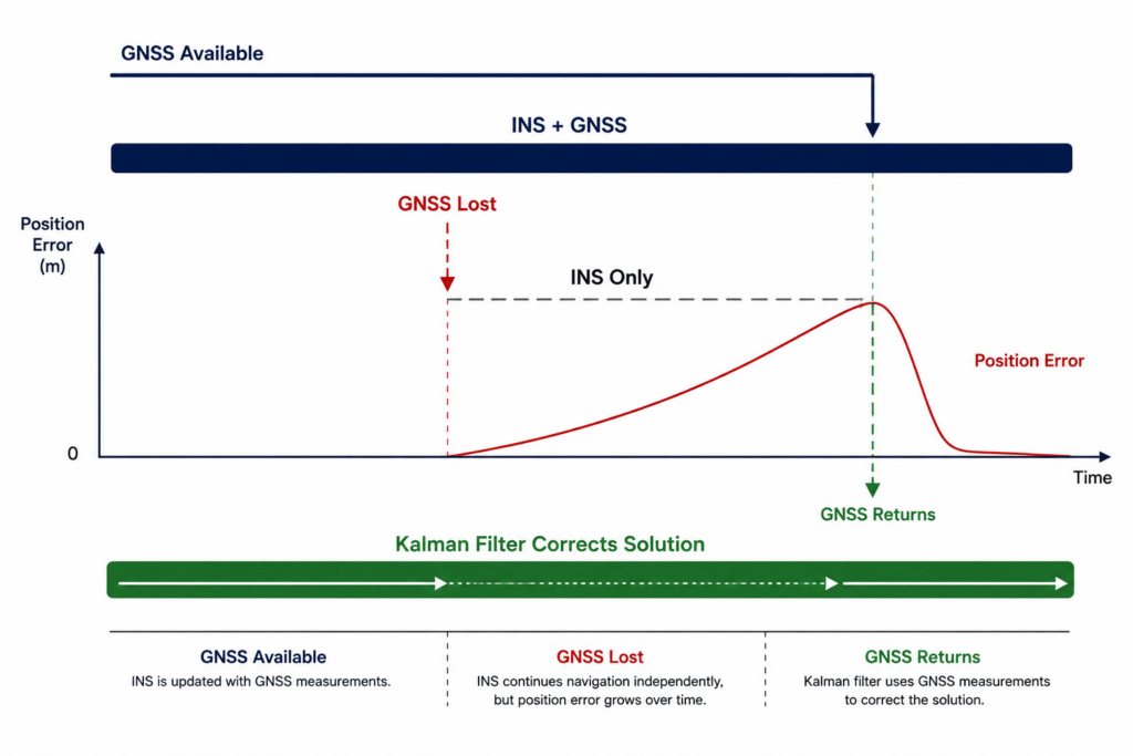
Figure 4 – During a GNSS outage, the INS continues to provide a continuous navigation solution using inertial measurements alone. Once external aiding data becomes available again, the sensor fusion algorithm updates the navigation state estimate and reduces the accumulated error.

The Fifth Step – Why a High-Performance IMU Is Still Not Enough

Up to this point, we have described inertial navigation as if it were a simple, linear process:

  • Measure angular rate
  • Estimate attitude
  • Remove gravity
  • Compute velocity
  • Estimate position

Real-world tactical navigation systems are far more complex.

Every stage of the navigation process is influenced by multiple error sources acting simultaneously.

Some originate within the sensors themselves, while others are introduced by platform dynamics, IMU installation, temperature variations, vibration, timing accuracy and the mathematical models used by the navigation system.

For this reason, developing a high-performance INS involves much more than selecting an IMU with excellent specifications.

It requires careful calibration, system characterization, sensor integration and continuous error estimation.


Major Error Sources in an Inertial Navigation System

In an operational navigation system, numerous error mechanisms influence the quality of the navigation solution.

Typical examples include:

  • Gyroscope bias
  • Accelerometer bias
  • Sensor noise
  • Scale factor error
  • Sensor-to-platform misalignment
  • Temperature drift
  • Mechanical vibration
  • Timing and synchronization errors
  • Lever arm errors
  • Boresight misalignment between the IMU and other sensors

Individually, each of these errors may appear insignificant.

Over time, however, their combined effect can become substantial.

This is why modern INS solutions are designed not only to measure motion, but also to continuously estimate, model and compensate for navigation errors.


Table 1 – Common Error Sources in an INS

Error Source Typical Effect
Gyroscope Bias Gradually increasing attitude error
Accelerometer Bias Accumulating velocity and position error
Misalignment Incorrect transformation of measured acceleration
Temperature Drift Gradual changes in sensor performance
Mechanical Vibration Increased measurement noise and dynamic errors
Timing Error Reduced Sensor Fusion accuracy and synchronization errors

The Sixth Step – The Role of the Kalman Filter

Few concepts in inertial navigation are as well known—or as frequently misunderstood—as the Kalman Filter.

It is often described as a “magic algorithm” that corrects every navigation error.

In reality, its role is far more sophisticated.

The Kalman Filter does not replace the navigation system, nor does it independently compute position.

Instead, it continuously estimates the system state, tracks accumulated errors and optimally combines all available sources of information.

In other words, it helps the INS determine how much confidence should be assigned to each measurement at every instant.

When a new GNSS measurement becomes available, the Kalman Filter does not simply overwrite the inertial solution.

Instead, it compares the predicted navigation state generated by the INS with the measured navigation state provided by GNSS, estimates the difference between them and updates the complete system state accordingly.

This continuous estimation process allows modern navigation systems to maintain stable and reliable performance, even when one of the available sensors temporarily becomes degraded or unavailable.


So, How Is a Tactical Navigation System Actually Built?

Once the operating principles of inertial navigation are understood, it becomes clear why designing a tactical navigation system does not begin with selecting an IMU.

It begins with defining the system requirements.

Questions such as:

  • Is the platform a UAV or a ground vehicle?
  • How long must it operate without GNSS updates?
  • Is the primary objective stabilization, navigation, guidance or flight control?

These requirements influence every engineering decision that follows.

In many projects, the quality of the overall system integration has a greater impact on navigation performance than the IMU alone.

A typical tactical navigation architecture combines several layers working simultaneously:

  • An IMU providing high-rate inertial measurements
  • An INS performing navigation computations
  • Calibration and error compensation routines
  • Sensor Fusion algorithms
  • A Kalman Filter for continuous state estimation
  • External aiding sources such as GNSS, cameras, LiDAR, radar, wheel odometry or other application-specific sensors

Together, these components provide a continuous navigation solution—even when one of the aiding sensors temporarily becomes unavailable.


Selecting an IMU Is Only the Beginning

One characteristic shared by successful navigation projects is that the engineering discussion never ends with the choice of sensor.

System engineers typically ask different questions:

  • Is the sampling rate appropriate for the platform dynamics?
  • What is the end-to-end latency?
  • How is precise time synchronization achieved?
  • Does the IMU support external synchronization?
  • How stable is the sensor bias over temperature?
  • How will the IMU be integrated with the remaining navigation sensors?
  • How will system alignment be performed after installation?

These are the questions that separate a navigation system that performs well in the laboratory from one that continues to perform reliably under real operational conditions.


Table 2 – Typical Building Blocks of a Tactical Navigation System

Component Primary Function
IMU Measures angular rate and specific force
INS Estimates attitude, velocity and position
Time Synchronization Aligns measurements from all sensors in time
Calibration Compensates sensor imperfections and systematic errors
Sensor Fusion Combines information from multiple sensors
Kalman Filter Estimates system state and accumulated errors
GNSS & Aiding Sensors Correct long-term navigation drift

Conclusion

The IMU Is Only the Beginning

At first glance, inertial navigation appears to be little more than integrating gyroscope and accelerometer measurements.

In reality, it is one of the most sophisticated real-time estimation problems in modern control and navigation engineering.

Transforming raw IMU measurements into a stable navigation solution requires far more than high-quality sensors. It depends on calibration, mathematical models, state estimation, precise timing, sensor fusion and continuous error management.

For this reason, the performance of a tactical navigation system is determined not only by the quality of its IMU, but also by the intelligence of the algorithms built around it.


A Final Thought

Two engineering teams can build navigation systems around exactly the same IMU and achieve dramatically different performance. In most cases, the difference is not the sensor itself—it is the quality of the integration, time synchronization, calibration, sensor fusion and error modeling throughout the navigation chain.

Case Study – What Happens When a UAV Loses GNSS for 30 Seconds?

The following scenario illustrates how an inertial navigation system behaves during a temporary GNSS outage. Actual performance depends on many factors, including IMU quality, navigation algorithms, calibration, platform dynamics and operating conditions.

T = 0 Seconds

The UAV is in normal flight.

The navigation system is operating in a tightly coupled INS/GNSS configuration.

During every processing cycle, the navigation computer combines:

  • IMU measurements
  • GNSS observations
  • The platform’s dynamic model

The Kalman Filter continuously updates the system’s state estimate, including position, velocity, attitude and the estimated sensor errors.


T = 3 Seconds

The GNSS signal is lost.

The UAV does not lose navigation.

The INS continues to estimate:

  • Attitude
  • Velocity
  • Position

using IMU measurements alone.

From the operator’s perspective, there is typically no immediate indication that GNSS has been lost.


T = 10 Seconds

The navigation solution remains stable.

However, without new GNSS updates, the INS can no longer correct the accumulated inertial errors.

The navigation solution remains continuous, but the uncertainty associated with the estimated position gradually increases.


T = 20 Seconds

Small gyroscope bias, accelerometer bias, measurement noise and attitude estimation errors begin to accumulate.

At this stage, navigation performance depends largely on:

  • IMU performance
  • Calibration quality
  • INS algorithm design
  • Sensor Fusion performance prior to the GNSS outage

T = 30 Seconds

The INS continues to provide a valid navigation solution.

However, without external navigation updates, the accumulated error continues to grow.

The drift rate depends on many factors, including:

  • Gyroscope performance
  • Bias Stability
  • Angle Random Walk (ARW)
  • Bias Over Temperature
  • Navigation algorithms
  • Platform dynamics

For this reason, there is no single drift specification that applies to every inertial navigation system.


T = 31 Seconds

GNSS becomes available again.

The Kalman Filter compares:

Prediction
The navigation solution propagated by the INS during the outage.

with

Measurement
The newly received GNSS position.

Using the Sensor Fusion process, the filter updates the complete navigation state, reduces the accumulated error and restores the navigation solution.

Mission Log

MISSION TIME 00:00
GNSS Locked ✓

MISSION TIME 00:08
GNSS Signal Lost

MISSION TIME 00:15
INS Navigation Active

MISSION TIME 00:25
Position Error Growing

MISSION TIME 00:31
GNSS Reacquired

MISSION TIME 00:32
Navigation Solution Updated

What Can We Learn from This Scenario?

During a GNSS-denied period, the navigation system relies almost entirely on the quality of its inertial measurements.

As a result, characteristics such as:

  • Bias Stability
  • Bias Over Temperature
  • Angle Random Walk (ARW)
  • Data Rate
  • Message Latency
  • External Synchronization

can have a significant impact on navigation performance until an external aiding source becomes available again.

IMUs such as the LandMark™ 006 from Gladiator Technologies are designed for applications requiring high output rates (up to 10 kHz), bandwidths of up to 600 Hz, ultra-low message latency (below 20 µs in the VELOX Plus version), external synchronization and full temperature calibration.

These capabilities provide high-quality inertial measurements for advanced stabilization, guidance and navigation systems, while the overall system performance ultimately depends on the INS architecture, Sensor Fusion algorithms and navigation software built around the IMU.

Frequently Asked Questions (FAQ)

Why Do We Need an INS If We Already Have GNSS?

GNSS provides highly accurate positioning, but it can be affected by signal blockage, jamming, spoofing or environmental conditions. In addition, its update rate is typically much lower than the sampling rate of an IMU.

An Inertial Navigation System (INS) continues to provide a continuous navigation solution even when GNSS signals are unavailable, making it a fundamental component of modern navigation, stabilization and tactical control systems.


Can an IMU Calculate Position?

No.

An IMU measures only angular rate and specific force.

To estimate position, velocity and attitude, an INS is required to integrate the inertial measurements while applying calibration, error compensation and external aiding information.


Can an INS Operate Without GNSS?

Yes.

An INS can continue estimating attitude, velocity and position even when GNSS is unavailable.

However, without external navigation updates, inertial errors gradually accumulate over time. The resulting navigation drift depends on IMU performance, calibration quality, navigation algorithms and platform dynamics.


Is the Kalman Filter a Navigation System?

No.

The Kalman Filter is a state estimation algorithm.

Its role is to optimally combine IMU measurements with external aiding sources, such as GNSS, while continuously estimating and compensating for accumulated navigation errors.


What Is Sensor Fusion?

Sensor Fusion is the process of combining information from multiple sensors to produce a more accurate and reliable navigation solution.

A modern navigation system may combine data from:

  • IMU
  • GNSS
  • Vision cameras
  • LiDAR
  • Radar
  • Wheel odometry
  • Barometric sensors

Each sensor has different strengths and limitations. Sensor Fusion algorithms determine how much confidence should be assigned to each measurement at any given time.


Is a High-Performance IMU Enough to Build a Tactical Navigation System?

A high-performance IMU is essential—but it is not sufficient by itself.

Overall navigation performance also depends on the quality of the navigation algorithms, calibration procedures, time synchronization, system integration, external aiding sources and the ability to model and compensate navigation errors.


Which IMU Specifications Matter Most for Navigation Applications?

Beyond measurement range, system engineers typically evaluate:

  • Bias Stability
  • Bias Over Temperature
  • Angle Random Walk (ARW)
  • Output Data Rate
  • Message Latency
  • External Synchronization
  • Bandwidth
  • Alignment Accuracy

Together, these parameters have a significant impact on the quality of the inertial measurements and, ultimately, on the performance of the INS.


Glossary

IMU (Inertial Measurement Unit)

An electronic device that typically contains three gyroscopes and three accelerometers for measuring angular rate and specific force.


INS (Inertial Navigation System)

A navigation system that processes IMU measurements to estimate the platform’s attitude, velocity and position.


GNSS (Global Navigation Satellite System)

A collective term for satellite navigation systems such as GPS, Galileo, GLONASS and BeiDou.


Gyroscope

A sensor that measures angular rate about one or more axes.


Accelerometer

A sensor that measures specific force, including the effects of gravity.


Attitude

The orientation of a platform relative to the Earth’s reference frame.

Attitude is commonly expressed as Roll, Pitch and Yaw, or mathematically using quaternions.


Roll / Pitch / Yaw

The three rotational degrees of freedom of a platform:

  • Roll – Rotation about the longitudinal axis
  • Pitch – Rotation about the lateral axis
  • Yaw – Rotation about the vertical axis

Sensor Fusion

The process of combining measurements from multiple sensors to produce a more accurate, robust and reliable navigation solution.


Kalman Filter

A state estimation algorithm that combines mathematical system models with sensor measurements while accounting for the uncertainty associated with each information source.


Bias

A constant or slowly varying sensor offset.

Even a small bias can accumulate over time and produce significant navigation errors after repeated integration.


Bias Stability

A measure of how stable the sensor bias remains over time.

Better bias stability generally results in lower navigation drift.


Angle Random Walk (ARW)

A measure of the gyroscope’s random noise.

Lower ARW values generally improve long-term attitude estimation accuracy.


Dead Reckoning

A navigation technique that estimates the current position by integrating previous motion measurements without relying on external positioning sources.


Drift

The gradual accumulation of navigation error over time due to repeated integration of small sensor errors.


Alignment

The process of determining the orientation of the IMU relative to the vehicle and the navigation reference frame before navigation begins.


Time Synchronization

The precise synchronization of measurements from all sensors within the navigation system.

Even millisecond-level timing errors can significantly degrade Sensor Fusion performance in highly dynamic applications.


External Synchronization

The ability to synchronize IMU measurements to an external timing reference, ensuring precise alignment with other sensors or mission systems.


Navigation Solution

The estimated state of the platform at any given moment, typically including position, velocity, attitude and, in many systems, an estimate of the uncertainty associated with those values.

Tags: Gladiator_Technologies

Related Articles

Mission-Grade Stabilization in Dynamic EO/IR Systems: Why Bandwidth, Data Rate, and Phase Lag Define Gimbal Performance

01/03/2026amironicLTD

Why a Smaller IMU Can Save Months of Development

30/06/2026amironicLTD

Scale Factor in MEMS IMUs – The Error That Quietly Destroys Accuracy

11/05/2026amironicLTD

Recent Posts

  • From IMU to INS: How a Tactical Navigation System Is Really Built
  • What Can We Learn from 40-Year-Old Hydraulic-Magnetic Circuit Breakers Still in Service?
  • Why Did Your Footswitch Fail After Just Six Months – Even Though It Was Rated for One Million Operations?
  • Your System Has Powered Up – But Does It Know Where It Is? Absolute Position Sensors vs. Homing
  • When the System Starts to Vibrate – Don’t Rush to Retune the Motion Controller

Categories

  • Air Switch
  • Circuit Breakers
  • Elapsed Time Indicator
  • Feedthrough
  • Footswitches
  • Gears & Transmission
  • Hour Meters
  • Infra Red Switches
  • INFRARED LAMPS
  • Low Noise Inertial MEMS
  • Mechanics
  • MEMS Gyroscope
  • MEMS Inertial
  • Microelectronics
  • Motors
  • Position Sensors
  • Power Supply
  • Pressure Sensors
  • Pressure Switch
  • Temperature Sensors
  • Tungsten and Molybdenum
  • Uncategorized
  • Vacuum Switches

Quick Contact

Fill out the form and our representatives will return to you

    Name (required)

    Email (required)

    Phone

    Message

    This site is protected by reCAPTCHA and the Google
    Privacy Policy and
    Terms of Service apply.

    Amironic Ltd.

    3 Rabinovich Street, Petah Tikva 4928144 , Israel. Tel: +972-3-9047744 E-mail: office@amironic.co.il
    Email
    Facebook
    Twitter
    LinkedIn
    YouTube
    Press on the ISO Certificate below for download
    ISO 9001:2015 Certification
    • MEMS Inertial
    • Circuit Breakers
    • Footswitches
    • Mechanical & Transmisions
    • Sensors
    • Motors
    • Electronics
    • Hand Control
    • Power Solutions

    News

    • From IMU to INS: How a Tactical Navigation System Is Really Built
    • What Can We Learn from 40-Year-Old Hydraulic-Magnetic Circuit Breakers Still in Service?
    • Why Did Your Footswitch Fail After Just Six Months – Even Though It Was Rated for One Million Operations?
    • Your System Has Powered Up – But Does It Know Where It Is? Absolute Position Sensors vs. Homing
    • When the System Starts to Vibrate – Don’t Rush to Retune the Motion Controller
    About AmironicContactעברית
    © 2022 Amironic All rights reserved. All Trademarks are the property of their respective owners.
    • Increase Font
    • Decrease Font
    • Black & White
    • Inverse Colors
    • Highlight Links
    • Regular Font
    • Reset