flagעברית
flagEnglish
3 Rabinovich St., Petah-Tikva, Israel
+972 3 9047744
office@amironic.co.il
Facebook
Twitter
LinkedIn
YouTube
  • Products
    • MEMS Inertial
      • Gyros & Accels
      • IMU
      • Inertial Navigation
      • AHRS
    • Circuit Breakers
      • Airpax Circuit Breakers
      • Electronic Circuit Breakers
      • Aircraft Circuit Breakers
      • Thermal Circuit Breakers
      • Sealing Solutions & Guards
    • Footswitches
      • Pedals & Bellows
      • USB
      • Air Switches
      • Medical
      • Modular Bases System
      • Industrial
      • Foot Potentiometers
      • Wireless
    • Mechanical & Transmisions
      • Gears
      • Sealing Solutions
      • Gearboxes
      • Couplings
      • Shafts & Bearings
      • Fasteners
      • Mechanical & Springs
      • Linear Motion
      • Anti-Vibration
    • Sensors
      • Thermostats
      • Temperature
      • Position
      • Pressure
      • Speed
      • Level Sensor
      • Load Cells
      • Flex Sensors
      • Membrane Potentiometer
    • Motors
      • Geared DC
      • Brushless DC
      • Step Motors with Gearbox
      • Torque Motors & Brushless Servo
      • DC Motors
    • Electronics
      • Xenon & IR Lamps
      • Counters & Meters
      • Microelectronics Packaging
      • Waterproof Switches
      • Micro Switches
    • Hand Control
      • Operator Controls (JOYSTICK)
      • Electrical
      • Pneumatic (Medical)
      • USB Hand Control
      • Air Push Button
      • Pressure Switch
      • IR Switch
    • Power Solutions
      • Rugged & Military Power Supply
      • Input Power Protection
      • Sealed Military Power Adaptor
      • Triple Output Military Power Supply Series – up to 250 W
    • Materials
      • Molybdenum and Advanced Alloys (TZM, MOLA, HCT)
      • Tungsten (Wolfram) and Advanced Alloys – High-Performance Materials for Extreme Conditions
      • Materials for Gears
  • Shop
  • Companies
  • About Amironic
  • News
  • Contact
Product was added to your cart

Cart

waze

Why Every Battery Pack Needs a Temperature Sensor – Not Just Electric Vehicles

Temperature Sensors09/08/2026amironicLTD

When discussing temperature monitoring in lithium batteries, the first application that usually comes to mind is the electric vehicle.

But Battery Packs are now found almost everywhere: UAVs and unmanned platforms, robots and AGVs, mobile defense systems, Energy Storage Systems (ESS), communications equipment, backup power systems, medical equipment and industrial machinery.

And all of these applications share the same fundamental engineering challenge:

A battery is not only a source of energy. It is also a source of heat.

During charging and discharging, internal losses generate heat within the cells. The higher the current, the more demanding the charge or discharge profile, and the harsher the environmental conditions, the more important temperature monitoring becomes as part of the Battery Management System.

A BMS can monitor the voltage of each cell and measure the current flowing through the Battery Pack. But without thermal information, it is missing a critical piece of data:

What is actually happening to the cells thermally?

A temperature sensor installed directly on the cell or in close thermal contact with it enables the system to detect rising temperatures, compare temperatures between different areas of the Pack, control charging and discharging, activate cooling and, when necessary, limit or stop battery operation.

And this is just as relevant to an electric vehicle battery as it is to the Battery Pack powering a tactical UAV.

Why Is Battery Cell Temperature So Important?

A lithium cell does not behave the same way at every temperature.

Temperature affects internal resistance, current delivery capability, permissible charging rates, battery performance and the rate at which the cell ages.

But there is another parameter that can sometimes be even more important than absolute temperature:

Temperature Uniformity across the Battery Pack.

Consider a system containing dozens of cells.

The “average” battery temperature may appear perfectly normal while one individual cell, or one particular area inside the enclosure, is operating significantly hotter than the others.

From the BMS perspective, therefore, the question is not simply:

“What is the battery temperature?”

It is also:

“Where is the hottest point, and are all the cells behaving in a similar way?”

This is one of the reasons why advanced Battery Packs may incorporate multiple temperature sensors rather than relying on a single measurement point.

In Israel, a Battery Pack Means Much More Than EV

In the Israeli market, the description EV Battery Cell Temperature Sensor may actually lead an engineer to assume that the product is not relevant to their application.

In practice, the same measurement principle applies to a much wider range of systems.

Consider a UAV beginning a mission on a hot Israeli summer day. Its Battery Pack may already be exposed to elevated ambient temperatures before the mission starts, and then immediately experience a high discharge rate during takeoff and climb.

Or consider a UGV carrying power-hungry electronic systems.

Or an ESS installation containing hundreds or thousands of cells operating over many years, where the ability to detect a localized thermal change can be important.

In each of these cases, temperature monitoring is part of understanding the real-time condition of the battery.

And this brings us to an interesting question:

Why Does This Sensor Look Like a Ring?

The ETP-ST-21-35-B57861S0103A039 from Variohm Eurosensor is a particularly interesting example.

At first glance, its geometry looks somewhat unusual.

Instead of a conventional metal Probe, a flat sensor or a small Thermistor bonded to the surface of the cell, we have a hollow cylindrical Sleeve.

This is not an accidental design choice.

The Sleeve is designed to provide a defined geometric fit around a cylindrical battery cell. In effect, the sensor becomes part of the mechanical interface with the cell rather than a small component whose position depends entirely on a single bonding point.

In the version shown in the datasheet, the Sleeve has an internal diameter of approximately 20.5 mm, an external diameter of approximately 22.5 mm and a height of 10 mm. The cable exits from a defined position at the edge of the Sleeve. The product is also available in a range of sizes and can be customized to suit the application.

What Is the Engineering Advantage of the Sleeve?

When a conventional Thermistor is simply bonded to a battery cell, measurement quality can depend on several assembly variables: sensor position, bonding quality, contact pressure, adhesive material and the ability to reproduce the same installation consistently in serial production.

The Sleeve design takes a different approach:

Make the sensor position part of the mechanical geometry of the assembly.

This is particularly interesting in serial Battery Pack production, where mechanical Repeatability can be just as important as the accuracy of the sensing element itself.

It also illustrates one of the strengths of Variohm Eurosensor’s approach to temperature sensing: the solution is not limited to selecting a Thermistor from a catalogue. The sensing element can be integrated into a mechanical format designed around the application, with different sizes, resistance values and customization options available.

In this specific version, the Sleeve is manufactured from Arnitel, and the complete assembly is designed for an operating temperature range of -40°C to +130°C.
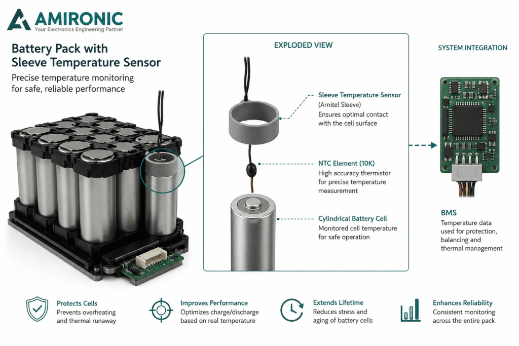
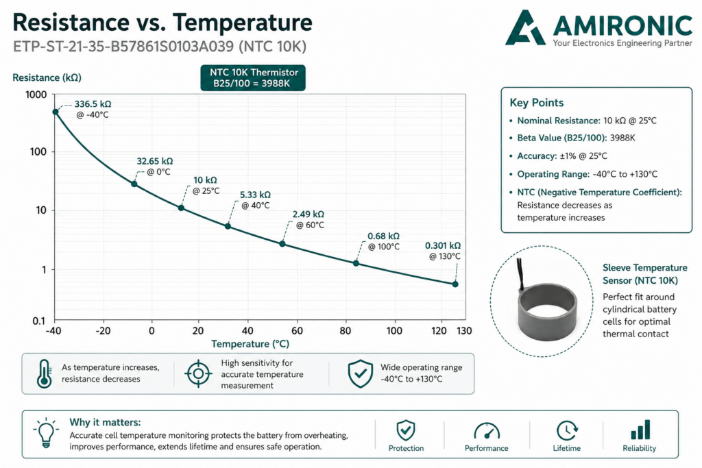
Figure: Battery cell temperature monitoring using an NTC Sleeve Sensor. The ring-shaped design provides consistent positioning and thermal contact with the cylindrical cell, while the temperature data is transmitted to the BMS for battery monitoring and thermal management.

What Is Actually Inside the Sleeve?

Inside the ring-shaped structure is the component that performs the actual temperature measurement – the NTC Thermistor.

The ETP-ST-21-35-B57861S0103A039 uses a TDK Electronics B57861S0103A039 Thermistor, with a nominal resistance of 10 kΩ at 25°C and a Beta value of 3988K. According to the datasheet, both accuracy and tolerance are ±1% at 25°C, while the complete sensor assembly is specified for an operating temperature range of -40°C to +130°C.

In other words, the Sleeve provides the mechanical interface that positions the sensor relative to the battery cell, while the NTC is the sensing element that converts changes in temperature into changes in electrical resistance that can be measured by the BMS.

How Does an NTC Measure the Temperature of the Cell?

NTC stands for Negative Temperature Coefficient.

The principle is straightforward: as temperature increases, the electrical resistance of the sensor decreases.

For this particular sensor:

  • At 0°C, resistance is approximately 32.65 kΩ
  • At 25°C, resistance is 10 kΩ
  • At 40°C, it decreases to approximately 5.327 kΩ
  • At 60°C, it decreases to approximately 2.488 kΩ
  • At 100°C, it is approximately 0.680 kΩ
  • At 130°C, it falls to approximately 0.301 kΩ

These values also illustrate an important characteristic: the relationship between temperature and resistance is non-linear.

The BMS measures the resistance, or more commonly the voltage in a measurement circuit incorporating the Thermistor, and converts that electrical value into temperature according to the sensor’s Resistance vs. Temperature characteristic.

Why Use an NTC 10K?

An NTC 10K is widely used for temperature measurement in electronic systems and Battery Packs because it is compact, sensitive to temperature changes, relatively straightforward to integrate into the measurement circuit and does not require a complex sensing architecture.

However, it is important to understand that “10K” does not mean that the sensor always has a resistance of 10 kΩ.

It means that its nominal resistance is 10 kΩ at the reference temperature of 25°C.

As the temperature changes, the resistance changes significantly.

And that is exactly what the BMS uses to determine the temperature of the battery cell.

Resistance vs. Temperature – Why Is the Curve Important?

When the manufacturer’s data is plotted on a graph, the characteristic becomes immediately clear: resistance is high at low temperatures and decreases rapidly as temperature rises.

For example, increasing the temperature from 25°C to 60°C changes the resistance from 10 kΩ to only about 2.49 kΩ. At 100°C, it has dropped to approximately 680Ω.

This is more than just an interesting characteristic of the Thermistor. It is effectively the thermal language between the battery cell and the control system.

The BMS does not directly “see” temperature. It sees an electrical signal. The Resistance vs. Temperature curve is what allows that signal to be translated into the actual temperature of the cell.

Figure: Resistance vs. Temperature curve for the ETP-ST-21-35-B57861S0103A039 NTC 10K sensor. As the battery cell temperature increases, the sensor resistance decreases non-linearly, allowing the BMS to calculate the cell temperature in real time.

What Does the BMS Do with the Temperature Data?

Temperature measurement by itself is not the goal. The real value comes when the sensor data is fed into the BMS and used to influence how the battery is managed.

Depending on the system design, temperature data can be used by the controller to limit charging or discharging current, activate a cooling system, generate an alert or, under abnormal conditions, stop operation to protect the battery.

For example, if the BMS detects that one particular cell is heating up faster than the surrounding cells, this information may indicate a localized issue even before the average temperature of the Battery Pack appears abnormal.

Therefore, in larger systems, the question is not only whether the battery is too hot, but also:

Are there abnormal temperature differences between different areas of the Battery Pack?

Why Is One Temperature Sensor Not Always Enough?

A Battery Pack is not a thermally uniform structure.

Cells located in the center of an enclosure may cool differently from those near the edges. Power electronics, Busbars, the cooling system, enclosure design and airflow can all create localized temperature differences.

Therefore, installing a single sensor in a “convenient” location does not guarantee that it is measuring the point that really matters.

In some systems, it makes more sense to use multiple measurement points and create a basic Thermal Map of the Battery Pack.

This makes it possible to compare different areas and identify Hot Spots rather than relying on a single measurement that could conceal a developing localized thermal issue.

And This Brings Us Back to the Sensor’s Unusual Geometry

This is where the Sleeve design of the ETP-ST-21-35-B57861S0103A039 offers an interesting advantage.

According to the drawing, this version has an internal diameter of approximately 20.5 mm, an external diameter of approximately 22.5 mm and a height of 10 mm. The cable length is approximately 341 mm.

Instead of deciding where to bond a small Thermistor to each individual cell, the ring-shaped design provides a defined mechanical solution that fits around the cell.

This becomes particularly important in serial production.

If the sensor is installed in one position in the first Battery Pack and shifts by several millimeters in the next, the thermal contact conditions may not necessarily be identical. When the sensing element is integrated into a mechanical component designed to fit around the cell, it becomes easier to achieve Repeatability from one assembly to the next.

In other words, the unusual geometry is not a disadvantage.

It is part of the engineering solution.

Case Study: ETP-ST-21-35-B57861S0103A039 in a Battery Pack

Consider a hypothetical Israeli system based on a Battery Pack with cylindrical cells, designed to power a mobile robot or unmanned platform.

Important: This is an engineering case study for illustration purposes and not a documented customer application from the datasheet.

The system is required to operate during the Israeli summer, when ambient temperature may already be high before operation even begins. During acceleration, climbing or operation of a high-power Payload, the battery may be required to deliver significant current.

The challenge is not simply to determine whether the Battery Pack is getting hot.

We want to know what is happening to the cells themselves.

For this example, several Variohm Eurosensor ETP-ST-21-35-B57861S0103A039 sensors are installed at predefined locations within the Pack: one near the center, one near the edge and another close to an area expected to experience a higher thermal load.

The sensor incorporates a TDK B57861S0103A039 NTC 10K Thermistor, with a Beta 25/100 value of 3988K, ±1% accuracy at 25°C and an operating temperature range of -40°C to +130°C for the complete sensor assembly.

Suppose a load test produces the following readings:

Sensor A: 42°C
Sensor B: 44°C
Sensor C: 58°C

The important information here is not necessarily the 58°C reading by itself.

The more interesting engineering observation is the ΔT of approximately 14°C between Sensor C and another area of the Pack.

That difference gives the engineer something specific to investigate. Is airflow restricted around Sensor C? Is it located close to a power component? Does the enclosure geometry create local heat accumulation? Is there an issue with the thermal interface?

After a mechanical modification or improvement to the cooling system, the same test can be repeated to determine whether the temperature distribution has improved.

In this sense, temperature sensors are not used only for battery protection.

They also become an engineering tool for developing, testing and validating the thermal design of the Battery Pack.

Not Just Overtemperature – Low Temperature Matters Too

It is easy to assume that a battery temperature sensor exists only to detect overheating.

But the required measurement range can be much wider.

The sensor in our example is specified for an assembly operating range of -40°C to +130°C. At -40°C, the NTC resistance reaches approximately 336.5 kΩ, compared with 10 kΩ at 25°C and only about 0.301 kΩ at 130°C.

For export-oriented equipment, defense systems, UAVs and other mobile platforms, the ability to monitor temperature across such a wide range gives the control system valuable thermal information even under demanding environmental conditions.

Figure: Temperature mapping across multiple points within a Battery Pack. Using multiple sensors makes it possible to identify localized Hot Spots and temperature differences between cells, even when the overall battery temperature still appears to be within the normal range.

How Do We Determine Where to Position the Temperature Sensors?

Selecting an accurate sensor is only part of the design process. If the sensor is installed in the wrong location, even an excellent sensor may provide only a partial picture of the thermal conditions inside the Battery Pack.

Sensor placement should be determined according to the thermal architecture of the system: which cells are expected to operate under higher loads, where airflow is restricted, where power components are located, how the cooling system is designed, and which areas are most likely to accumulate heat.

For this reason, temperature sensors should ideally be considered as part of the Battery Pack design from the development stage, rather than as components added at the end of the project.

In a new system, engineers may begin development testing with a relatively large number of measurement points. Once the thermal behavior of the Pack is understood, the most critical locations can be identified for monitoring in the production design.

Why Can Direct Cell Temperature Measurement Be Important?

The air temperature inside a battery enclosure is not necessarily the same as the temperature of the battery cell.

Similarly, a temperature sensor mounted on the BMS PCB does not necessarily tell us what is happening at the hottest point within the battery.

When the objective is to understand the thermal behavior of the cell itself, there is an advantage to placing the temperature sensor in close thermal contact with the cell body.

This is where the Sleeve design becomes particularly relevant.

Rather than measuring the environment around the cell, the sensor is designed to fit around a cylindrical cell. In the ETP-ST-21-35-B57861S0103A039, the Sleeve has an internal diameter of approximately 20.5 mm, an external diameter of approximately 22.5 mm and a height of 10 mm.

Naturally, the mechanical and thermal interface must still be evaluated as part of the specific system design. Using a Sleeve does not eliminate the need to consider sensor position, thermal contact, response time and actual installation conditions.

What About the Cable?

In a real Battery Pack, the cable is also part of the engineering design.

A sensor may be installed deep inside a densely packed enclosure while the BMS is located elsewhere. The temperature signal therefore needs to be routed from the cell to the electronics without making the assembly unnecessarily complicated.

The datasheet specifies a multi-strand cable, and the drawing for this particular version shows an overall cable length of approximately 341 ±5 mm. Variohm Eurosensor also offers custom design options and a variety of sizes, meaning that the geometry shown here should not be considered the only possible configuration for every Battery Pack.

This is an important point, particularly for Israeli OEMs.

Sometimes the real engineering requirement is not simply:

“I need a 10K NTC.”

It is:

“I need a 10K NTC that fits my mechanical design, cable length, connector and assembly method.”

This is precisely where an application-focused sensor manufacturer such as Variohm Eurosensor can add value – by developing the sensor assembly around the requirements of the system rather than forcing the system designer to build around a standard off-the-shelf sensor.

A Military Battery Pack, UAV or Robot Is Not Just a Small EV

The thermal principles may be similar, but the operating environment can be completely different.

An electric vehicle Battery Pack is designed as part of a large platform with a dedicated Thermal Management system. In a UAV, UGV, robot or portable system, however, engineers may face much tighter constraints on weight, volume and power consumption.

In addition, the system may transition very quickly from standby to a high-load condition.

In a UAV, for example, takeoff and climbing can require high battery power over a short period. In a mobile robot, motors and Payload systems can create a highly variable load profile. In a portable defense system, even the ambient temperature at the beginning of the mission may be far removed from laboratory conditions.

For an Israeli engineer, therefore, the question should not be:

“Am I developing an electric vehicle, and therefore do I need an EV Battery Sensor?”

The better question is:

“Do I have a Battery Pack where knowing the actual temperature of the cells matters?”

If the answer is yes, the same sensing principle is relevant.

What About Energy Storage Systems – ESS?

In an ESS application, the emphasis may be somewhat different.

The battery may operate for many years and undergo a large number of charge and discharge cycles. Such a system can contain a very large number of cells and modules, making temperature distribution an important parameter for both design and monitoring.

If one area continuously operates at a different temperature from the rest of the system, the engineer is not interested only in whether an emergency threshold has been exceeded. The engineer also wants to understand whether there is persistent thermal non-uniformity within the system.

Temperature monitoring can therefore become part of the overall strategy for performance management, diagnostics and maintenance of the energy storage system.

This demonstrates why the description EV Battery Cell Temperature Sensor may actually be too narrow for the potential of this type of solution.

Variohm Eurosensor itself identifies applications beyond EVs, including industrial equipment, Power & Utilities, transit, HVAC, calibration and instrumentation.

Not Every Battery Pack Needs the Same Sensor

It is important to avoid a “One Size Fits All” approach.

Selecting a temperature sensor for a Battery Pack should take into account factors such as:

  • Cell type and dimensions
  • Required temperature range
  • Measurement accuracy
  • NTC characteristic and Beta value
  • Number of measurement points
  • Thermal contact with the cell
  • Cable length and connector
  • Space limitations within the Pack
  • Environmental conditions
  • BMS requirements

The ETP-ST-21-35-B57861S0103A039 is a good example of why a battery temperature sensor does not have to be a conventional Probe. In this case, the sensing element and the mechanical interface with the cell are effectively engineered as one sensor assembly.

This particular configuration incorporates a TDK Electronics B57861S0103A039 NTC 10K, with a Beta 25/100 value of 3988K, ±1% accuracy at 25°C and an overall operating temperature range of -40°C to +130°C.

More importantly, the broader Variohm Eurosensor approach allows the sensing solution to be adapted around the application, with different sizes, resistance values and custom design options available. This can be especially valuable when the sensor must become an integral part of the Battery Pack rather than simply another component added to it.

The Bottom Line

A temperature sensor is a relatively small component within the system it serves, but the information it provides can be critical.

It enables the BMS to understand not only how much energy is available and how much current is flowing, but also what is happening to the cells thermally.

And the most important message is that this is not an engineering challenge limited to the electric vehicle industry.

In Israel, the same requirement can appear in the Battery Pack of a UAV, robot, UGV, defense system, Energy Storage System, industrial machine or other mobile platform.

A well-designed Battery Pack does more than deliver energy. It also needs to know when – and where – things are getting hot.

And the unusual geometry of the Variohm Eurosensor Sleeve Temperature Sensor illustrates a broader engineering principle particularly well: sometimes good temperature measurement does not begin with choosing the Thermistor.

It begins by asking:

How do we make sure the sensor measures the right place, consistently, in every unit we manufacture?

🧩 Further Reading – Measurement as a System

This article is part of an engineering series exploring how reliable measurement depends on proper system design rather than on a single sensor component.

Before diving deeper into industrial temperature sensing, you may also find the following articles in the series useful:

  • VARIOHM Group – When Measurement Is a System, Not a Component
  • How to Select Sensors for Harsh Environments: An Engineering Guide for Reliable Measurement in the Real World
  • VARIOHM Position Sensors – Engineering Position as a System, Not Just a Signal
  • Industrial Pressure Sensors – When Pressure Measurement Becomes a System Engineering Challenge
  • Industrial Temperature Sensors – When Temperature Measurement Becomes a System Engineering Challenge
  • Choosing the Right Linear Position Sensor: Why Stroke Length Is Only the Beginning
  • Contactless Rotary Position Sensors – Why More and More Systems Are Moving to Non-Contact Sensing
  • Choosing the Right Temperature Probe Mounting
  • How Differential Pressure (ΔP) Can Reveal Problems Long Before a System Shuts Down
  • Your Temperature Sensor Says 80°C. The Real Hot Spot Could Already Be at 130°C
  • Measuring Pressure Without Temperature Is Only Half the Picture
  • Does Your Thermal Protector Really Solve the Problem? Or Just Give the System Another Chance to Fail?
  • Why a Linear Position Sensor Shouldn’t Be Selected by Stroke Alone
  • Your System Has Powered Up – But Does It Know Where It Is? Absolute Position Sensors vs. Homing
  • Your Pressure Sensor May Be Accurate. Your Measurement May Not Be – Why a ±0.5% Accuracy Specification Doesn’t Guarantee a ±0.5% Measurement
  • Why Programming a Rotary Position Sensor to 360° Is Sometimes the First Design Mistake
  • Why a Dual-Channel Rotary Position Sensor Is Not Just a Backup Sensor
  • Your PT100 Sensor Isn’t Reading the Wrong Temperature – Your Wiring Might Be

Common Mistakes in Battery Pack Temperature Monitoring Design

Measuring air temperature instead of cell temperature
A sensor installed inside the enclosure may measure the air surrounding the battery, but not necessarily the temperature of the cell itself. When the objective is to detect a localized Hot Spot, sensor placement and thermal contact with the cell become particularly important.

Using only one sensor for a large Battery Pack
A Battery Pack is not necessarily thermally uniform. Cells located in the center, near the edges or close to power components may operate at different temperatures.

Looking only at maximum temperature
The temperature difference between different areas, ΔT, can also provide valuable information. An unusual temperature difference relative to neighboring cells may justify investigation even before a critical temperature limit is reached.

Selecting an NTC based only on “10K”
Two Thermistors specified as NTC 10K are not necessarily identical. The Resistance vs. Temperature characteristic, Beta value, tolerance and operating temperature range should also be considered.

Ignoring the mechanical installation
Even a highly accurate Thermistor can produce inconsistent results if it is installed differently from one assembly to another. This is one of the reasons why a Sleeve design can be particularly interesting for serial production.

Frequently Asked Questions (FAQ)

What Is an NTC 10K?

An NTC is a Thermistor whose resistance decreases as temperature increases. The designation 10K indicates a nominal resistance of 10 kΩ at 25°C. In the ETP-ST-21-35-B57861S0103A039, resistance decreases to approximately 5.327 kΩ at 40°C and 2.488 kΩ at 60°C.

Why Is a Temperature Sensor Needed If the BMS Already Measures Voltage and Current?

Voltage and current measurements do not provide a direct measurement of battery cell temperature. Temperature sensors provide the BMS with thermal information that can be used by the control and protection system according to the system design.

Is One Temperature Sensor Enough for a Battery Pack?

Not necessarily. It depends on the size of the Pack, number of cells, mechanical design, load profile and cooling system. In systems where localized Hot Spots may develop, multiple measurement points can provide a more complete picture of the thermal conditions inside the Pack.

Why Is the Sensor Designed as a Sleeve?

The Sleeve allows the sensor to fit around a cylindrical battery cell and provides a defined mechanical position relative to the cell. In the configuration shown in the drawing, the internal diameter is approximately 20.5 mm and the external diameter is approximately 22.5 mm.

What Is the Operating Temperature Range of the ETP-ST-21-35-B57861S0103A039?

According to the datasheet, the complete sensor assembly is specified for an operating temperature range of -40°C to +130°C.

Is the Sensor Suitable Only for Electric Vehicles?

No. Variohm Eurosensor identifies applications beyond EVs, including industrial equipment, HVAC, Power & Utilities, home appliances, transit, calibration and instrumentation.

Can the Sensor Be Customized for the Application?

Yes. The Variohm Eurosensor datasheet specifies a variety of sizes, different resistance values and Custom Design options, allowing the sensor solution to be adapted to the requirements of the application.

Key Terms

Battery Management System (BMS) – An electronic system used to monitor and manage a Battery Pack.

NTC Thermistor – A temperature-dependent resistor whose resistance decreases as temperature increases.

R25 – The resistance of a Thermistor at 25°C. In this case, 10 kΩ.

Beta Value – A parameter describing the Resistance vs. Temperature characteristic of an NTC Thermistor. For the sensor discussed here, B25/100 is 3988K.

Hot Spot – A localized area operating at a higher temperature than surrounding areas of the system.

ΔT – Temperature Difference – The difference in temperature between two measurement points.

Thermal Management – The methods used to manage system temperature, including heat conduction, airflow and cooling.

Sleeve Temperature Sensor – A temperature sensor whose sleeve-shaped mechanical structure allows it to be installed around the object being measured.

Thermal Contact – The quality of the thermal interface between the sensor and the surface whose temperature is being measured.

Temperature Uniformity – The degree to which temperature remains consistent between different cells or areas within a Battery Pack.

Tags: Variohm

Related Articles

Measuring Pressure Without Temperature Is Only Half the Picture

30/06/2026amironicLTD

When Space is Tight – Euro‑MXPK Fits Right In

30/07/2025amironicLTD

Choosing the Right Temperature Probe Mounting

27/05/2026amironicLTD

Recent Posts

  • Why Every Battery Pack Needs a Temperature Sensor – Not Just Electric Vehicles
  • Why a Dirty Lens Is More Than Just an Optical Problem – It’s an Engineering Challenge in Endoscopy Systems
  • The Antenna Hasn’t Moved – So Why Did We Lose the Link? The Role of the IMU in Antenna Positioning Systems
  • Why a Standard Thermal Circuit Breaker Isn’t Always the Right Choice for Data Centers
  • How Does a MEMS Sensor Become a Tactical-Grade IMU?

Categories

  • Air Switch
  • Circuit Breakers
  • Elapsed Time Indicator
  • Feedthrough
  • Footswitches
  • Gears & Transmission
  • Hour Meters
  • Infra Red Switches
  • INFRARED LAMPS
  • Low Noise Inertial MEMS
  • Mechanics
  • MEMS Gyroscope
  • MEMS Inertial
  • Microelectronics
  • Motors
  • Position Sensors
  • Power Supply
  • Pressure Sensors
  • Pressure Switch
  • Temperature Sensors
  • Tungsten and Molybdenum
  • Uncategorized
  • Vacuum Switches

Quick Contact

Fill out the form and our representatives will return to you

    Name (required)

    Email (required)

    Phone

    Message

    This site is protected by reCAPTCHA and the Google
    Privacy Policy and
    Terms of Service apply.

    Amironic Ltd.

    3 Rabinovich Street, Petah Tikva 4928144 , Israel. Tel: +972-3-9047744 E-mail: office@amironic.co.il
    Email
    Facebook
    Twitter
    LinkedIn
    YouTube
    Press on the ISO Certificate below for download
    ISO 9001:2015 Certification
    • MEMS Inertial
    • Circuit Breakers
    • Footswitches
    • Mechanical & Transmisions
    • Sensors
    • Motors
    • Electronics
    • Hand Control
    • Power Solutions

    News

    • Why Every Battery Pack Needs a Temperature Sensor – Not Just Electric Vehicles
    • Why a Dirty Lens Is More Than Just an Optical Problem – It’s an Engineering Challenge in Endoscopy Systems
    • The Antenna Hasn’t Moved – So Why Did We Lose the Link? The Role of the IMU in Antenna Positioning Systems
    • Why a Standard Thermal Circuit Breaker Isn’t Always the Right Choice for Data Centers
    • How Does a MEMS Sensor Become a Tactical-Grade IMU?
    About AmironicContactעברית
    © 2022 Amironic All rights reserved. All Trademarks are the property of their respective owners.
    • Increase Font
    • Decrease Font
    • Black & White
    • Inverse Colors
    • Highlight Links
    • Regular Font
    • Reset