flagעברית
flagEnglish
3 Rabinovich St., Petah-Tikva, Israel
+972 3 9047744
office@amironic.co.il
Facebook
Twitter
LinkedIn
YouTube
  • Products
    • MEMS Inertial
      • Gyros & Accels
      • IMU
      • Inertial Navigation
      • AHRS
    • Circuit Breakers
      • Airpax Circuit Breakers
      • Electronic Circuit Breakers
      • Aircraft Circuit Breakers
      • Thermal Circuit Breakers
      • Sealing Solutions & Guards
    • Footswitches
      • Pedals & Bellows
      • USB
      • Air Switches
      • Medical
      • Modular Bases System
      • Industrial
      • Foot Potentiometers
      • Wireless
    • Mechanical & Transmisions
      • Gears
      • Sealing Solutions
      • Gearboxes
      • Couplings
      • Shafts & Bearings
      • Fasteners
      • Mechanical & Springs
      • Linear Motion
      • Anti-Vibration
    • Sensors
      • Thermostats
      • Temperature
      • Position
      • Pressure
      • Speed
      • Level Sensor
      • Load Cells
      • Flex Sensors
      • Membrane Potentiometer
    • Motors
      • Geared DC
      • Brushless DC
      • Step Motors with Gearbox
      • Torque Motors & Brushless Servo
      • DC Motors
    • Electronics
      • Xenon & IR Lamps
      • Counters & Meters
      • Microelectronics Packaging
      • Waterproof Switches
      • Micro Switches
    • Hand Control
      • Operator Controls (JOYSTICK)
      • Electrical
      • Pneumatic (Medical)
      • USB Hand Control
      • Air Push Button
      • Pressure Switch
      • IR Switch
    • Power Solutions
      • Rugged & Military Power Supply
      • Input Power Protection
      • Sealed Military Power Adaptor
      • Triple Output Military Power Supply Series – up to 250 W
    • Materials
      • Molybdenum and Advanced Alloys (TZM, MOLA, HCT)
      • Tungsten (Wolfram) and Advanced Alloys – High-Performance Materials for Extreme Conditions
      • Materials for Gears
  • Shop
  • Companies
  • About Amironic
  • News
  • Contact
Product was added to your cart

Cart

waze

Your Pressure Sensor May Be Accurate. Your Measurement May Not Be – Why a ±0.5% Accuracy Specification Doesn’t Guarantee a ±0.5% Measurement

Pressure Sensors19/07/2026amironicLTD

When engineers compare pressure sensors, their eyes almost always go straight to the same specification:

Accuracy.

±0.5%.

±0.25%.

±1%.

At first glance, it seems perfectly logical. If one pressure sensor is more accurate than another, then the measurement should also be more accurate… right?

Not necessarily.

This is one of the most common assumptions in pressure measurement – and also one of the most misleading.

In practice, you can install a high-quality, highly accurate pressure sensor that fully meets the manufacturer’s specifications and still end up with a measurement error far greater than the accuracy stated in the datasheet.

The reason is simple.

A pressure sensor does not measure your system.

It measures only the pressure that reaches its sensing element.

Between the actual pressure in the system and the value displayed on a PLC, HMI or control system, many factors can influence the final result: temperature, vibration, electromagnetic interference (EMI), installation practices, pressure spikes, power supply quality, analog input accuracy, signal conditioning, software filtering, and more.

That is why a manufacturer specifying an accuracy of ±0.5% is not guaranteeing that every system using that sensor will achieve a measurement accuracy of ±0.5%.

The manufacturer is guaranteeing one thing only:

That the sensor itself meets its specified performance.

This may sound like a subtle distinction, but it is the difference between a system that performs well in a laboratory and one that delivers reliable measurements for years under real-world operating conditions.

In this article, we’ll explore the factors that truly determine measurement accuracy, explain why a high-quality pressure sensor can sometimes appear to be “wrong”, and show why looking at the entire measurement chain – not just the Accuracy line in the datasheet – can save countless hours of troubleshooting, unnecessary sensor replacements, and costly design mistakes.
Datasheet

Accuracy ±0.5%

│
▼

“The Sensor Is Accurate”

│
▼

────────────────────────────────

Temperature
Vibration
EMI
Installation
Pressure Spikes
Cable
PLC
ADC
Software Filtering

────────────────────────────────

│
▼

Actual System Measurement

A Pressure Sensor Is Only One Link in the Measurement Chain

When we think of a pressure sensor, it’s easy to imagine a device that simply measures pressure and displays a number.

In reality, that’s far from the whole story.

The value displayed on a PLC, control system, or monitoring software is not generated by the pressure sensor alone. It is the result of an entire measurement chain, where every component and every processing step can influence the final reading.

In other words, pressure does not become a measurement instantly.

It goes through a complete journey.

First, the process pressure reaches the sensor’s pressure port and applies force to a thin diaphragm. The diaphragm deflects by only a few microns, and the sensing element converts that tiny mechanical deformation into a small electrical signal. From there, the signal passes through signal conditioning electronics, the sensor cable, the PLC’s analog input, software filtering, and often additional calculations before the final value is displayed to the operator.

Every stage in this chain contributes to the overall measurement accuracy.

That is why, when a measurement does not match expectations, it does not necessarily mean the pressure sensor is inaccurate.

In many cases, the pressure sensor is the only component in the entire measurement chain that is performing exactly as designed.

System Pressure
│
▼
Pressure Port
│
▼
Sensor Diaphragm
│
▼
MEMS / Piezoresistive
Sensing Element
│
▼
Signal Conditioning
│
▼
Sensor Cable
│
▼
PLC Analog Input
│
▼
Software Filtering &
Processing Algorithms
│
▼
Displayed Measurement

So far, we’ve looked at the measurement chain.

But do all of its components influence measurement accuracy to the same extent?

Not at all.

There is one factor that appears in almost every datasheet, yet is responsible for more measurement errors than almost any other.

Temperature.

What Does the “Accuracy” Specification Really Mean?

When a datasheet specifies an accuracy of ±0.5%, it’s easy to assume that this represents the sensor’s only source of error.

But that’s only part of the story.

In reality, the published Accuracy specification is usually the combined result of several performance parameters, each describing a different aspect of the sensor’s behavior.

For example:

  • Non-Linearity – How far the sensor’s output deviates from an ideal straight-line response.
  • Hysteresis – The difference between the sensor output during increasing and decreasing pressure.
  • Repeatability – The sensor’s ability to produce the same output when measuring the same pressure repeatedly under identical conditions.
  • Zero Offset – The deviation of the sensor output from its calibrated zero point.
  • Span Error – The deviation of the sensor’s sensitivity (gain) from its nominal value across the measurement range.

In other words, the Accuracy value shown at the top of the datasheet already represents the combined effect of several error sources – not a single performance parameter.

For example, the SMO3100 series specifies an accuracy of less than ±0.5% FS for most gauge pressure versions. According to IEC 61298-2, this specification already includes the combined effects of non-linearity, hysteresis, repeatability, and offset errors. The datasheet also lists typical values for individual parameters, including up to 0.15% non-linearity, 0.10% repeatability, and 0.10% long-term stability.

Accuracy = ±0.5%

Accuracy

│

┌─────────────┼─────────────┐

│ │ │

Non-Linearity Hysteresis Repeatability

│ │ │

└─────────────┼─────────────┘

│

Zero Offset + Span Error

These are the error sources already accounted for by the manufacturer.

Now come the errors introduced by the measurement system.

The Silent Enemy: Temperature

Ask a group of mechanical engineers which factor has the greatest impact on measurement accuracy, and many will answer: vibration, electrical noise, or pressure spikes.

In many applications, however, temperature is the single most influential factor.

Not because the pressure sensor is “failing.”

Simply because every physical component changes as its temperature changes.

The sensing diaphragm expands and contracts.

The sensing elements change their electrical characteristics.

The signal conditioning electronics are affected by ambient temperature.

Even the metal body that secures the sensor to the system expands and contracts.

That is why reputable sensor manufacturers publish much more than a single Accuracy specification. They also specify the Temperature Coefficient (TC) and the Compensated Temperature Range.

These specifications describe how the sensor behaves as temperature changes – not just how it performs in a laboratory at room temperature.

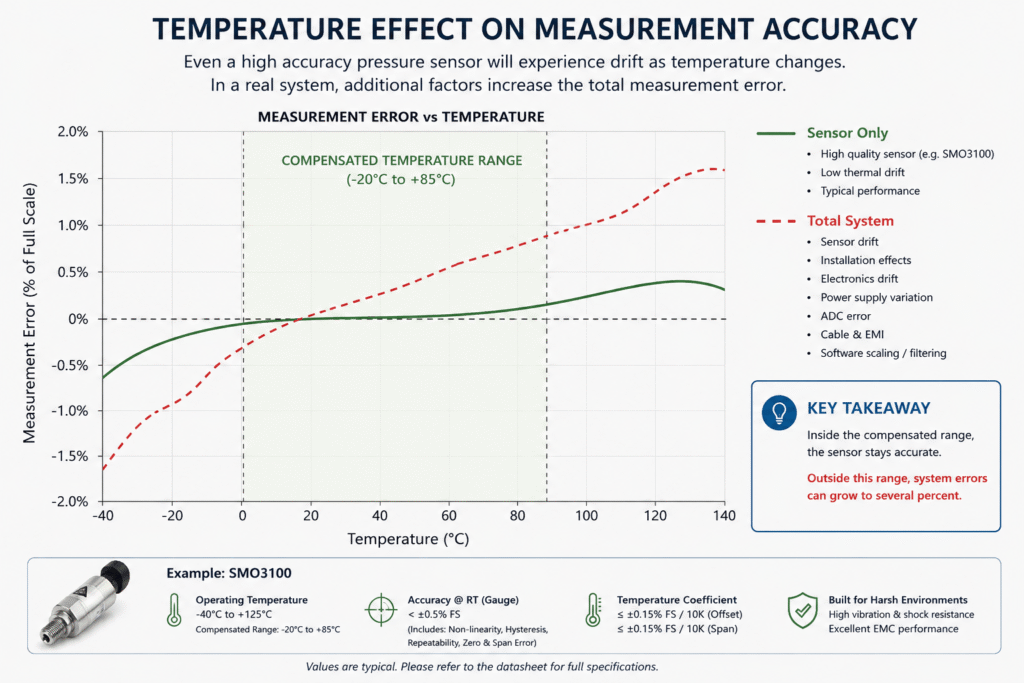
For example, the SMO3100 series is designed to operate at temperatures up to +125°C, but its full specified accuracy is guaranteed only within its compensated temperature range of -20°C to +85°C. The datasheet also specifies temperature coefficients of up to 0.15% FS per 10°C for both Zero Offset and Span.

The message is simple.

Even when a pressure sensor is designed for harsh environments, temperature remains a critical factor that must be considered during system design.

This is not a limitation of a particular pressure sensor.

It’s physics.

Figure 1 – The Effect of Temperature on Measurement Accuracy

The green curve represents the performance of the pressure sensor itself, while the red curve illustrates the overall measurement error of the complete system. Even when the sensor operates within its specified performance limits, factors such as temperature, mechanical installation, electronics, cabling, and control software can increase the total measurement error. Achieving accurate measurements therefore requires careful design of the entire measurement chain – not simply selecting a sensor based on its Accuracy specification.

Proper Installation Is Part of Measurement Accuracy

By the time a pressure sensor leaves the factory, it has already been calibrated and tested to ensure it meets the manufacturer’s specified performance.

However, once it is installed in your system, the quality of the measurement is no longer determined by the manufacturer alone.

The installation itself becomes part of the measurement system.

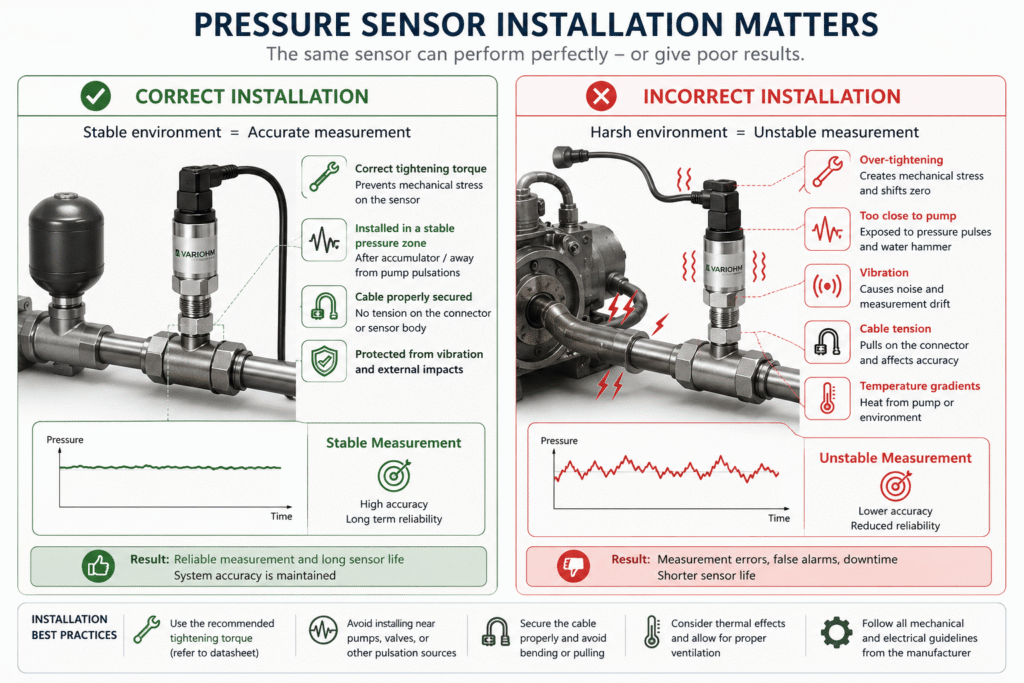
For example, overtightening a pressure sensor can introduce mechanical stresses into the sensor body and diaphragm. In most cases, the sensor will not be damaged, but these stresses can cause small shifts in Zero Offset or affect overall measurement performance.

The installation location is equally important.

A pressure sensor mounted directly at the outlet of a hydraulic pump will experience pressure pulsations and vibration that are very different from those seen by a sensor installed downstream of an accumulator or at some distance from the pressure source.

As a result, two identical pressure sensors can produce different measurement results – not because the sensors are different, but because they operate under different installation conditions.

For this reason, when designing a new system or troubleshooting an existing one, it is just as important to ask how the pressure sensor was installed as which pressure sensor was selected.

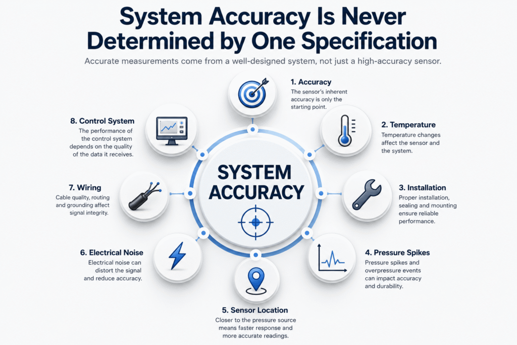
Figure 2 – Installation Also Affects Measurement Accuracy

Two identical pressure sensors can produce different measurement performance simply because they are installed differently. Overtightening, mounting the sensor close to a hydraulic pump, excessive vibration, cable strain, or an unsuitable installation location can all influence the measured value – even when the pressure sensor itself is operating exactly as specified. Accurate measurements therefore depend not only on the quality of the sensor, but also on proper installation and sound system design.

Sensor Sees

When designing a system, it is common practice to select a pressure sensor based on the system’s operating pressure.

For example:

The system operates at 250 bar.

So, a 250 bar pressure sensor is selected.

At first glance, that seems perfectly reasonable.

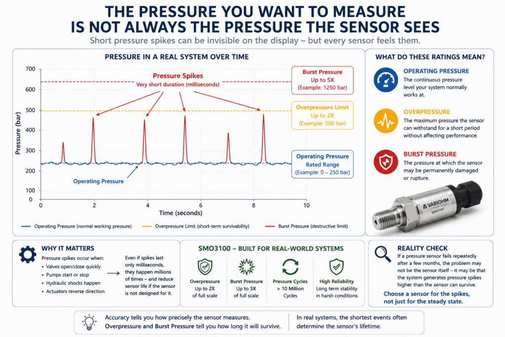
In real-world systems, however, pressure is rarely constant.

Every rapid valve opening or closing, every pump speed change, and sometimes even system startup or shutdown can generate brief pressure spikes.

These events may last only a few milliseconds.

In many cases, the operator will never see them on the control system display.

But the pressure sensor sees every single one of them.

The Two Datasheet Specifications That Are Often Overlooked

When reading a pressure sensor datasheet, most engineers focus on:

  • Accuracy
  • Pressure Range
  • Output Signal

However, two of the most important specifications for long-term reliability are often overlooked:

Overpressure

and

Burst Pressure

These are not marketing specifications.

They describe the sensor’s ability to survive abnormal pressure events that occur naturally in real-world systems.

For example, the SMO3100 series is designed to withstand transient pressures of up to twice its rated pressure (Overpressure), a Burst Pressure of up to five times the rated pressure, and more than 10 million pressure cycles.

These specifications describe more than measurement performance.

They also indicate the sensor’s long-term mechanical durability.

Accuracy Doesn’t Matter If the Sensor Doesn’t Survive

Imagine two pressure sensors.

Both have:

  • ±0.5% Accuracy
  • The same analog output
  • The same pressure range

On paper, they appear identical.

But if one sensor is designed to withstand high pressure spikes while the other is not, they may perform very differently after only a few months in a hydraulic system.

One continues to provide stable, reliable measurements.

The other may begin to develop offset or measurement drift – even though the system has never exceeded its continuous operating pressure.

That is why experienced engineers do not select a pressure sensor based solely on its pressure range or accuracy specification.

They choose a sensor based on how the entire system actually operates.

Figure 3 – Operating Pressure Is Only Part of the Story

In real-world systems, pressure is rarely constant. Valve switching, pump operation, and rapid flow changes generate brief pressure spikes that may never appear on the control system display – yet the pressure sensor experiences every one of them. For this reason, selecting a pressure sensor involves more than matching the operating pressure. Overpressure and Burst Pressure ratings are equally important, as they determine the sensor’s ability to withstand transient overloads and deliver reliable measurements over years of operation.

A Fast Sensor Does Not Guarantee a Fast Measurement

When selecting a pressure sensor, many engineers look at its Response Time.

The shorter the response time, the “faster” the sensor is considered to be.

But this is another common misconception.

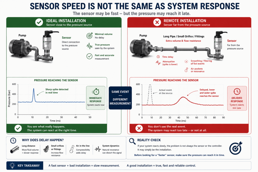
A pressure sensor does not measure the pressure inside the pump or somewhere within the hydraulic line.

It measures only the pressure that actually reaches the sensing element.

If the pressure travels through a long tube, a small orifice, an adapter, a needle valve, or an intermediate volume before reaching the sensor, the hydraulic signal itself is delayed before it ever reaches the diaphragm.

In other words, even if the pressure sensor has a response time of just one millisecond, the entire measurement system may respond tens of milliseconds later.

The sensor is not “slow.”

The pressure simply arrived late.

That is why, in dynamic applications, the installation location can be just as important as the sensor’s specifications.

The Further the Sensor Is from the Pressure Source, the Further Behind Reality It Becomes

In many systems, pressure sensors are installed wherever it is most convenient from a mechanical or electrical standpoint.

From a measurement perspective, however, that is not always the best location.

When a pressure sensor is mounted away from the pressure source, the hydraulic signal must travel through a volume of liquid or gas before reaching the sensing element.

During that journey, several effects may occur:

  • Time delay
  • Attenuation of pressure fluctuations
  • Natural filtering of fast pressure events
  • Trapped air bubbles
  • Hydraulic resonance within the piping

As a result, the control system may never “see” the actual pressure event.

Instead, it receives a delayed and smoothed version of reality.

Figure 4 – A Fast Pressure Sensor Does Not Guarantee a Fast System Response

When a pressure sensor is installed close to the pressure source, it can detect rapid pressure changes almost in real time. However, a long tube, a restrictive orifice, adapters, or trapped air can delay and dampen the pressure signal before it ever reaches the sensor. As a result, if the control system responds slowly, the problem may not be the sensor’s response time – the pressure itself may simply be arriving too late.

Before Selecting a Pressure Sensor – Ask the Right Questions

When selecting a pressure sensor, it’s easy to compare datasheets.

Accuracy.

Pressure Range.

Output Signal.

Price.

As we’ve seen throughout this article, however, these are only part of the decision.

In practice, selecting the right pressure sensor begins with understanding the application – and only then choosing the sensor.

Before making your final decision, work through the following checklist.

Engineer’s Checklist

☐ Have I selected the correct pressure reference (Gauge / Absolute / Differential)?

☐ Is the measuring range suitable for both the normal operating pressure and potential pressure spikes?

☐ Have I checked the Overpressure and Burst Pressure ratings?

☐ Does the system’s operating temperature fall within the sensor’s compensated temperature range?

☐ Will the installation location expose the sensor to vibration, heat, or pressure pulsations?

☐ Is the pressure sensor installed as close as possible to the actual measurement point?

☐ Does the mechanical installation, thread connection, and sealing follow the manufacturer’s recommendations?

☐ Has the entire measurement chain – from the pressure sensor to the control system – been designed to preserve the required measurement accuracy?

If you answered “No” to even one of these questions, it may be worth reviewing the system design before assuming the pressure sensor is at fault.

Conclusion

The Accuracy specification at the top of a datasheet is important.

But it is only the starting point.

In a real-world application, measurement quality is influenced by many factors, including environmental conditions, installation practices, pressure dynamics, temperature, signal transmission, and the design of the entire control system.

When designing a new system or troubleshooting an existing one, the real question is not:

“How accurate is the pressure sensor?”

The better question is:

“Has the entire measurement chain been designed to allow the pressure sensor to achieve its specified performance?”

That is why experienced engineers do not select a pressure sensor based solely on its Accuracy specification.

They evaluate the entire application.

Because in the end, a reliable measurement system is not built simply by selecting high-quality components.

It is built by understanding how those components work together.

Accuracy is a characteristic of the pressure sensor.

Measurement reliability is a characteristic of the entire system.

Engineering Example – Why Two Pressure Sensors with the Same Accuracy Performed Very Differently

Consider a hydraulic system operating at a continuous pressure of 250 bar.

Based on the datasheet alone, an engineer might select a 0-250 bar pressure sensor with an Accuracy of ±0.5% FS.

On paper, that appears to be an excellent choice.

Now let’s look at what actually happens in the application.

Operating Conditions

  • Continuous operating pressure: 250 bar
  • Rapid valve switching
  • Pump starts and stops
  • Short-duration pressure pulsations during operation
  • Changing ambient temperatures

A high-speed data logger revealed transient pressure spikes of:

430-470 bar

lasting 2-5 milliseconds.

These events never appeared on the PLC display.

The pressure sensor, however, experienced every one of them.

Two Pressure Sensors

Sensor A

✔ Accuracy: ±0.5% FS

However:

  • Relatively limited Overpressure capability

Sensor B – SMO31H2-PLd

✔ Accuracy: < ±0.5% FS

✔ Overpressure up to 2× Full Scale

✔ Burst Pressure up to 5× Full Scale

✔ More than 10 million pressure cycles

✔ Shock: 1000 G

✔ Vibration: 25 G

✔ Operating temperature up to 125°C

These specifications are taken directly from the SMO31H2-PLd technical datasheet.

After One Year of Operation

Sensor A

✖ Developed a measurement offset

✖ Output became unstable

✖ Required replacement

Sensor B

✔ Continued operating normally

✔ Accuracy remained within specification

✔ No measurable change in performance

What Really Happened?

The two pressure sensors offered nearly the same Accuracy specification.

The difference was not measurement accuracy.

It was their ability to withstand the actual operating conditions.

The application generated transient pressure spikes, vibration, mechanical shock, and temperature variations that extended well beyond the basic operating pressure specification.

The sensor designed for those conditions continued to perform as expected.

The other did not.

The problem was never the Accuracy specification.

The problem was assuming the system would behave like a laboratory test.

🧩 Further Reading – Measurement as a System

This article is part of an engineering series exploring how reliable measurement depends on proper system design rather than on a single sensor component.

Before diving deeper into industrial temperature sensing, you may also find the following articles in the series useful:

  • VARIOHM Group – When Measurement Is a System, Not a Component
  • How to Select Sensors for Harsh Environments: An Engineering Guide for Reliable Measurement in the Real World
  • VARIOHM Position Sensors – Engineering Position as a System, Not Just a Signal
  • Industrial Pressure Sensors – When Pressure Measurement Becomes a System Engineering Challenge
  • Industrial Temperature Sensors – When Temperature Measurement Becomes a System Engineering Challenge
  • Choosing the Right Linear Position Sensor: Why Stroke Length Is Only the Beginning
  • Contactless Rotary Position Sensors – Why More and More Systems Are Moving to Non-Contact Sensing
  • Choosing the Right Temperature Probe Mounting
  • How Differential Pressure (ΔP) Can Reveal Problems Long Before a System Shuts Down
  • Your Temperature Sensor Says 80°C. The Real Hot Spot Could Already Be at 130°C
  • Measuring Pressure Without Temperature Is Only Half the Picture
  • Does Your Thermal Protector Really Solve the Problem? Or Just Give the System Another Chance to Fail?
  • Why a Linear Position Sensor Shouldn’t Be Selected by Stroke Alone
  • Your System Has Powered Up – But Does It Know Where It Is? Absolute Position Sensors vs. Homing

Choosing the Right Pressure Sensor Family

Not every application requires the same type of pressure sensor. Rather than selecting a sensor based solely on its Accuracy specification, start by understanding the requirements of your application.

General Industrial Applications

The EPT3100 and SMO3100 series are designed for a wide range of hydraulic, pneumatic, and industrial applications. They offer broad pressure ranges, stainless steel construction, and excellent resistance to demanding operating environments.

High-Pressure Applications

For applications operating at extremely high pressures, the EPT31HP and SMO3100 series provide measurement ranges of up to 5,000 bar while maintaining outstanding mechanical durability.

Hydrogen Systems

Hydrogen applications place unique demands on materials, sealing technology, and safety. The EPT31H2, SMO31H2, and EPT92H2 series have been specifically developed for hydrogen service and are available with EC79 and EC406 approvals.

Functional Safety Systems

Where pressure measurement is part of a safety-critical function, the SMO31H2-PLd and SMO3100PLd series are designed for SIL2 and PL d applications. They incorporate diagnostic capabilities and reliability data suitable for functional safety systems.

Compact and Motorsport Applications

Where installation space is limited, the EPT1200, EPT1400, and EPT1500 series provide compact, lightweight solutions without compromising performance.

CANbus, Vehicle and IoT Applications

Applications requiring digital communication or low power consumption can benefit from dedicated models such as the EPT31CN (CANopen / J1939) and the EPT31LE, which is optimized for battery-powered and IoT systems.

There is no such thing as the best pressure sensor.

There is only the pressure sensor that is best suited to the application.

Selecting the right sensor begins with understanding the operating conditions, pressure dynamics, environmental requirements, and functional safety considerations. Only then should the appropriate sensor family be selected.

Application Recommended Sensor Series
General Industrial EPT3100, SMO3100
High Pressure EPT31HP, SMO3100
Hydrogen Systems EPT31H2, EPT92H2, SMO31H2
Functional Safety (SIL2 / PL d) SMO3100PLd, SMO31H2-PLd
Compact / Motorsport EPT1200, EPT1400, EPT1500
CANbus / IoT EPT31CN, EPT31LE

Frequently Asked Questions (FAQ)

Does a pressure sensor with an Accuracy of ±0.5% always measure within ±0.5%?

No.

The Accuracy specification describes the performance of the pressure sensor itself under the conditions defined by the manufacturer. In practice, overall measurement accuracy is also influenced by temperature, installation quality, vibration, electrical noise, power supply stability, the measurement chain, and the control system.


Should I always choose the most accurate pressure sensor available?

Not necessarily.

In many applications, factors such as vibration resistance, Overpressure capability, pressure cycling, operating temperature range, and suitability for the application are more important than a small difference in the specified Accuracy.


Can the PLC affect measurement accuracy?

Yes.

Even if the pressure sensor provides a highly accurate output, the final measurement also depends on the PLC’s analog input module, ADC resolution, calibration accuracy, electrical noise, and the way the software processes the signal.

A measurement system is only as accurate as its weakest link.


What is an ADC, and how does it affect measurement accuracy?

An ADC (Analog-to-Digital Converter) converts the analog output of the pressure sensor into the digital values used by the controller.

If the ADC has limited resolution or accuracy, small pressure changes may not be represented correctly, even when the pressure sensor itself is highly accurate.


Can electromagnetic interference (EMI) affect pressure measurements?

Yes.

Sensor cables routed near electric motors, variable frequency drives (VFDs), relays, or high-voltage wiring can pick up electrical noise. This may result in unstable readings or random fluctuations.

Proper cable routing, grounding, and, where necessary, shielded cables are essential for reliable measurements.


Is a longer sensor cable always acceptable?

Longer cables increase the risk of electrical interference and voltage drop.

In larger systems, cable routing should be planned carefully, keeping sensor wiring as far as practical from sources of electromagnetic interference.


Does sensor location really affect response time?

Yes.

Even a very fast pressure sensor cannot respond immediately if the pressure reaches it through a long tube, a restrictive fitting, or an intermediate volume.

In dynamic applications, installation location can be just as important as the sensor’s specifications.


What is the difference between Overpressure and Burst Pressure?

Overpressure is the maximum temporary pressure that the sensor can withstand without damage.

Burst Pressure is the pressure at which mechanical failure of the sensor may occur.

Both specifications are particularly important in hydraulic systems where short-duration pressure spikes are common.


Is it better to select a pressure sensor with a higher pressure range “just to be safe”?

Not always.

Selecting a pressure range that is significantly higher than required may reduce measurement resolution within the normal operating range.

The goal is to choose a sensor that can safely withstand both the operating pressure and expected pressure spikes without compromising measurement performance.


Can a pressure sensor be damaged even if the normal operating pressure never exceeds its rating?

Yes.

Short-duration pressure spikes, continuous vibration, or poor installation practices can affect long-term sensor performance, even when the average operating pressure remains within the specified range.


Does measurement accuracy depend only on the pressure sensor?

No.

Measurement accuracy depends on the entire measurement chain, including the pressure sensor, wiring, power supply, PLC, ADC, software, environmental conditions, and installation quality.

This is why good system engineering is just as important as selecting the right pressure sensor.


Which is more important: sensor Accuracy or system Accuracy?

Both are important, but ultimately system accuracy is what determines measurement performance.

A high-quality pressure sensor is essential, but it is only one part of the solution. Stable, reliable, and accurate measurements can only be achieved when the entire measurement chain, from the pressure sensor to the PLC, has been properly designed.

Common Abbreviations

Abbreviation Meaning
ADC Analog-to-Digital Converter
BFSL Best Fit Straight Line
CAN Controller Area Network
EMC Electromagnetic Compatibility
EMI Electromagnetic Interference
FS Full Scale
IP Ingress Protection
PLC Programmable Logic Controller
PL d Performance Level d
RT Room Temperature
SIL Safety Integrity Level
TC Temperature Coefficient

Glossary

Accuracy

The degree to which a pressure sensor’s measured value matches the actual pressure. It is important to remember that Accuracy usually refers to the performance of the sensor itself and does not necessarily represent the accuracy of the complete measurement system.

ADC (Analog-to-Digital Converter)

An electronic device that converts the analog output of a pressure sensor into a digital signal used by a PLC or control system. The performance of the ADC has a direct impact on overall measurement quality.

Ambient Temperature

The temperature of the environment surrounding the pressure sensor. This may differ significantly from the temperature of the process fluid.

BFSL (Best Fit Straight Line)

A method of calculating accuracy and non-linearity by comparing the sensor’s output to an ideal best-fit straight line. Many manufacturers specify Accuracy using this method.

Burst Pressure

The pressure at which permanent mechanical failure or irreversible damage to the pressure sensor may occur.

Compensated Temperature Range

The temperature range over which the manufacturer guarantees the specified measurement performance and accuracy.

Differential Pressure

The measurement of the pressure difference between two points in a system rather than pressure relative to atmospheric pressure.

EMI (Electromagnetic Interference)

Unwanted electromagnetic disturbances that can affect electrical signals, resulting in unstable readings or increased measurement noise.

Gauge Pressure

Pressure measured relative to atmospheric pressure. This is the most common pressure reference used in industrial applications.

Hysteresis

The difference between the sensor output during increasing pressure and decreasing pressure at the same pressure point.

Linearity

The degree to which the sensor’s output follows an ideal straight-line relationship throughout its measurement range.

Offset (Zero Offset)

The error at the sensor’s zero-pressure point, where the output differs from the expected zero value.

Operating Pressure

The continuous pressure at which a system is designed to operate during normal conditions.

Overpressure

The maximum temporary pressure that a pressure sensor can withstand without damage or permanent degradation of its measurement performance.

PLC (Programmable Logic Controller)

An industrial controller that receives the sensor signal, processes it, and controls the operation of the system.

Pressure Cycle

One complete increase and decrease in pressure. The number of pressure cycles a sensor can withstand is an important indicator of its expected service life.

Pressure Spike

A very short-duration pressure transient, typically lasting only a few milliseconds. Although brief, repeated pressure spikes can significantly affect sensor life.

Repeatability

The ability of a pressure sensor to produce the same output when the same pressure is measured repeatedly under identical conditions.

Response Time

The time required for a pressure sensor to respond to a pressure change and reach its specified output value.

Resolution

The smallest change in pressure that can be detected by the measurement system. Overall resolution depends on both the pressure sensor and the ADC.

Sensor Drift

A gradual change in sensor performance over time caused by aging, temperature, or environmental conditions.

SIL (Safety Integrity Level)

A measure of safety performance defined by IEC 61508 for safety-related systems.

PL d (Performance Level d)

A functional safety performance level defined by ISO 13849-1 for evaluating the reliability of safety-related control systems.

Span

The difference between the lower and upper limits of the pressure sensor’s measurement range. Span errors affect the slope of the measurement curve.

Temperature Coefficient (TC)

A measure of how the sensor’s performance changes as temperature varies.

Transducer

A device that converts a physical quantity, such as pressure, into an electrical signal that can be measured and processed.

Zero Shift

A change in the sensor’s zero point caused by temperature, mechanical stress, aging, or other environmental influences.

Tags: Variohm

Related Articles

How to Select Sensors for Harsh Environments: An Engineering Guide for Reliable Measurement in the Real World

18/02/2026amironicLTD

Spring-Loaded Linear Position Sensors for Space-Limited and Harsh Environments

22/01/2026amironicLTD

Tailor-Made Solutions for Accurate and Reliable Temperature Sensing

24/06/2025amironicLTD

Recent Posts

  • How Does an INS Algorithm Really Work?
  • Your Pressure Sensor May Be Accurate. Your Measurement May Not Be – Why a ±0.5% Accuracy Specification Doesn’t Guarantee a ±0.5% Measurement
  • From IMU to INS: How a Tactical Navigation System Is Really Built
  • What Can We Learn from 40-Year-Old Hydraulic-Magnetic Circuit Breakers Still in Service?
  • Why Did Your Footswitch Fail After Just Six Months – Even Though It Was Rated for One Million Operations?

Categories

  • Air Switch
  • Circuit Breakers
  • Elapsed Time Indicator
  • Feedthrough
  • Footswitches
  • Gears & Transmission
  • Hour Meters
  • Infra Red Switches
  • INFRARED LAMPS
  • Low Noise Inertial MEMS
  • Mechanics
  • MEMS Gyroscope
  • MEMS Inertial
  • Microelectronics
  • Motors
  • Position Sensors
  • Power Supply
  • Pressure Sensors
  • Pressure Switch
  • Temperature Sensors
  • Tungsten and Molybdenum
  • Uncategorized
  • Vacuum Switches

Quick Contact

Fill out the form and our representatives will return to you

    Name (required)

    Email (required)

    Phone

    Message

    This site is protected by reCAPTCHA and the Google
    Privacy Policy and
    Terms of Service apply.

    Amironic Ltd.

    3 Rabinovich Street, Petah Tikva 4928144 , Israel. Tel: +972-3-9047744 E-mail: office@amironic.co.il
    Email
    Facebook
    Twitter
    LinkedIn
    YouTube
    Press on the ISO Certificate below for download
    ISO 9001:2015 Certification
    • MEMS Inertial
    • Circuit Breakers
    • Footswitches
    • Mechanical & Transmisions
    • Sensors
    • Motors
    • Electronics
    • Hand Control
    • Power Solutions

    News

    • How Does an INS Algorithm Really Work?
    • Your Pressure Sensor May Be Accurate. Your Measurement May Not Be – Why a ±0.5% Accuracy Specification Doesn’t Guarantee a ±0.5% Measurement
    • From IMU to INS: How a Tactical Navigation System Is Really Built
    • What Can We Learn from 40-Year-Old Hydraulic-Magnetic Circuit Breakers Still in Service?
    • Why Did Your Footswitch Fail After Just Six Months – Even Though It Was Rated for One Million Operations?
    About AmironicContactעברית
    © 2022 Amironic All rights reserved. All Trademarks are the property of their respective owners.
    • Increase Font
    • Decrease Font
    • Black & White
    • Inverse Colors
    • Highlight Links
    • Regular Font
    • Reset