flagעברית
flagEnglish
3 Rabinovich St., Petah-Tikva, Israel
+972 3 9047744
office@amironic.co.il
Facebook
Twitter
LinkedIn
YouTube
  • Products
    • MEMS Inertial
      • Gyros & Accels
      • IMU
      • Inertial Navigation
      • AHRS
    • Circuit Breakers
      • Airpax Circuit Breakers
      • Electronic Circuit Breakers
      • Aircraft Circuit Breakers
      • Thermal Circuit Breakers
      • Sealing Solutions & Guards
    • Footswitches
      • Pedals & Bellows
      • USB
      • Air Switches
      • Medical
      • Modular Bases System
      • Industrial
      • Foot Potentiometers
      • Wireless
    • Mechanical & Transmisions
      • Gears
      • Sealing Solutions
      • Gearboxes
      • Couplings
      • Shafts & Bearings
      • Fasteners
      • Mechanical & Springs
      • Linear Motion
      • Anti-Vibration
    • Sensors
      • Thermostats
      • Temperature
      • Position
      • Pressure
      • Speed
      • Level Sensor
      • Load Cells
      • Flex Sensors
      • Membrane Potentiometer
    • Motors
      • Geared DC
      • Brushless DC
      • Step Motors with Gearbox
      • Torque Motors & Brushless Servo
      • DC Motors
    • Electronics
      • Xenon & IR Lamps
      • Counters & Meters
      • Microelectronics Packaging
      • Waterproof Switches
      • Micro Switches
    • Hand Control
      • Operator Controls (JOYSTICK)
      • Electrical
      • Pneumatic (Medical)
      • USB Hand Control
      • Air Push Button
      • Pressure Switch
      • IR Switch
    • Power Solutions
      • Rugged & Military Power Supply
      • Input Power Protection
      • Sealed Military Power Adaptor
      • Triple Output Military Power Supply Series – up to 250 W
    • Materials
      • Molybdenum and Advanced Alloys (TZM, MOLA, HCT)
      • Tungsten (Wolfram) and Advanced Alloys – High-Performance Materials for Extreme Conditions
      • Materials for Gears
  • Shop
  • Companies
  • About Amironic
  • News
  • Contact
Product was added to your cart

Cart

waze

Why Military Power Distribution Is Becoming the New Battlefield

Circuit Breakers30/07/2026amironicLTD

A decade ago, the primary challenge was to build smarter systems.

Today, the challenge is to make all of them work together.

A modern combat vehicle may operate an AESA radar, electronic warfare systems, EO/IR sensors, AI computers, satellite communications, counter-UAS systems, and even directed-energy weapons at the same time.

But all of these systems have one thing in common.

They depend on the same power system.

They compete for the same energy source, generate high inrush currents, remain sensitive to voltage drops, and must continue operating under vibration, shock, and extreme environmental conditions.

In other words, the battle is no longer taking place only between weapon systems.

It is also taking place inside the power distribution system.

More and more system engineers are discovering that the platform’s performance limit is not necessarily the processor, the radar, or the algorithm, but its ability to deliver stable, protected, and continuous power to every mission-critical system.

This is why Military Power Distribution has evolved in recent years from a quiet infrastructure challenge into one of the most important engineering disciplines in the design of modern military platforms.
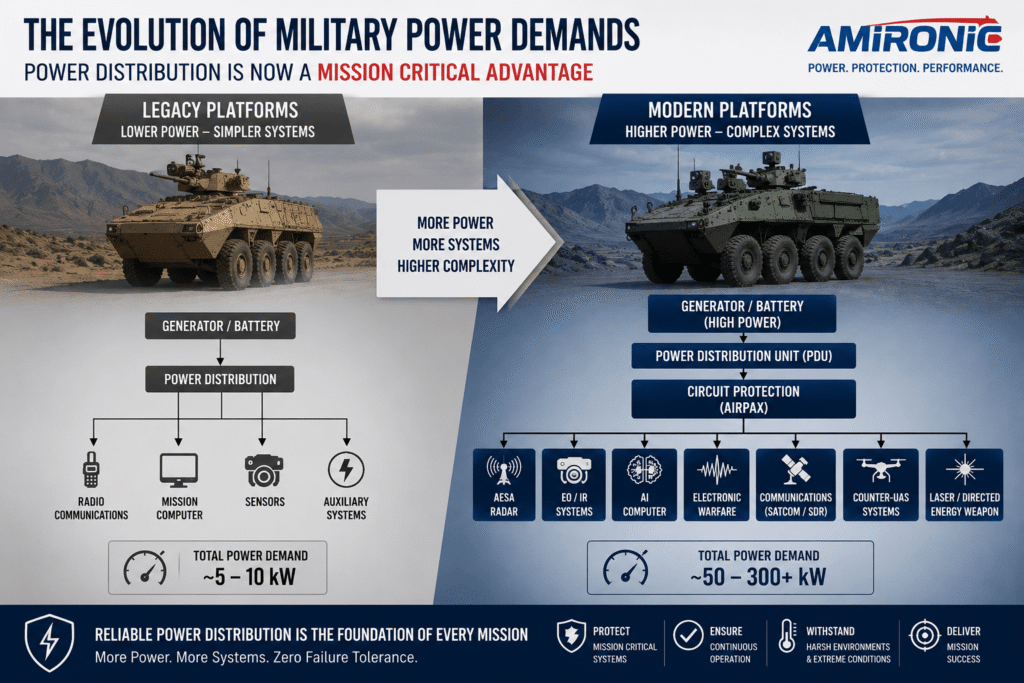
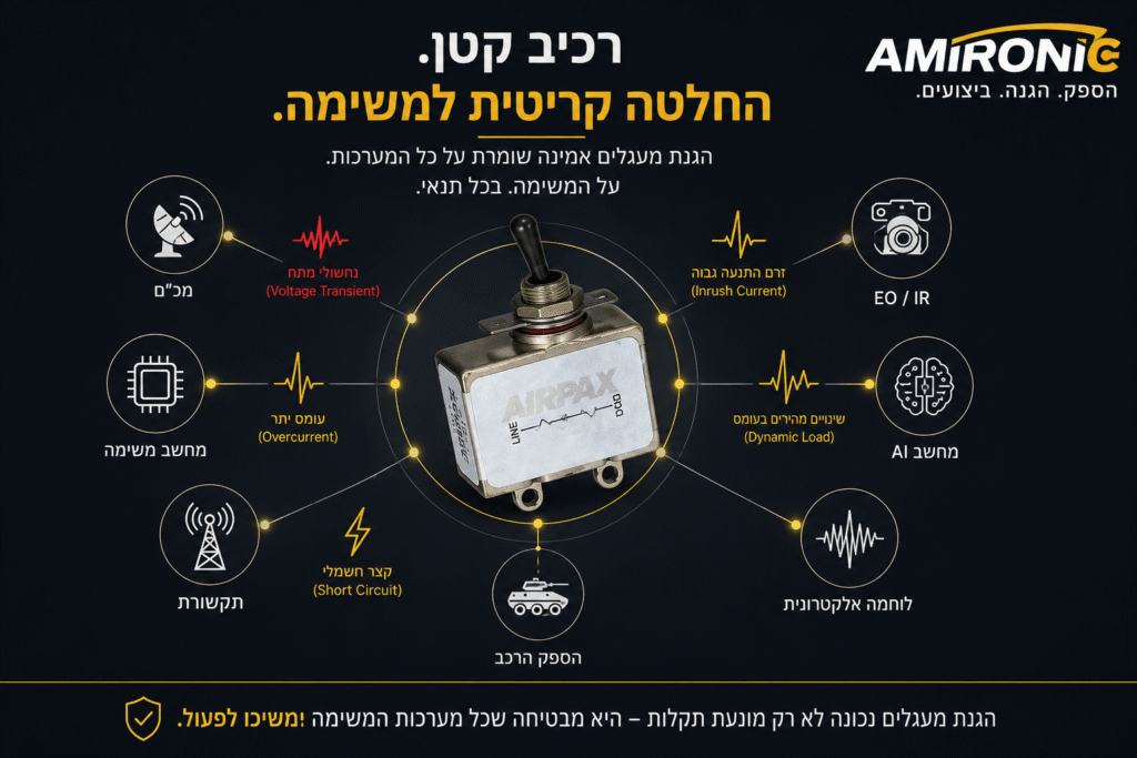
Figure 1: As the number of onboard systems and overall electrical power demand increase, the importance of a well-designed power distribution architecture grows accordingly. Today, a single fault within the power distribution system can simultaneously disable multiple mission-critical systems and significantly reduce operational readiness.

More Systems, More Power, More Risk

Modern military platforms not only consume more electrical power, they also behave very differently from an electrical perspective.

In the past, most loads were relatively stable and predictable. Today, an AESA radar may transition from standby to full power in a fraction of a second, an electronic warfare system can begin transmitting at maximum output almost instantly, and an AI computer may significantly increase its power consumption depending on the computational workload.

At the same time, the vehicle itself must continue operating during engine starts, weapon firing, rapid acceleration, severe vibration, temperature fluctuations, and other harsh environmental conditions.

As a result, the military power distribution network is now expected to handle operating conditions that rarely existed together on a single platform in the past.

Some of the most significant challenges include:

  • High Inrush Current
  • Voltage Drops
  • Voltage Transients and Surges
  • Electromagnetic Interference (EMI/EMC)
  • Heating of power components and electrical connectors
  • Rapidly changing dynamic loads
  • High system availability with no tolerance for unexpected downtime

When every one of these systems is mission-critical, even a minor disturbance in the power distribution network can result in the loss of operational capability.


Not Every Failure Starts in the System Itself

When a radar unexpectedly reboots, an EO/IR sensor freezes, or the mission computer performs an unexplained reset, the first assumption is usually a software bug or a failure within the electronic equipment.

In reality, many of these failures originate in the power distribution system.

An improperly selected circuit breaker, a brief voltage drop during the startup of a high-power load, a DC/DC converter unable to respond to rapid load changes, or an input protection device that is not suited to the operating environment can all produce symptoms that initially appear to be failures within the mission system itself.

This is precisely why system engineers now place much greater emphasis on power distribution architecture during the earliest stages of system design, rather than waiting until problems emerge during integration or field testing.

Generator / Battery
        ↓
Power Distribution Unit
        ↓
Circuit Protection
        ↓
DC/DC Converter
        ↓
Mission Computer
Radar
EO/IR
Communications
Figure 2: Typical power architecture of a modern military platform. Every component in the power chain affects the next, meaning that a single electrical event, such as a high inrush current, voltage drop, or voltage transient, can impact multiple mission systems simultaneously. A well-designed power distribution architecture and properly selected circuit protection are essential to ensuring the reliability and availability of the entire platform.

Circuit Protection – Much More Than Just a Circuit Breaker

When people think of a circuit breaker, they often picture a simple device whose only purpose is to disconnect a circuit during an overload or short circuit.

In modern military platforms, its role is far more sophisticated.

A circuit breaker is one of the first lines of defense against electrical faults, but it must also allow the system to operate reliably while handling high inrush currents, rapid load changes, and other transient electrical events without unnecessary interruptions.

In other words, a poorly selected circuit breaker may provide excellent protection while being overly sensitive in normal operation. The result is nuisance tripping at the exact moment the mission system is expected to perform.

This is one of the reasons why military engineers do not select a circuit breaker based solely on its current rating. They also evaluate the trip curve, inrush current characteristics, interrupt rating, operating temperature range, resistance to shock and vibration, mechanical and electrical endurance, and compliance with applicable military standards.

In many cases, these parameters determine whether a mission system continues operating as intended or performs an unexpected reset at the worst possible moment.


Why Has Airpax Become the Preferred Choice for Military Platforms?

For decades, Airpax circuit breakers have been integrated into military, aerospace, and naval platforms around the world. Their reputation is built not only on manufacturing quality, but also on the ability to offer a wide range of trip curves, current ratings, mounting configurations, and performance characteristics, allowing system engineers to match circuit protection to the actual behavior of the load rather than simply selecting a current rating.

In platforms where radar systems, mission computers, motors, pumps, and electronic warfare equipment operate simultaneously, the difference between the right circuit breaker and the wrong one can be the difference between a highly reliable system and one plagued by intermittent shutdowns that are extremely difficult to diagnose.

For this reason, selecting a circuit breaker is no longer just an electrical protection decision. It is an engineering decision that directly affects system reliability, operational availability, and ultimately, mission success.

Figure 3: A circuit breaker may appear to be a small and simple component, but in military platforms it is a critical part of the power distribution architecture. Proper circuit breaker selection ensures reliable operation during high inrush currents, voltage transients, and rapidly changing dynamic loads, helping mission-critical systems remain operational when they are needed most.

Not Every Circuit Breaker Is Right for Every System

One of the most common mistakes in power system design is assuming that two circuit breakers with the same current rating will behave identically.

In reality, two 20 A circuit breakers can respond very differently under the same operating conditions.

The reason is simple: the current rating is only one of many parameters that determine how a circuit breaker performs. Response time, trip curve, inrush current capability, ambient temperature characteristics, and interrupt rating all have a direct impact on overall system reliability.

In military platforms, where motors, pumps, radar systems, and mission computers often operate simultaneously, selecting the wrong circuit breaker characteristics can lead to intermittent trips that are not caused by an actual fault, but by a mismatch between the circuit breaker and the load profile.

In many cases, simply replacing the circuit breaker with one that has the appropriate trip curve can eliminate a problem that had been misdiagnosed for months as a fault in the mission computer, DC/DC converter, or even the software itself.


Beyond Protection – Reliability for Decades

Military platforms are not designed to operate for just a few years. Many remain in service for decades, accumulating thousands of operating hours while being exposed to vibration, shock, extreme temperatures, humidity, and other harsh environmental conditions.

For this reason, a circuit breaker is evaluated not only for its ability to interrupt fault currents, but also for its long-term performance stability, resistance to mechanical stress, environmental durability, and its ability to maintain consistent protection characteristics throughout its service life.

This is one of the reasons why Airpax circuit breakers have been used for decades in military, aerospace, and naval platforms worldwide. They were engineered for applications where reliability is not an advantage – it is a fundamental requirement.


When Mission Success Depends on the Smallest Details

In modern combat platforms, mission success is not determined solely by the performance of the radar, the quality of the sensors, or the processing power of the mission computer.

Sometimes, the difference between a system that continues operating and one that performs an unexpected reset at the most critical moment comes down to a single component selected correctly during the design phase.

For this reason, designing a robust power distribution architecture and selecting the appropriate circuit protection devices are not merely aspects of electrical engineering. They are fundamental to the reliability, availability, and operational effectiveness of the entire platform.

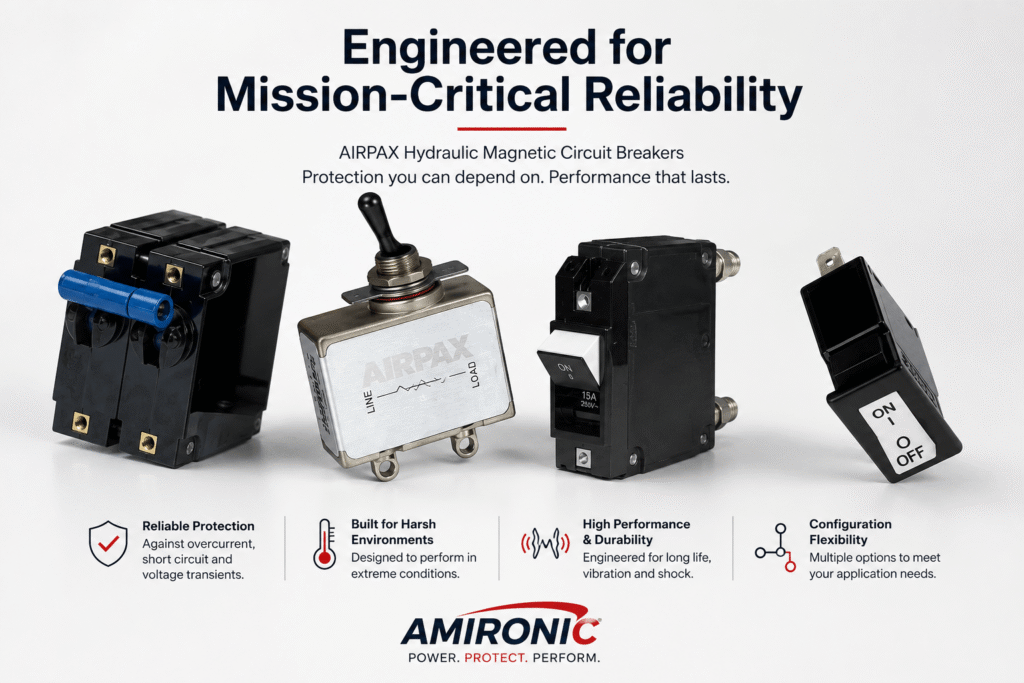
Figure 4: Airpax circuit breakers are available in a wide range of series and configurations, allowing engineers to match current ratings, trip curves, mounting requirements, and environmental performance to the specific application. Selecting the right circuit breaker characteristics is one of the most important factors in ensuring the long-term reliability and availability of a platform’s power distribution system.

Why 100 Amps Does Not Always Mean 100 Amps

A 100 A rating on a circuit breaker does not guarantee identical performance in every system or operating environment. The rated current is determined under standardized test conditions, while in a real platform the circuit breaker is installed inside a crowded enclosure, surrounded by heat-generating components, cables, connectors, and terminals that also warm up under load. As ambient temperature increases, the thermal margin of the entire power distribution system decreases, and thermal derating may become necessary.

With conventional thermal circuit breakers, ambient temperature can directly influence trip performance. A breaker operating in a hot environment may trip sooner than the same breaker operating at room temperature. In contrast, hydraulic-magnetic circuit breakers, such as many Airpax product families, use a tripping mechanism that is significantly less affected by ambient temperature. This allows for more predictable and consistent trip characteristics across a wide range of operating conditions.

However, even with hydraulic-magnetic circuit breakers, overall system temperature cannot be ignored. Cable size, connection quality, installation density, heat dissipation, and enclosure temperature all influence the system’s ability to carry high current continuously.

The real engineering question is not simply:

Is the circuit breaker rated for 100 A?

It is:

Can the entire power distribution path continuously carry 100 A under the platform’s actual operating temperature and installation conditions?

That is the difference between selecting a circuit breaker from a catalog and engineering a power distribution system that will continue to perform reliably in the field.

Figure 5: Conceptual illustration of how ambient temperature can affect the continuous current-carrying capability of a power distribution system. A circuit breaker rated at 100 A does not necessarily guarantee continuous operation at that current under all temperatures or installation conditions. While Airpax hydraulic-magnetic circuit breakers are significantly less affected by ambient temperature than conventional thermal breakers, the performance of the entire system, including cables, terminals, installation density, and heat dissipation, must still be evaluated. This graph is for illustrative purposes only and should not replace manufacturer derating curves or product-specific specifications.

Inrush Current – The Failure That Never Appears in the System Specifications

There are situations where a perfectly healthy system fails the moment it is powered on.

Not because of a radar malfunction.

Not because of a software bug.

Not because of a faulty power supply.

But because of high inrush current.

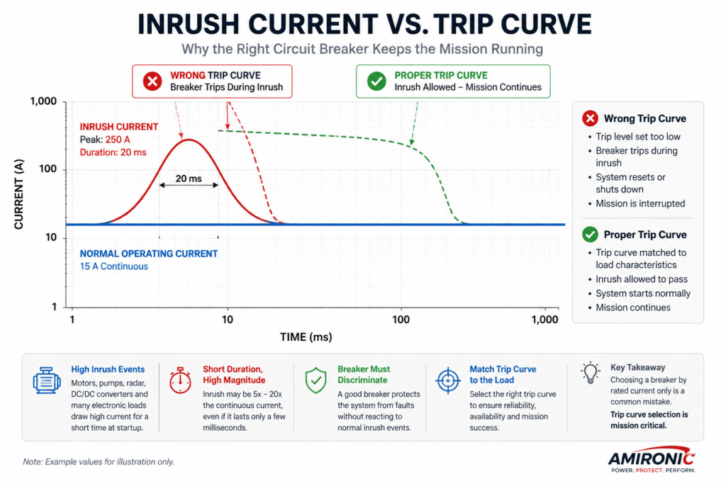
Many components, including motors, pumps, radar systems, mission computers, and power converters, draw a startup current that can be several times higher than their normal operating current. In most cases, this surge lasts only a few milliseconds. However, from the circuit breaker’s perspective, it is an event that must be handled correctly.

If the breaker’s trip curve is not matched to the load characteristics, it may interpret the inrush current as a fault condition and disconnect the circuit, even though the system is operating exactly as intended.

This is precisely why military circuit breaker selection goes far beyond choosing the appropriate current rating. Engineers must also understand how the load behaves during startup, how long the inrush current lasts, and which trip curve will allow the system to start normally while still providing reliable protection against genuine overloads and short circuits.

In other words, the best circuit breaker is not the one that trips first.

It is the one that can distinguish between normal operating conditions and a real electrical fault.

Figure 6: Inrush current can be several times higher than a system’s continuous operating current, even though it typically lasts only a few milliseconds. If the circuit breaker’s trip curve is not matched to the load characteristics, it may interpret a normal startup event as a fault and disconnect the circuit. A properly selected trip curve allows the system to start normally while still providing effective protection against genuine overloads and short circuits. The values shown in this illustration are for demonstration purposes only.

Myth vs. Reality – Selecting a Circuit Breaker for Military Systems

Myth Reality
“If a circuit breaker is rated at 100 A, it will work for any 100 A system.” The current rating is only the starting point. Engineers must also evaluate inrush current, trip curve, operating temperature, and installation conditions.
“All 100 A circuit breakers behave the same.” Two circuit breakers with the same current rating can respond very differently to the same load, depending on their trip curve and design characteristics.
“If the circuit breaker trips, there must be a short circuit.” In many cases, the trip is simply nuisance tripping caused by high inrush current or a normal dynamic load.
“Selecting the breaker based on the continuous current is enough.” The complete load profile must be considered, including continuous current, inrush current, startup duration, duty cycle, and environmental conditions.
“A circuit breaker is just a safety device.” In military platforms, the circuit breaker is an integral part of the power distribution architecture and has a direct impact on system reliability and operational availability.
“If the system resets, the problem is probably software.” Many system failures originate from an improperly selected circuit breaker whose characteristics do not match the load profile.

These mistakes are not theoretical. They occur in real-world programs and can lead to weeks of troubleshooting mission computers, radar systems, or software, only to discover that the root cause is a single component within the power distribution chain. That is why, in mission-critical platforms, circuit breaker selection is an engineering decision that directly affects the reliability and availability of the entire system, not just its protection against overloads and short circuits.

Case Study – When the Problem Is Not the Radar

Consider an EO/IR system installed on a stabilized turret that draws 18 A during normal continuous operation. All laboratory testing confirms that the system performs exactly as expected.

However, every time the turret begins to rotate, the system suddenly resets.

The initial investigation usually focuses on the usual suspects: software, the mission computer, electromagnetic interference (EMI), the power supply, or even the motor controller.

Engineers replace circuit boards, install new software versions, and spend hours collecting diagnostic data, yet the problem continues to appear intermittently.

Eventually, a detailed investigation reveals that the root cause is not the EO/IR system at all.

When the turret starts moving, the drive motors generate an inrush current of approximately 180 A for about 25 ms. From the system’s perspective, this is completely normal behavior. However, the circuit breaker’s trip curve is not matched to the startup characteristics of the load.

As a result, the breaker interprets the inrush current as a fault, briefly interrupts the power, and causes the mission computer or EO/IR system to reboot.

After replacing the breaker with a model whose trip curve is properly matched to the system’s startup profile, the problem disappears completely, without changing the radar, mission computer, software, or drive system.

This example illustrates how, in complex military platforms, what appears to be a software or hardware fault may actually originate from an improperly selected circuit protection device.

The values used in this example are for illustrative purposes only and do not represent any specific system.

Parameter Value
Continuous Load 18 A
Inrush Current 180 A
Inrush Duration 25 ms
Breaker Rating 20 A
Result ❌ Nuisance Trip
Correct Trip Curve ✅ Mission Continues

Conclusion

As military platforms become more advanced, their dependence on the underlying power distribution system continues to grow.

Radars, EO/IR systems, mission computers, electronic warfare equipment, and advanced communication systems all rely on a stable, protected, and reliable power supply. In many cases, the difference between a system that continues its mission and one that performs an unexpected reset is not the radar, the computer, or the software, but a single component that was selected during the design phase.

This is why selecting a circuit breaker involves far more than matching the current rating. Engineers must understand the complete electrical behavior of the system, including the load profile, inrush current, trip characteristics, environmental conditions, and the platform’s reliability requirements.

For decades, Airpax circuit breakers have been integrated into a wide range of military, aerospace, and naval platforms because of their ability to provide dependable circuit protection in some of the world’s most demanding operating environments. For system engineers, they are not simply protective devices, but an integral part of the platform’s power distribution architecture and overall reliability.

Ultimately, the success of a modern military platform is measured not only by how much power it can generate, but by how reliably it continues to operate when conditions become most demanding.

Because in mission-critical systems, even the smallest component can determine whether the mission succeeds or comes to an unexpected halt.

“In mission-critical platforms, a circuit breaker is far more than a protective device. It is one of the components that determines the survivability, reliability, and operational availability of the entire platform.”

🧩 Further Reading:
To place this comparison in a broader engineering context, it is recommended to review the earlier articles in this series. These provide deeper insight into the MIL-PRF-39019 specification, the behavior and importance of trip curves in hydraulic-magnetic circuit breakers, and the real-world challenges of power protection in rugged military and aerospace platforms.

  • MIL-PRF-39019 Circuit Breakers: Selection, Trip Curves, and Aerospace Power Protection
  • Why M39019 Is Not Just a Standard – It’s an Identity
  • Understanding Trip Curves in Hydraulic-Magnetic Circuit Breakers
  • Power Protection in Military Ground Platforms: Electrical Stability Under Vibration, Shock, and 28V Vehicle Systems
  • The Airpax AP Series: The Engineering Logic Behind a Hydraulic-Magnetic Circuit Breaker That Became a Military Standard
  • Hydraulic-Magnetic vs Thermal Circuit Breakers
  • Airpax IULN and IUGN Circuit Breakers: Sealed Hydraulic-Magnetic Protection for Rugged Electronic Systems
  • How Engineers Choose Between Airpax AP, IUL, IUG, and Commercial Circuit Breakers
  • SNAPAK Circuit Protectors: When Circuit Protection Becomes a User Interface
  • DIN Rail Circuit Breakers – Why Industrial Systems Demand More Than a Standard MCB
  • Why MIL-PRF-39019 Circuit Breakers Still Appear in New Defense Programs
  • Why a 10A Circuit Breaker Is Not Always Suitable for a 10A Load
  • Keeping Data Centers Running: The Role of Circuit Protection
  • Circuit Breaker or Control Device? Why Military Circuit Breakers Do More Than Protect
  • A 30mA Ground Fault Could Bring Down Thousands of GPUs – Designing Ground Fault Protection for Data Center CDUs
  • What Can We Learn from 40-Year-Old Hydraulic-Magnetic Circuit Breakers Still in Service?

Frequently Asked Questions (FAQ)

Is it enough to select a circuit breaker based only on the system’s current rating?

No. The current rating is only one of several selection criteria. Engineers should also consider inrush current, the trip curve, operating temperature, environmental conditions, interrupt rating, and the overall reliability requirements of the system.

What is inrush current?

Inrush current is a temporary surge of current, often several times higher than the normal operating current, that occurs when motors, power supplies, capacitors, transformers, or other electrical loads are energized. A circuit breaker that is not matched to the load characteristics may trip even though no fault exists.

What is a trip curve?

A trip curve defines how a circuit breaker responds to different current levels over time. Selecting the appropriate trip curve allows the system to tolerate normal startup currents while still providing reliable protection against overloads and short circuits.

Why do military platforms require specialized circuit breakers?

Military platforms operate under vibration, shock, extreme temperatures, voltage fluctuations, and rapidly changing electrical loads. Circuit breakers designed for general industrial applications may not provide the performance or long-term reliability required under these demanding conditions.

Do all circuit breakers with the same current rating behave the same way?

No. Two circuit breakers with the same current rating may have completely different trip curves, interrupt ratings, environmental capabilities, and operating characteristics. As a result, they can perform very differently under identical operating conditions.

Are hydraulic-magnetic circuit breakers affected by ambient temperature?

Hydraulic-magnetic circuit breakers are significantly less affected by ambient temperature than conventional thermal circuit breakers, providing more consistent trip characteristics across a wide range of operating conditions. However, the entire power distribution system must still be designed for the expected operating temperature.

Why are Airpax circuit breakers widely used in military applications?

Airpax circuit breakers have been used for decades in military, aerospace, and naval platforms because they offer a broad selection of trip curves, high reliability, and dependable performance in harsh operating environments.

Can a circuit breaker cause an electronic system to reset?

Yes. If the trip curve is not properly matched to the load characteristics, a normal inrush current can momentarily interrupt the power supply, causing a mission computer, EO/IR system, radar, or other electronic equipment to reset, even though no actual fault exists.


Glossary

Circuit Breaker

A protective device that automatically interrupts an electrical circuit during an overload or short circuit to protect equipment, wiring, and the power distribution system.

Trip Curve

A characteristic that defines how quickly a circuit breaker responds to different levels of current over time. The trip curve determines whether normal startup currents are tolerated or the circuit is interrupted.

Inrush Current

A temporary surge of current that occurs when motors, power supplies, capacitors, transformers, or other electrical loads are energized. It can be several times higher than the normal operating current but typically lasts only a few milliseconds.

Continuous Current

The steady-state current drawn by a system during normal operation.

Overcurrent

Any current that exceeds the intended operating current of a circuit. It may result from an overload or a short circuit and requires appropriate protection.

Short Circuit

A fault condition in which the electrical resistance of a circuit becomes very low, allowing excessive current to flow and potentially causing equipment damage unless interrupted quickly.

Interrupt Rating

The maximum fault current that a circuit breaker can safely interrupt without being damaged or creating a hazardous condition.

Hydraulic-Magnetic Circuit Breaker

A type of circuit breaker that uses a magnetic tripping mechanism with hydraulic time delay. This design provides more consistent performance over a wide temperature range than conventional thermal circuit breakers.

Nuisance Tripping

An unwanted circuit breaker trip that occurs even though no actual electrical fault exists, typically caused by normal inrush current or other temporary operating conditions.

Power Distribution

The system responsible for delivering electrical power from the source to all onboard equipment while providing switching, protection, and load management.

Power Bus

A primary electrical distribution line that supplies power to multiple systems or loads within the same platform.

Load Profile

The complete electrical behavior of a load over time, including continuous current, inrush current, peak demand, and duty cycle.

MIL-STD-1275

A U.S. military standard that defines the electrical power characteristics of military ground vehicles, including voltage transients, voltage drops, surges, and other electrical disturbances.

MIL-STD-810

A U.S. military environmental standard that specifies testing for shock, vibration, extreme temperatures, humidity, dust, and other environmental conditions.

Derating

The practice of reducing the allowable current or power rating of a component to account for actual operating conditions such as temperature, altitude, ventilation, or installation density.

Mission Availability

The ability of a system to remain fully operational and continue performing its intended mission without unexpected shutdowns or resets, even under demanding environmental and operational conditions.

Tags: Airpax

Related Articles

From 5kW to 100kW Racks – The Engineering Challenges Behind Modern AI Data Centers

27/05/2026amironicLTD

Circuit Breaker or Control Device? Why Military Circuit Breakers Do More Than Protect

02/07/2026amironicLTD

How Engineers Choose Between Airpax AP, IUL, IUG, and Commercial Circuit Breakers

18/03/2026amironicLTD

Recent Posts

  • Why Military Power Distribution Is Becoming the New Battlefield
  • High-Energy Laser Interception – The Engineering Behind Stable Line of Sight, Power Delivery, and Thermal Management
  • Why Do Counter-UAS Systems Lose Track of a Drone Right After Detecting It?
  • Why Programming a Rotary Position Sensor to 360° Is Sometimes the First Design Mistake
  • Don’t Design a New Footswitch – Build It from a Modular Platform

Categories

  • Air Switch
  • Circuit Breakers
  • Elapsed Time Indicator
  • Feedthrough
  • Footswitches
  • Gears & Transmission
  • Hour Meters
  • Infra Red Switches
  • INFRARED LAMPS
  • Low Noise Inertial MEMS
  • Mechanics
  • MEMS Gyroscope
  • MEMS Inertial
  • Microelectronics
  • Motors
  • Position Sensors
  • Power Supply
  • Pressure Sensors
  • Pressure Switch
  • Temperature Sensors
  • Tungsten and Molybdenum
  • Uncategorized
  • Vacuum Switches

Quick Contact

Fill out the form and our representatives will return to you

    Name (required)

    Email (required)

    Phone

    Message

    This site is protected by reCAPTCHA and the Google
    Privacy Policy and
    Terms of Service apply.

    Amironic Ltd.

    3 Rabinovich Street, Petah Tikva 4928144 , Israel. Tel: +972-3-9047744 E-mail: office@amironic.co.il
    Email
    Facebook
    Twitter
    LinkedIn
    YouTube
    Press on the ISO Certificate below for download
    ISO 9001:2015 Certification
    • MEMS Inertial
    • Circuit Breakers
    • Footswitches
    • Mechanical & Transmisions
    • Sensors
    • Motors
    • Electronics
    • Hand Control
    • Power Solutions

    News

    • Why Military Power Distribution Is Becoming the New Battlefield
    • High-Energy Laser Interception – The Engineering Behind Stable Line of Sight, Power Delivery, and Thermal Management
    • Why Do Counter-UAS Systems Lose Track of a Drone Right After Detecting It?
    • Why Programming a Rotary Position Sensor to 360° Is Sometimes the First Design Mistake
    • Don’t Design a New Footswitch – Build It from a Modular Platform
    About AmironicContactעברית
    © 2022 Amironic All rights reserved. All Trademarks are the property of their respective owners.
    • Increase Font
    • Decrease Font
    • Black & White
    • Inverse Colors
    • Highlight Links
    • Regular Font
    • Reset