flagעברית
flagEnglish
3 Rabinovich St., Petah-Tikva, Israel
+972 3 9047744
office@amironic.co.il
Facebook
Twitter
LinkedIn
YouTube
  • Products
    • MEMS Inertial
      • Gyros & Accels
      • IMU
      • Inertial Navigation
      • AHRS
    • Circuit Breakers
      • Airpax Circuit Breakers
      • Electronic Circuit Breakers
      • Aircraft Circuit Breakers
      • Thermal Circuit Breakers
      • Sealing Solutions & Guards
    • Footswitches
      • Pedals & Bellows
      • USB
      • Air Switches
      • Medical
      • Modular Bases System
      • Industrial
      • Foot Potentiometers
      • Wireless
    • Mechanical & Transmisions
      • Gears
      • Sealing Solutions
      • Gearboxes
      • Couplings
      • Shafts & Bearings
      • Fasteners
      • Mechanical & Springs
      • Linear Motion
      • Anti-Vibration
    • Sensors
      • Thermostats
      • Temperature
      • Position
      • Pressure
      • Speed
      • Level Sensor
      • Load Cells
      • Flex Sensors
      • Membrane Potentiometer
    • Motors
      • Geared DC
      • Brushless DC
      • Step Motors with Gearbox
      • Torque Motors & Brushless Servo
      • DC Motors
    • Electronics
      • Xenon & IR Lamps
      • Counters & Meters
      • Microelectronics Packaging
      • Waterproof Switches
      • Micro Switches
    • Hand Control
      • Operator Controls (JOYSTICK)
      • Electrical
      • Pneumatic (Medical)
      • USB Hand Control
      • Air Push Button
      • Pressure Switch
      • IR Switch
    • Power Solutions
      • Rugged & Military Power Supply
      • Input Power Protection
      • Sealed Military Power Adaptor
      • Triple Output Military Power Supply Series – up to 250 W
    • Materials
      • Molybdenum and Advanced Alloys (TZM, MOLA, HCT)
      • Tungsten (Wolfram) and Advanced Alloys – High-Performance Materials for Extreme Conditions
      • Materials for Gears
  • Shop
  • Companies
  • About Amironic
  • News
  • Contact
Product was added to your cart

Cart

waze

The Antenna Hasn’t Moved – So Why Did We Lose the Link? The Role of the IMU in Antenna Positioning Systems

MEMS Inertial09/08/2026amironicLTD

In communication systems based on directional antennas, antenna pointing accuracy is a critical factor in maintaining link quality.

When an antenna is pointed toward a satellite, UAV, ground station, or another remote platform, even a small angular deviation can reduce signal strength, degrade data throughput, and in some cases cause the link to be lost entirely.

But this raises an interesting problem:

What happens when the Antenna Positioning system reports that the antenna is exactly at the correct angle – yet the link becomes weaker or disappears?

The answer may be simple:

The antenna has not moved relative to its base – but the base itself has moved.

A Position Sensor Knows Where the Antenna Is – Not Necessarily Where It Is Pointing

A typical Antenna Positioning system uses Azimuth and Elevation mechanisms to point the antenna toward the required direction.

To determine the actual position of each axis, the system may use an Encoder, Resolver, Hall Effect Sensor, or another Position Feedback technology.

For example, the controller may command:

Azimuth = 70°

Elevation = 25°

The sensors can then confirm that both axes have reached the commanded positions.

If the system is installed on a fixed, stationary base, this information may be sufficient to maintain the required pointing direction.

But the situation changes completely when the antenna is installed on a moving platform.

For example:

  • An off-road vehicle
  • A vessel rolling with the waves
  • An airborne platform changing Pitch, Roll, or Yaw
  • A mobile system that rotates or changes its orientation

In these situations, the Position Sensor may still report that the antenna is exactly at the commanded angle relative to its base.

But relative to the external reference frame, the Line of Sight has already changed.

A Simple Example

Consider an antenna installed on a vehicle and accurately pointed toward a remote communication station.

The Azimuth mechanism is at the correct angle, and the Encoder reports no position error.

Now the vehicle rotates several degrees to the right.

From the Encoder’s perspective:

Nothing has changed.

The antenna is still at exactly the same angle relative to the vehicle.

But from the perspective of the remote communication station:

The antenna is no longer pointing in the same direction.

This is exactly why Position Feedback alone is not always sufficient in dynamic Antenna Positioning systems.

The system needs to know not only:

Where is the antenna?

but also:

How is the platform moving?

And this is where the IMU comes into the picture.
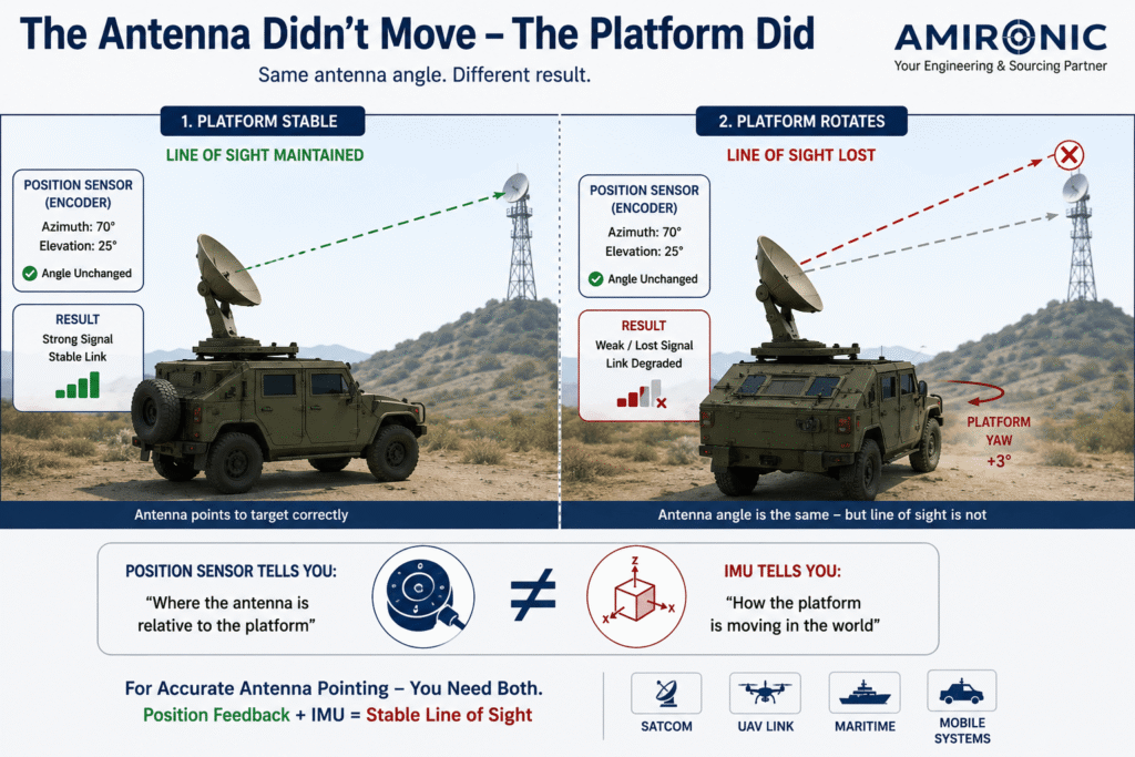
Figure 1: An antenna can remain at the same angle relative to the platform while losing its Line of Sight as the platform itself changes orientation. Combining Position Feedback with an IMU allows the system to determine both the antenna position and the platform motion, helping maintain accurate pointing toward the target.

This Is Where the IMU Comes Into the Picture

An IMU – Inertial Measurement Unit – measures platform motion using gyroscopes and accelerometers across multiple axes.

In an Antenna Positioning system, this information allows the controller to determine whether a change in the antenna’s orientation relative to the external reference frame is caused by movement of the antenna mechanism itself or by motion of the platform on which it is mounted.

For example, if a vessel rolls by 2° due to a wave, the Position Feedback system may continue to report that the antenna is exactly at the commanded Elevation angle.

The IMU, however, detects the change in the platform’s Roll.

The control system can use this information to command the Antenna Positioning mechanism in the opposite direction and compensate for the platform motion.

The objective is simple:

Platform moves → IMU detects motion → Controller calculates correction → Antenna compensates

This makes it possible to maintain a stable Line of Sight even when the base supporting the antenna is moving.

Why Is Response Time Just as Important as Accuracy?

In a static system, the primary concern may be how accurately the angle is measured.

In a mobile system, another parameter enters the equation: time.

Assume the platform is rotating at a rate of 30° per second.

If the complete measurement and control chain responds with a delay of 10 milliseconds, the platform will already have moved:

30°/s × 0.010s = 0.3°

This means that even if the sensors themselves are highly accurate, Latency within the system can create a significant Pointing Error.

And the narrower the antenna Beamwidth, the more significant that same angular error becomes.

Therefore, when selecting an IMU for an Antenna Positioning system, it is not enough to consider a single specification such as Gyro Bias.

The complete dynamic system should be evaluated, including:

  • Data Rate
  • Bandwidth
  • Latency
  • Angular Rate Range
  • Noise
  • Bias Stability
  • Alignment Accuracy
  • Performance across the required temperature range

A Narrow Beamwidth Turns a Small Error Into a Big Problem

A directional antenna concentrates its energy into a defined beam.

As the beam becomes narrower, higher Gain and a more focused communication link can be achieved. At the same time, however, the system becomes more sensitive to Pointing Error.

Consider a simple example.

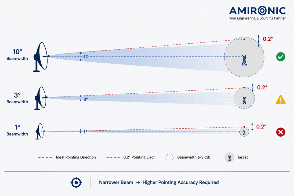
If an antenna has a Beamwidth of 10°, a Pointing Error of 0.2° may be relatively small compared with the overall beam width.

But if the antenna has a Beamwidth of only 1°, the same 0.2° error already represents a significant portion of the beam.

This is why there is no single “IMU Accuracy” specification that is suitable for every Antenna Positioning system.

The IMU requirements should also be derived from the antenna characteristics, Beamwidth, platform dynamics, and the overall accuracy required from the Control Loop.

In other words:

The narrower the Beam, the more critical the quality of the inertial data and the response speed of the system become.

Figure 2: The narrower the antenna Beamwidth, the more sensitive the system becomes to Pointing Error. The same angular error of 0.2° may be almost negligible with a wide beam, but highly significant with a narrow-beam antenna.

Not Every IMU Is Suitable for Antenna Positioning

Once we understand that the IMU is part of the antenna control loop, it becomes clear that selecting a unit based on a single accuracy specification is not enough.

An Antenna Positioning system is dynamic. It must measure motion, transfer the data to the controller, calculate the required correction, and move the antenna – all fast enough to apply the correction before platform motion develops into a significant Pointing Error.

Several parameters therefore need to be evaluated together.

Gyro Bias

Gyro Bias is the error a gyroscope may indicate even when no actual motion is present.

In a system that must maintain its pointing direction over time, Bias can accumulate and cause the system to interpret rotation even when the platform is actually stationary.

The higher the required Pointing Accuracy, the more important Bias Stability becomes.

Angular Random Walk – ARW

Even with low Bias, the measurement is not completely free of noise.

Angular Random Walk describes one of the gyroscope’s noise characteristics over time. In an Antenna Positioning system, measurement noise can enter the control loop and cause small, unnecessary corrections by the positioning mechanism.

Therefore, accuracy alone is not enough – the measurement must also be sufficiently stable and low-noise for the control algorithm.

Bandwidth and Data Rate

These are two parameters that are easy to confuse.

Data Rate describes how frequently the IMU can provide new data to the system.

Bandwidth describes how quickly the sensor can meaningfully track actual changes in motion.

An IMU may provide thousands of samples per second, but if its Bandwidth is too low relative to the platform dynamics, a high sampling rate alone will not solve the problem.

On platforms subject to rapid motion, vibration, or sudden changes in orientation, both parameters are important.

Latency – The Specification That Is Easy to Overlook

Latency is the time between the occurrence of motion and the moment the corresponding measurement data becomes available to the control system.

In a static system, a few milliseconds may seem insignificant.

In a dynamic system, they can translate directly into Pointing Error.

If the platform is rotating at 60° per second and the measurement data arrives with a delay of 5 ms:

60°/s × 0.005s = 0.3°

This means that even before considering Encoder Accuracy, Backlash, installation errors, or motor response time, a potential error of 0.3° has already been introduced by the delay alone.

For an antenna with a wide Beamwidth, the effect may be limited.

For a Narrow-Beam Antenna, however, this can already represent a significant error.

What About Temperature?

Many Antenna Positioning systems do not operate under laboratory conditions.

They may be installed on vessels, ground vehicles, airborne platforms, or outdoor systems exposed to changing temperatures throughout their operating cycle.

MEMS Gyroscopes and Accelerometers are affected by temperature.

Therefore, when evaluating an IMU for such an application, it is important to consider not only its performance at room temperature, but also how the unit is calibrated and how it performs across the entire required temperature range.

A high-performance IMU is more than just a collection of MEMS sensors.

A significant part of its performance comes from calibration, temperature compensation, signal processing, and its ability to provide consistent data under changing environmental conditions.

The IMU Is Only One Part of the Pointing Error Budget

It is also important not to assign the entire responsibility for system accuracy to the IMU.

The total Pointing Error can be influenced by several sources:

IMU Error + Position Sensor Error + Mechanical Backlash + Alignment Error + Control Latency + Structural Flexibility

For example, there is little benefit in using an extremely accurate IMU if significant Backlash exists in the Azimuth mechanism.

Likewise, an exceptionally accurate Encoder will not solve a high-Latency problem in the control system.

The correct approach to designing an Antenna Positioning system is therefore to first define the required Pointing Accuracy at the system level, and only then allocate the Error Budget among the sensors, mechanics, electronics, and control algorithm.

The goal is not to select the IMU with the most impressive number on the datasheet.

The goal is to select an IMU that matches the dynamics and the Pointing Error Budget of the complete system.

Figure 3: The total Pointing Error is influenced by a combination of factors, including IMU accuracy, Position Sensor accuracy, Mechanical Backlash, Alignment Error, and Latency. Therefore, the Error Budget of the entire system should be evaluated rather than focusing on a single component.

How Does the IMU Integrate Into the Antenna Control Loop?

In a dynamic Antenna Positioning system, the IMU does not replace the Encoder or Position Sensor.

Each serves a different purpose.

The Position Sensor measures the actual angular position of the Azimuth and Elevation axes relative to the antenna mechanism.

The IMU measures the motion of the platform on which the system is installed.

The control system combines these two sources of information to calculate how the antenna should move in order to maintain the required pointing direction.

In simplified form, the control loop can be described as:

IMU → Platform Motion

Position Sensor → Antenna Position

Controller → Pointing Correction

Motor / Actuator → Antenna Movement

This process is repeated continuously.

When the platform begins to rotate, the IMU detects the change. The controller calculates the required correction and commands the antenna mechanism to move accordingly.

The objective is for the antenna motion to compensate for platform motion before a significant deviation develops in the Line of Sight.

Feedforward and Feedback – Why Use Both?

The stabilization system can be viewed as a combination of two types of information.

Position Feedback allows the controller to determine what actually happened: Did the antenna mechanism reach the commanded angle?

Data from the IMU can enable a rapid response to platform motion before the resulting Pointing Error develops into a significant deviation in antenna direction.

For example, if a vehicle begins turning to the left, there is no need to wait until the system detects that the antenna has already deviated significantly from the required Line of Sight.

The IMU detects the platform’s angular rate, allowing the controller to begin compensating through the Azimuth mechanism.

At the same time, the Position Sensor closes the loop by confirming that the mechanism actually performed the commanded movement.

The two measurements therefore complement each other:

IMU – What is the platform doing?

Position Feedback – What did the antenna actually do?

Why Can a Tactical-Grade IMU Be Relevant?

Not every Antenna Positioning system requires a Tactical-Grade IMU.

For an antenna with a wide Beamwidth, installed on a slowly moving platform and used in an application where a brief interruption in the link is not critical, a simpler solution may be sufficient.

The requirements change when the antenna is more directional, the platform is more dynamic, or the system must maintain a stable Line of Sight during motion, vibration, and temperature changes.

In these applications, parameters such as the following become increasingly important:

  • Gyro Bias Stability
  • Angular Random Walk
  • Low Noise
  • High Bandwidth
  • High Data Rate
  • Low Latency
  • Temperature Compensation
  • Shock and Vibration Performance

This is where the difference between a basic MEMS Sensor and an IMU designed for accurate, dynamic applications becomes significant.

Gladiator Technologies in Antenna Positioning Systems

Gladiator Technologies MEMS IMUs are designed for applications requiring accurate motion measurement, high data rates, low Latency, and stable performance under changing environmental conditions.

In an Antenna Positioning system, the IMU can provide the controller with the inertial motion data required to compensate for the platform’s Roll, Pitch, and Yaw.

However, it is important to emphasize that selecting the appropriate model should not begin with the question, “Which IMU is the most accurate?”

It should begin with the system requirements:

What is the antenna Beamwidth?

What is the allowable Pointing Error?

How fast can the platform move?

What Bandwidth is required by the control loop?

What is the maximum acceptable Latency?

Under what temperature, vibration, and shock conditions must the system operate?

Only after these requirements have been defined can the appropriate IMU performance level be selected and evaluated as part of the overall Antenna Positioning system Error Budget.

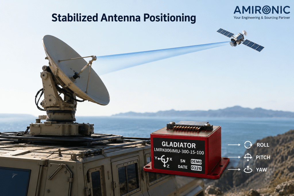
Figure 4: Antenna stabilization on a mobile platform – the IMU measures the platform’s Roll, Pitch, and Yaw motion in real time and provides the control system with the data required to compensate for that motion, maintain accurate antenna pointing, and preserve a stable communication link.

In Which Antenna Positioning Systems Is This Combination Particularly Important?

The need for inertial stabilization is not limited to a specific type of antenna or platform.

The same principle applies to any system in which a directional antenna must maintain a communication link while the platform supporting it is in motion.

SATCOM on Mobile Platforms

In Satellite Communication systems, the antenna must continue pointing toward the satellite even as the platform changes its orientation.

On a vessel, for example, Roll and Pitch change continuously due to wave motion. On a ground vehicle, changes in slope, turns, and vehicle body motion can alter the antenna’s orientation relative to the satellite.

The stabilization system must therefore make continuous corrections to keep the satellite within the antenna beam.

Communication Between Moving Platforms

The challenge becomes even more complex when not only the antenna platform is moving, but the other end of the link is moving as well.

For example, in a directional communication link between a ground platform and a UAV, the Antenna Positioning system must simultaneously compensate for motion of the platform on which it is installed and track changes in the position of the remote platform.

In this case, the system is not simply stabilizing an antenna.

It must also track a moving target and keep it within the Beam.

Maritime Systems

The maritime environment is a particularly good example of why stabilization matters.

Even when a vessel is traveling on a constant heading, the antenna may experience almost continuous Roll, Pitch, and Yaw motion.

With a narrow-Beamwidth antenna, even relatively small vessel movements can result in significant changes in beam direction.

The control system must therefore be capable of detecting this motion quickly and continuously compensating for it.

Antenna Positioning on Airborne Platforms

Airborne platforms introduce additional challenges, including rapid changes in orientation, vibration, acceleration, and a wide range of operating temperatures.

In these applications, the question is not only how accurate the IMU is under static conditions, but also how it performs during rapid motion and how its data integrates into the control loop.

Do You Always Need a Tactical-Grade IMU?

No.

And this is an important consideration when designing the system.

Selecting an IMU with performance far beyond what the application requires can increase cost and complexity without significantly improving overall system performance.

On the other hand, an IMU that cannot meet the dynamic requirements of the application may itself become a significant contributor to the Pointing Error Budget.

The selection process should therefore begin with the application requirements.

Questions to consider include:

  • What is the antenna Beamwidth?
  • What Pointing Accuracy is required?
  • What are the maximum Roll, Pitch, and Yaw rates?
  • What motion and vibration frequencies must be measured?
  • What is the maximum Latency the control system can tolerate?
  • How long must the system maintain its pointing direction?
  • Over what temperature range must the system operate?

Only after answering these questions should the required Bias, ARW, Bandwidth, Data Rate, and other IMU performance parameters be defined.

Example: The Same Antenna on Two Different Platforms

Consider the same antenna installed in two different applications.

In the first application, it is mounted on an almost stationary ground-based system that experiences only slow changes in orientation.

In the second, the same antenna is installed on a small vessel operating at sea.

The antenna has not changed.

The communication link requirements may even be identical.

But the requirements placed on the stabilization system are completely different.

In the ground-based system, the rate of change is relatively low, allowing corrections to be made at a more moderate rate.

On the vessel, however, the IMU and control system must cope with continuous motion across multiple axes.

This is why selecting an IMU based on the statement:

“We need an accurate IMU”

is not a sufficient engineering requirement.

A better question is:

“What platform motion must the antenna compensate for, and how much Pointing Error can the link tolerate?”

The answer to that question begins to define the IMU the system actually needs.

Figure 5: On a maritime platform, Roll, Pitch, and Yaw continuously change the antenna’s orientation relative to the target. The IMU measures the platform motion and enables the control system to compensate for it in real time, helping maintain a stable communication link.

Case Study: An Autonomous UAV Maintaining a SATCOM Link During a Maneuver

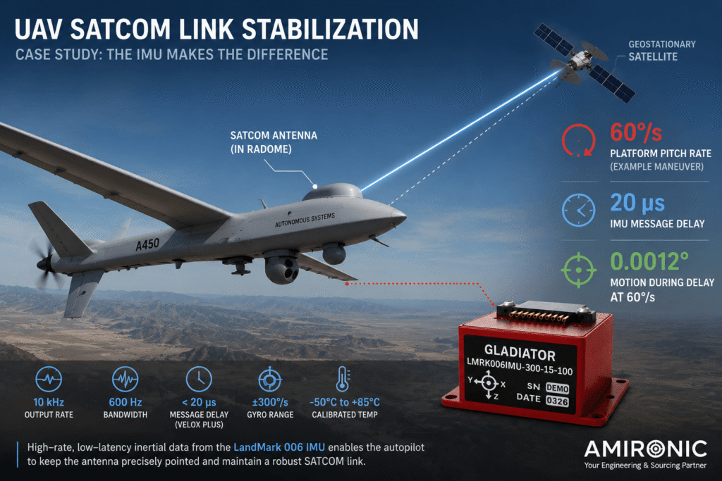
Consider an autonomous UAV equipped with a directional antenna for satellite communications. After Satellite Acquisition, the Antenna Positioning system must keep the center of the antenna beam pointed toward the satellite even while the UAV is maneuvering.

For this example, assume:

  • Antenna Beamwidth: 2°
  • Pitch rate during the maneuver: 60°/s
  • Required Pointing Error: less than 0.1°
  • IMU: Gladiator Technologies LandMark 006 with VELOX Plus

The LandMark 006 with VELOX Plus offers, among other specifications, an output rate of up to 10 kHz, Bandwidth of up to 600 Hz, and a Digital Message Delay of 20 µs. The gyroscope range is ±300°/s.

What Happens During the Maneuver?

Assume the UAV changes Pitch at a rate of:

60°/s

In just 100 ms, its orientation has already changed by:

60 × 0.1 = 6°

That is three times the 2° Beamwidth in our example.

In other words, without compensation, the fact that the antenna itself has not changed its angle relative to the UAV body does not help. Its Line of Sight relative to the satellite is changing rapidly.

Now Let’s Look at Latency

With VELOX Plus, the specified Digital Message Delay is 20 µs.

At an angular rate of 60°/s, the platform motion occurring during 20 µs is:

60°/s × 0.000020s = 0.0012°

This means that the theoretical contribution associated with the IMU message delay alone is approximately:

0.0012°

By comparison, if another measurement system introduced a Latency of 5 ms:

60°/s × 0.005s = 0.3°

And at 10 ms:

60°/s × 0.010s = 0.6°

Relative to a Beamwidth of 2°, the difference is already significant.

Message Delay Pointing Change at 60°/s
20 µs 0.0012°
1 ms 0.06°
5 ms 0.30°
10 ms 0.60°

It is important to note that this calculation refers only to the angular motion occurring during the delay. It does not mean that the total system Pointing Accuracy is 0.0012°. Controller and motor Latency, Encoder Error, Alignment Error, Backlash, Structural Flexibility, and other error sources must still be considered.

What About Alignment?

The LandMark 006 specification lists a typical Gyro Alignment of 500 µrad.

500 µrad is approximately:

0.0286°

If our system requires a total Pointing Error of less than 0.1°, it becomes clear why Alignment and installation calibration need to be included in the overall Error Budget rather than treated as a mechanical detail to be addressed at the end of the design process.

What Happens Under Real Flight Conditions?

A UAV does not operate on a laboratory bench. It is exposed to vibration, temperature changes, and acceleration.

The LandMark 006 is specified for 8 gRMS vibration from 50 Hz to 2 kHz, an operational Shock of 1000g, and a calibrated temperature range of -50°C to +85°C.

The unit is also relatively small and lightweight, at approximately 17 grams and about 25.4 × 25.4 × 15.8 mm. These characteristics can be particularly important for airborne platforms where SWaP – Size, Weight and Power – is part of the system requirements.

Engineering Conclusion

In a system like this, the challenge is not simply to “find the satellite.”

The real challenge is to keep pointing toward it while the UAV itself is changing orientation.

As the Beamwidth becomes narrower and the platform becomes more dynamic, parameters such as Latency, Bandwidth, Alignment, Noise, and Bias Stability become directly relevant to the system’s ability to maintain the communication link.

This is why selecting an IMU for Antenna Positioning should begin with the platform dynamics and the system-level Pointing Error Budget, rather than with a single accuracy specification on the datasheet.

Conclusion

In an Antenna Positioning system, the fact that the antenna is at the correct angle relative to its positioning mechanism does not necessarily mean that it is still pointing toward the target.

When the antenna is installed on a ground vehicle, vessel, UAV, or airborne platform, any change in the platform’s Roll, Pitch, or Yaw also affects the antenna’s Line of Sight. Position Feedback tells the system where the antenna axes are, while the IMU provides the missing information about the motion of the platform itself.

The narrower the Beamwidth and the more dynamic the platform, the more important parameters such as Bias Stability, ARW, Bandwidth, Data Rate, Alignment, and Latency become.

As we saw in the Case Study, at an angular rate of 60°/s, a delay of 5 ms corresponds to 0.3° of angular motion. By comparison, a Message Delay of 20 µs corresponds to just 0.0012°. This does not represent the total system Pointing Error, but it clearly illustrates why Latency should be considered as part of the stabilization loop design rather than simply another specification on a datasheet.

The Gladiator Technologies LandMark 006 IMU with VELOX Plus offers a Data Rate of up to 10 kHz, Bandwidth of up to 600 Hz, and a Digital Message Delay of 20 µs, along with a typical Gyro Bias Stability of 0.8°/h and an ARW of 0.0254°/√Hr.

But selecting an IMU for an Antenna Positioning system does not begin with the question:

“Which IMU is the most accurate?”

It begins with different questions:

How much does the platform move?
How narrow is the Beam?
What is the allowable Pointing Error?
How quickly must the system respond?

Once these requirements are properly defined, engineers can build a Pointing Error Budget and select the IMU, Position Sensor, positioning mechanism, and Control Loop that best match the requirements of the complete system.

Because ultimately, the challenge is not simply to point the antenna toward the target – it is to keep it pointed at the target while the platform beneath it continues to move.

🧩 Further Reading and Deeper Insight

This article is part of a broader series exploring the engineering principles behind modern inertial sensing and motion stability in advanced control and navigation systems. For deeper technical context and system-level insights, you may also find the following articles valuable:

  • Bridging Control and Navigation: How Advanced MEMS IMUs Are Redefining System Performance
  • Gyro and IMU for Advanced Control Systems
  • The Silent Problem of Precision Systems – Why Gyros and IMUs Are Control Components, Not Just Sensors
  • Why External Sync is Critical in Gyro and IMU Systems
  • Stabilization, Tracking & Time Sync: The Foundation of Precise Line-of-Sight Control
  • Mission-Grade Stabilization in Dynamic EO/IR Systems: Why Bandwidth, Data Rate, and Phase Lag Define Gimbal Performance
  • Why Gladiator? What Truly Differentiates a High-End MEMS IMU Manufacturer
  • Common Misconceptions About MEMS Inertial Sensors
  • Bias Stability vs. Bias Instability: What really determines the performance of Gyro and IMU systems in stabilization, tracking, and navigation
  • Scale Factor in MEMS IMUs – The Error That Quietly Destroys Accuracy
  • The IMU Was Excellent. The Image Still Shook.
  • 2000Hz IMU? Before You Get Impressed, Understand Three Completely Different Numbers
  • SX3: Pushing MEMS Beyond Traditional Stabilization
  • Why a Smaller IMU Can Save Months of Development
  • Your Image Still Shakes Despite Choosing a Gyroscope with Excellent Bias Stability
  • Why Replacing an IMU Can Lead to Weeks of Recalibration
  • From IMU to INS: How a Tactical Navigation System Is Really Built
  • When GPS Is Lost, It’s Already Too Late to Choose an IMU
  • Why Do Counter-UAS Systems Lose Track of a Drone Right After Detecting It?
  • When GPS Lies: Why IMUs Are Becoming Mission-Critical in the Era of Autonomous Wingmen
  • How Does a MEMS Sensor Become a Tactical-Grade IMU?

Frequently Asked Questions (FAQ)

What is the difference between an IMU and a Position Sensor in an Antenna Positioning system?

A Position Sensor or Encoder measures the position of the antenna axes relative to the mechanism on which the antenna is mounted. An IMU measures the inertial motion of the platform itself, including Roll, Pitch, and Yaw. Combining information from both allows the controller to compensate for platform motion and maintain the required antenna pointing direction.

Can an antenna be stabilized using only an Encoder?

In a system mounted on a fixed base, sometimes yes. On a mobile platform, however, an Encoder alone does not know that the vehicle, vessel, or UAV has changed its orientation. Dynamic systems may therefore also require inertial motion data.

Why is Beamwidth important when selecting an IMU?

The narrower the Beamwidth, the more sensitive the antenna becomes to Pointing Error. A small angular error that may be negligible with a wide-beam antenna can become significant with a highly directional narrow-beam antenna.

Why is Latency important in an Antenna Positioning system?

The platform continues moving during the time between the actual motion and the availability of the measurement data. For example, at an angular rate of 60°/s, a delay of 5 ms corresponds to 0.3° of angular motion. Latency is therefore an important part of the Pointing Error Budget in dynamic systems.

Does a high Data Rate necessarily mean that an IMU is suitable for antenna stabilization?

No. Data Rate is only one parameter. Bandwidth, Latency, Bias Stability, Noise, Alignment, measurement range, and performance across the required temperature range should also be considered.

Does every Antenna Positioning system require a Tactical-Grade IMU?

No. The requirement depends on the antenna Beamwidth, platform dynamics, required Pointing Accuracy, and environmental conditions. A nearly stationary system with a wide Beam may be adequately served by a simpler solution, while a dynamic platform with a Narrow Beam may impose significantly more demanding requirements.

What is a Pointing Error Budget?

A Pointing Error Budget breaks down the total allowable pointing error among the different sources that contribute to it, such as the IMU, Position Sensor, Alignment, Mechanical Backlash, Latency, and structural effects. The objective is to ensure that the combined errors remain within the system’s overall Pointing Accuracy requirement.

What specifications does the LandMark 006 offer for dynamic applications?

The LandMark 006 with VELOX Plus offers a Data Rate of up to 10 kHz, Bandwidth of up to 600 Hz, and a Digital Message Delay of 20 µs. The gyroscope range is ±300°/s, and the unit is calibrated over a temperature range of -50°C to +85°C.

Can an IMU alone maintain a SATCOM link?

No. The IMU provides information about platform motion, but link stabilization depends on the complete system, including the Antenna Positioning Mechanism, Position Feedback, Controller, Motors/Actuators, and the control algorithm.

Key Terms

Antenna Positioning – A mechanical and electronic system responsible for positioning an antenna in Azimuth and Elevation and maintaining the required pointing direction.

IMU – Inertial Measurement Unit – An inertial sensing unit that typically combines gyroscopes and accelerometers to measure motion and acceleration along multiple axes.

Position Feedback – Information provided by an Encoder, Resolver, or other Position Sensor that allows the controller to determine the actual angular position of the antenna mechanism.

Azimuth – The horizontal angle describing the antenna’s direction around the vertical axis.

Elevation – The vertical angle of the antenna relative to the horizontal plane.

Roll, Pitch, Yaw – The three rotational axes of a platform. Motion around any of these axes can change the antenna’s orientation relative to the target.

Line of Sight – LOS – The direct pointing line between the antenna and its target, such as a satellite, ground station, or another platform.

Beamwidth – The angular width of the antenna beam. In general, the narrower the beam, the greater the required Pointing Accuracy.

Pointing Error – The angular difference between the antenna’s desired pointing direction and its actual pointing direction.

Pointing Error Budget – The allocation of the allowable pointing error among different error sources in the system, such as the IMU, Position Sensor, Alignment, Backlash, and Latency.

Gyro Bias Stability – A measure of the stability of the gyroscope’s Bias over time. The LandMark 006 specifies a typical value of 0.8°/h.

ARW – Angular Random Walk – A parameter describing a component of gyroscope noise that contributes to angular uncertainty over time. The LandMark 006 specifies a typical ARW of 0.0254°/√Hr.

Bandwidth – The frequency range over which the IMU can effectively track changes in motion. The LandMark 006 with VELOX Plus specifies a maximum Bandwidth of 600 Hz.

Data Rate / Output Rate – The rate at which the IMU provides new measurements to the control system. VELOX Plus supports up to 10 kHz.

Latency / Message Delay – The time before measurement data becomes available to the system. In a dynamic application, this delay can translate directly into Pointing Error. VELOX Plus specifies a Digital Message Delay of 20 µs.

Alignment Error – An error caused by misalignment between the IMU measurement axes and the coordinate axes of the platform or antenna system.

Mechanical Backlash – Mechanical play within a transmission or positioning mechanism that can prevent a small command change from immediately producing the corresponding precise change in antenna angle.

SATCOM – Satellite Communication – Communication via satellite. When the antenna is installed on a mobile platform, the stabilization system must maintain pointing toward the satellite despite platform motion.

Tags: Gladiator_Technologies

Related Articles

High Speed LandMark 60 IMU

03/10/2018amironicLTD

The IMU Was Excellent. The Image Still Shook.

01/06/2026amironicLTD

SX3: Pushing MEMS Beyond Traditional Stabilization

24/06/2026amironicLTD

Recent Posts

  • Why Every Battery Pack Needs a Temperature Sensor – Not Just Electric Vehicles
  • Why a Dirty Lens Is More Than Just an Optical Problem – It’s an Engineering Challenge in Endoscopy Systems
  • The Antenna Hasn’t Moved – So Why Did We Lose the Link? The Role of the IMU in Antenna Positioning Systems
  • Why a Standard Thermal Circuit Breaker Isn’t Always the Right Choice for Data Centers
  • How Does a MEMS Sensor Become a Tactical-Grade IMU?

Categories

  • Air Switch
  • Circuit Breakers
  • Elapsed Time Indicator
  • Feedthrough
  • Footswitches
  • Gears & Transmission
  • Hour Meters
  • Infra Red Switches
  • INFRARED LAMPS
  • Low Noise Inertial MEMS
  • Mechanics
  • MEMS Gyroscope
  • MEMS Inertial
  • Microelectronics
  • Motors
  • Position Sensors
  • Power Supply
  • Pressure Sensors
  • Pressure Switch
  • Temperature Sensors
  • Tungsten and Molybdenum
  • Uncategorized
  • Vacuum Switches

Quick Contact

Fill out the form and our representatives will return to you

    Name (required)

    Email (required)

    Phone

    Message

    This site is protected by reCAPTCHA and the Google
    Privacy Policy and
    Terms of Service apply.

    Amironic Ltd.

    3 Rabinovich Street, Petah Tikva 4928144 , Israel. Tel: +972-3-9047744 E-mail: office@amironic.co.il
    Email
    Facebook
    Twitter
    LinkedIn
    YouTube
    Press on the ISO Certificate below for download
    ISO 9001:2015 Certification
    • MEMS Inertial
    • Circuit Breakers
    • Footswitches
    • Mechanical & Transmisions
    • Sensors
    • Motors
    • Electronics
    • Hand Control
    • Power Solutions

    News

    • Why Every Battery Pack Needs a Temperature Sensor – Not Just Electric Vehicles
    • Why a Dirty Lens Is More Than Just an Optical Problem – It’s an Engineering Challenge in Endoscopy Systems
    • The Antenna Hasn’t Moved – So Why Did We Lose the Link? The Role of the IMU in Antenna Positioning Systems
    • Why a Standard Thermal Circuit Breaker Isn’t Always the Right Choice for Data Centers
    • How Does a MEMS Sensor Become a Tactical-Grade IMU?
    About AmironicContactעברית
    © 2022 Amironic All rights reserved. All Trademarks are the property of their respective owners.
    • Increase Font
    • Decrease Font
    • Black & White
    • Inverse Colors
    • Highlight Links
    • Regular Font
    • Reset