flagעברית
flagEnglish
3 Rabinovich St., Petah-Tikva, Israel
+972 3 9047744
office@amironic.co.il
Facebook
Twitter
LinkedIn
YouTube
  • Products
    • MEMS Inertial
      • Gyros & Accels
      • IMU
      • Inertial Navigation
      • AHRS
    • Circuit Breakers
      • Airpax Circuit Breakers
      • Electronic Circuit Breakers
      • Aircraft Circuit Breakers
      • Thermal Circuit Breakers
      • Sealing Solutions & Guards
    • Footswitches
      • Pedals & Bellows
      • USB
      • Air Switches
      • Medical
      • Modular Bases System
      • Industrial
      • Foot Potentiometers
      • Wireless
    • Mechanical & Transmisions
      • Gears
      • Sealing Solutions
      • Gearboxes
      • Couplings
      • Shafts & Bearings
      • Fasteners
      • Mechanical & Springs
      • Linear Motion
      • Anti-Vibration
    • Sensors
      • Thermostats
      • Temperature
      • Position
      • Pressure
      • Speed
      • Level Sensor
      • Load Cells
      • Flex Sensors
      • Membrane Potentiometer
    • Motors
      • Geared DC
      • Brushless DC
      • Step Motors with Gearbox
      • Torque Motors & Brushless Servo
      • DC Motors
    • Electronics
      • Xenon & IR Lamps
      • Counters & Meters
      • Microelectronics Packaging
      • Waterproof Switches
      • Micro Switches
    • Hand Control
      • Operator Controls (JOYSTICK)
      • Electrical
      • Pneumatic (Medical)
      • USB Hand Control
      • Air Push Button
      • Pressure Switch
      • IR Switch
    • Power Solutions
      • Rugged & Military Power Supply
      • Input Power Protection
      • Sealed Military Power Adaptor
      • Triple Output Military Power Supply Series – up to 250 W
    • Materials
      • Molybdenum and Advanced Alloys (TZM, MOLA, HCT)
      • Tungsten (Wolfram) and Advanced Alloys – High-Performance Materials for Extreme Conditions
      • Materials for Gears
  • Shop
  • Companies
  • About Amironic
  • News
  • Contact
Product was added to your cart

Cart

waze

Why a Dirty Lens Is More Than Just an Optical Problem – It’s an Engineering Challenge in Endoscopy Systems

Footswitches09/08/2026amironicLTD

In an endoscopy system, image quality is critical to the physician’s ability to perform the procedure accurately and continuously. The camera may be high quality, the light source may be excellent, and the optical system may provide high resolution – but none of that helps when the tip of the endoscope becomes covered with blood, secretions, condensation, or other fluids.

At first glance, this seems like a simple problem: the lens is dirty, so it needs to be cleaned.

But from a system designer’s perspective, the problem is much more complex.

The real question is not only how to clean the lens, but how to allow the physician to quickly restore a clear view without interrupting the procedure, releasing the instruments in their hands, or adding a cumbersome step to the clinical workflow.

This is where an optical problem becomes a challenge involving Human-Machine Interface, control, and medical system design.

When the Camera Works Perfectly – but You Still Can’t See

During an endoscopic procedure, the tip of the endoscope operates in an environment that is far from optically clean. Body fluids, blood, secretions, condensation, and other substances can accumulate on the optical window and degrade image quality.

Even a relatively thin layer can reduce contrast, cause blurring, or obscure part of the field of view.

From the imaging system’s perspective, everything may be functioning perfectly:

  • The sensor is operating correctly
  • The light source is working
  • The optics are properly focused
  • Image processing is functioning correctly
  • The display is accurately showing the information it receives

And yet, the physician still does not have the image needed to perform the procedure.

The solution, therefore, is not necessarily a better camera or a more advanced image-processing algorithm. Sometimes the answer lies in a much simpler system: the ability to clean the endoscope tip quickly while keeping the user in full control.

Why Not Simply Stop and Clean the Lens?

Of course, the procedure can be paused and the lens cleaned manually. But in a medical system, especially during a procedure in which the physician is working with both hands, every additional action affects the workflow.

If every time visibility is impaired the physician needs to:

  1. Stop the procedure
  2. Release an instrument or change grip
  3. Activate the flushing system
  4. Clean the lens
  5. Return to the previous working position

the process becomes not only less convenient, but also less efficient.

This is why one of the important principles in medical device interface design is to allow users to perform secondary functions without giving up control of the primary task.

And one of the most natural ways to achieve this is right under their feet.

Why Use the Foot?

A Footswitch or Foot Bellows provides an additional control channel without occupying the user’s hands.

It sounds simple, but from a Human-Machine Interface perspective, this can be a significant advantage.

The physician can continue holding and positioning the endoscope or another medical instrument while simultaneously using a foot to activate another system function.

In endoscopy applications, for example, foot-operated control can be used to activate a pump that supplies fluid or air to help clean the optical area.

Foot press → System activation → Cleaning → Clear view restored

There is no need to move one hand away from the instrument to operate another switch.

But this raises another interesting engineering question:

Do we really need an electrical switch on the floor of the treatment room, or can the activation command be transmitted in another way?

Electrical Footswitch or Pneumatic Foot Bellows?

With an electrical Footswitch, pressing the pedal activates an electrical contact, and the command is transmitted to the system through an electrical cable.

A pneumatic Foot Bellows works differently.

Pressing the bellows creates a change in air pressure. This pressure change travels through a tube to a Pressure Switch or another suitable mechanism located inside the equipment, where the actual switching takes place.

In other words, the area under the user’s foot does not necessarily require an electrical contact.

The system can be represented simply as:

Foot Bellows → Air Tube → Pressure Switch → Pump / Control System

This separation between the point of user activation and the electrical switching point can offer several interesting advantages when designing medical equipment.
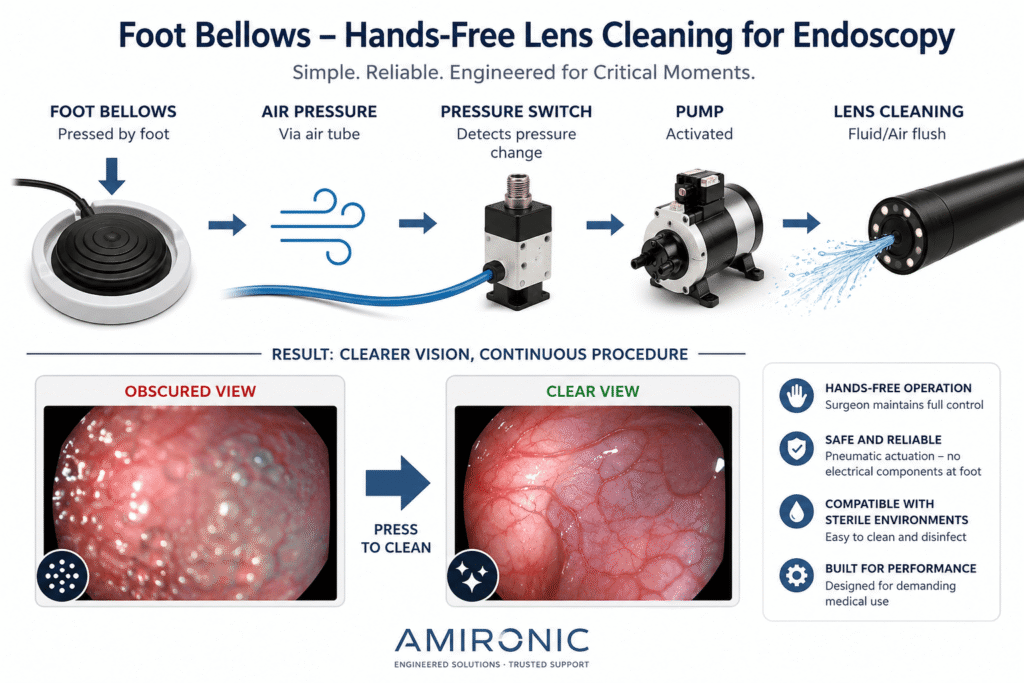
Endoscopy lens cleaning system using a pneumatic Foot Bellows – hands-free operation allows the physician to control the cleaning process while maintaining a continuous workflow throughout the procedure.

Why Is Pneumatic Actuation Particularly Interesting in Medical Equipment?

When using a pneumatic Foot Bellows, the pedal itself does not necessarily need to contain electrical contacts. Pressing the bellows changes the air pressure in the tube, while the electrical switching can take place elsewhere within the system.

This separation between the point of actuation and the point of electrical switching gives engineers significant design flexibility.

Instead of routing voltage and electrical wiring all the way to a pedal located on the floor, only an air tube needs to reach the Foot Bellows. The Pressure Switch and its connection to the control system can remain inside the equipment.

The advantage is not only electrical. The floor of a treatment room or operating room can be a challenging environment for any component: exposure to liquids, cleaning and disinfecting agents, repeated foot operation, and occasional mechanical impact all need to be considered.

The simpler the component located in this area can be, the easier it may be to address some of these system design challenges.

It is important to emphasize, however, that using a pneumatic Foot Bellows does not by itself make a medical system safe or compliant with any particular standard. Suitability for a medical application must be evaluated at the complete system level, taking into account the design, components, materials, and applicable standards.

More Than Just ON/OFF – Think About the User Experience

It is easy to think of a foot control as a simple switch: press it and the system operates; release it and the system stops.

But in medical equipment, even such a simple action has ergonomic implications.

The engineer should consider:

  • How much force is required for actuation?
  • Does the user receive a clear indication that the action has been performed?
  • Can the pedal be operated when the physician is standing at a less-than-ideal angle?
  • Does it remain stable on the floor?
  • Can it be operated repeatedly throughout a long procedure?
  • Is its construction suitable for the intended cleaning and disinfection methods?
  • What happens if the air tube is bent, crushed, or disconnected?

For this reason, selecting a Foot Control should not be a decision left until the final stages of system design. It is part of the device’s user interface.

What Happens if the Cleaning Mechanism Does Not Respond in Time?

Suppose the physician notices that image quality has deteriorated and presses the pedal to activate the cleaning system.

From the user’s perspective, the sequence should be almost intuitive:

Press → Clean → Clear View → Continue the Procedure

But behind this simple action is an entire chain of events.

The press must generate a sufficient pressure change. The tube must transmit it. The Pressure Switch must detect it reliably. The control system must respond. The pump must operate, and only then does the actual cleaning take place.

If any one of these stages is not designed correctly, the user may press the pedal and not receive the expected response.

This is exactly why a Foot Bellows should not be viewed as an isolated component, but rather as part of a complete system.

Foot Bellows or Electrical Footswitch – Which Is the Right Choice?

There is no single answer that fits every medical device.

An electrical Footswitch can be an excellent solution when a direct connection to the controller is required, when multiple commands are needed, or when the application requires feedback or more complex functionality.

A pneumatic Foot Bellows may be attractive when a simple actuation mechanism is preferred at floor level, when the electrical switching point can be located inside the equipment, or when the mechanical and environmental characteristics of the application make this separation advantageous.

The right question, therefore, is not:

“Which pedal is better?”

but rather:

“Which actuation method is better suited to the architecture of the device and the way the medical team uses it?”

That is an engineering decision.

The Same Principle Goes Far Beyond Lens Cleaning

The principle of Hands-Free Control is not limited to endoscope lens cleaning systems.

In various medical systems, a foot control can be used to activate functions where the user needs to keep both hands on the device, the patient, or the instruments being used.

Foot Controls can be found, for example, in suction systems, pumps, surgical equipment, dental systems, diagnostic equipment, and many other types of medical devices.

In each of these applications, the fundamental requirement is similar:

Perform an additional function without taking your hands away from the primary task.

And the more precision and concentration the primary task requires, the greater the value of a Hands-Free interface.

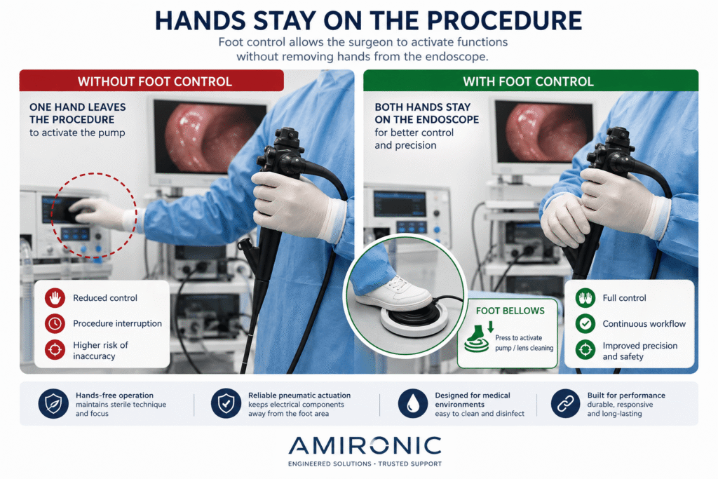
Foot Bellows control allows the physician to keep both hands on the endoscope while activating the cleaning system by foot – helping maintain control and continuity throughout the procedure.

Proper Design Starts Long Before Selecting the Foot Control

Once it has been decided that Foot Control is the appropriate method for activating a particular function, there are still several engineering decisions to be made.

In a pneumatic system, for example, the Foot Bellows, air tube, and Pressure Switch should be considered as a single system. A change in any one of these components can affect the feel and response of the entire system.

Tube length, internal diameter, air volume, the force required to press the bellows, and the sensitivity of the Pressure Switch can all influence how the user’s command is transmitted to the system.

The goal is to make the operation clear and predictable: the user presses the Foot Bellows – and the system responds as intended.

What Should You Consider When Selecting a Foot Bellows?

In a medical application, finding a pedal that fits mechanically is not enough. The system’s operating conditions should be considered from the requirements-definition stage.

Actuation Force

A pedal that requires too much force may become tiring during repeated use. On the other hand, a pedal that is too easy to activate may increase the risk of unintended actuation.

The required actuation force should therefore be matched to the actual use case rather than simply selecting the smallest or least expensive component.

Mechanical Stability

A Foot Bellows is positioned on the floor and may be pressed many times. Its design should allow consistent operation even when the user does not press directly in the center.

The design of the pedal base and the way it is positioned or secured on the floor can also have a significant impact on the user experience.

Resistance to Liquids and Cleaning

Medical equipment is frequently subjected to cleaning and disinfection procedures. It is therefore important to evaluate not only the actuation mechanism itself, but also the construction materials and their compatibility with the cleaning agents expected to be used.

Tube Length and Routing

A tube that is too short limits where the pedal can be positioned. A tube that is too long may interfere with the working environment, while in a pneumatic system the effect of tube volume on system response should also be considered.

The tube should also be routed in a way that minimizes the risk of bending, crushing, or accidental pulling.

Compatibility with the Pressure Switch

A Foot Bellows does not operate in isolation.

The pressure change generated when the bellows is pressed must be compatible with the actuation range of the Pressure Switch. An incorrect combination of these components may result in inconsistent operation or require an unnatural amount of force from the user.

Case Study – Endoscope Lens Cleaning System

Consider a system in which the endoscope tip needs to be cleaned during a procedure.

The initial requirement may sound simple:

“The physician must be able to activate the cleaning pump.”

But when this requirement is broken down at the system level, the picture becomes much more complex.

The physician needs to activate the pump without letting go of the endoscope. Operation should be intuitive. The pedal is located on the floor and must therefore be suitable for the intended working environment. The actuation mechanism should remain reliable over a large number of operating cycles, and the system should respond predictably every time the pedal is pressed.

One possible solution is a pneumatic Foot Bellows connected by an air tube to a Pressure Switch located inside the equipment.

When the physician presses the Foot Bellows, a change in air pressure is generated. The Pressure Switch detects this change and sends a command to the control system, which activates the pump. Fluid or air is then delivered to the endoscope tip to help clean the optical area.

When the physician releases the Foot Bellows, the system returns to its intended state.

What appears to be a simple action from the outside is therefore actually a combination of:

Ergonomics + Pneumatics + Switching + Pump Control + Medical Device Design

What Happens After Thousands of Activations?

This is an aspect that can easily be overlooked during the prototype stage.

In the laboratory, an engineer may press the pedal ten times, confirm that the system works, and move on.

In a commercial product, however, the component may undergo a very large number of operating cycles throughout its service life.

It is therefore important to evaluate not only whether the system works on day one, but also how it behaves after repeated use.

Does the Foot Bellows material retain its mechanical properties? Does the tube connection remain airtight? Does the actuation point remain consistent? Does the user receive the same response after extended use?

In medical equipment, Repeatability can be just as important as the ability to perform the function itself.

Test the Complete System – Not Just Each Individual Component

The Foot Bellows may meet its specifications. The Pressure Switch may also meet its specifications. The pump may operate exactly according to the manufacturer’s data.

And yet, the complete system may still fail to behave as the user expects.

This is why, during development, it is important to test the entire actuation chain:

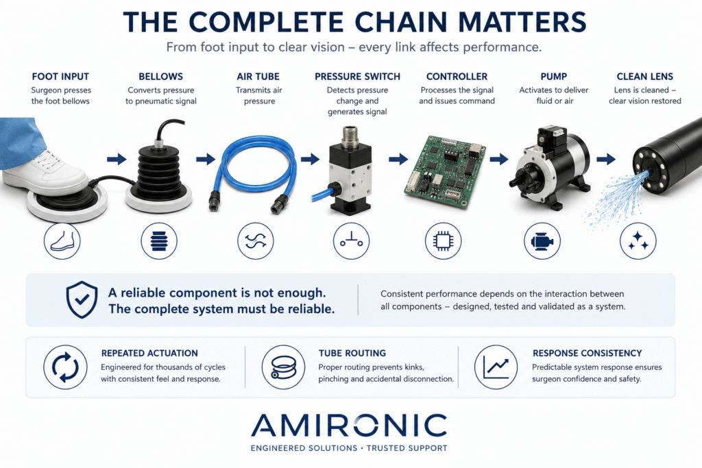
Foot → Bellows → Air Tube → Pressure Switch → Controller → Pump → Lens Cleaning

Particular attention should be given to less-than-ideal scenarios: partial presses, short presses, repeated activation, long tubing, temperature changes, pedal movement, and a large number of operating cycles.

The real test is not whether every individual component meets its datasheet specifications.

The real test is whether the complete system responds consistently to the user’s action.

The actuation chain in an endoscope lens cleaning system – from pressing the Foot Bellows to restoring a clear view.

Practical Example – Herga 6448 Foot Bellows

A good example of a component that fits this approach is the Herga 6448 Foot Bellows. It is a low-profile Foot Bellows designed for simple foot operation. It can be used as a free-standing unit on the floor or secured using its built-in mounting ring.

One of the advantages of the 6448 Series is the ability to configure the component to suit the system architecture. Options include side or rear tube entry, a flat base with or without a mounting ring, and a flexible-base version with double volume.

The tubing is also available in several configurations. The manufacturer offers tubing with a 3 mm internal diameter and 6 mm outside diameter, as well as a smaller option with a 1.5 mm internal diameter and 3 mm outside diameter for applicable configurations. Standard tube lengths range from 1.5 to 6 meters, with a curly coil tube also available.

Mechanically, the component is compact. According to the datasheet drawing, the version shown has an outside diameter of approximately 94 mm and a height of approximately 34 mm. In versions with a mounting ring, the unit can be secured using fixing holes on a 70 mm PCD.

The 6448 is made from thermoplastic, weighs approximately 0.1 kg, and is specified for an operating temperature range of -10°C to +40°C. The stated degree of protection is IPX4.

Why Do These Specifications Matter to the System Designer?

The advantage is that the engineer is not simply selecting a “pedal.” Several parameters can be adapted to the architecture of the device, including tube entry direction, mounting method, tube type, and tube length.

For example, in an endoscopy system where the control unit is located several meters away from the physician, the tube length can be selected according to the equipment layout. If the Foot Bellows needs to remain in a fixed position, a version with a mounting ring can be used. Different tube entry configurations are also available to accommodate different system layouts.

It is equally important not to attribute characteristics to the 6448 that are not stated in the datasheet. The manufacturer specifies IPX4, while the Standards/Approvals field is listed as N/A. Therefore, the fact that the component can be integrated into a medical application does not, by itself, indicate compliance with any specific medical standard. Its suitability for medical equipment must be evaluated as part of the design and validation of the complete system.

This is ultimately the key point: a Foot Bellows is a relatively simple component, but when properly integrated into a system, it can solve an important Human-Machine Interface challenge – allowing the user to activate a function without taking their hands away from the primary medical task.

Example Part Number

The datasheet lists 6448-AAAB-0000 as the stock model.

Summary

A dirty lens during an endoscopic procedure may initially appear to be a simple optical problem, but solving it requires a broader view of the complete system.

When the physician needs both hands to perform the procedure, even a simple task such as activating a lens-cleaning pump becomes a Human-Machine Interface challenge. Foot Control allows a secondary function to be transferred to the foot, leaving both hands available for the primary task.

A pneumatic Foot Bellows adds another interesting possibility: the point of actuation itself does not necessarily need to contain electrical switching. Pressing the bellows creates a change in air pressure, while the actual switching can take place through a Pressure Switch located elsewhere in the system.

But selecting the Foot Bellows is only part of the solution. The tubing, Pressure Switch, control system, and pump must work together as a complete system, providing consistent and reliable response over repeated operating cycles.

The Herga 6448 is an example of a compact Foot Bellows that can be configured with different tube entry, mounting, tube type, and tube length options to suit the architecture of the system.

Ultimately, the objective is not simply to clean the lens.

The objective is to allow the physician to quickly restore a clear view while maintaining control of the device and continuity throughout the procedure.

And sometimes, the solution to an optical problem begins right under the user’s foot.

🧩 Further Reading

This article is part of a broader series exploring how footswitches function as critical human-machine control interfaces across medical and industrial systems. For additional technical context and application insights, you may also find the following articles useful:

  • HERGA Control Solutions: More Than a Footswitch – The Human Interface That Defines System Performance
  • HERGA Medical Footswitches: Engineering the Right Control Interface for Clinical Systems
  • HERGA Industrial Footswitches: Reliable Control Solutions for Harsh and High-Duty Environments
  • Pneumatic Footswitches in Medical and Aesthetic Equipment
  • Industrial Safety Footswitches: Reliable Machine Control for Heavy-Duty and High-Risk Environments
  • Wired vs Wireless (Bluetooth) Footswitches: When Does It Actually Matter?
  • Footswitches for Medical and Aesthetic Laser Systems – Not Just a Trigger, but a Critical Part of System Safety
  • Medical Footswitches for IEC / UL 60601-1 Systems – Safety, Reliability and Design Considerations Every Engineer Should Know
  • 6 Switching Technologies Every Systems Engineer Should Know – And How to Choose the Right One
  • Why Foot Switches Fail – And What Experienced OEM Designers Do Differently
  • Pneumatic Foot Bellows vs. Electrical Footswitch – Do You Really Need to Run Electricity to the Foot Pedal?
  • Momentary or Latching? How to Choose the Right Switch for Industrial, Medical, and OEM Applications
  • Why Did Your Footswitch Fail After Just Six Months – Even Though It Was Rated for One Million Operations?
  • USB Foot Pedals for Medical & Industrial Systems – Why the USB Connector Is Only Part of the Story
  • Don’t Design a New Footswitch – Build It from a Modular Platform
  • Why Wireless Footswitches Are Becoming the Standard in Mobile Medical Equipment

Frequently Asked Questions (FAQ)

What Is a Foot Bellows?

A Foot Bellows is a pneumatic actuation mechanism operated by foot. Pressing the bellows creates a change in air pressure, which can be transmitted through a tube to a Pressure Switch or another control mechanism.

What Is the Difference Between a Foot Bellows and an Electrical Footswitch?

An electrical Footswitch contains an electrical switching mechanism in the pedal itself. With a Foot Bellows, pressing the pedal generates a pneumatic signal, allowing the electrical switching mechanism to be located elsewhere within the system.

Why Use Foot Control in Endoscopy Systems?

Foot-operated control allows the physician to continue holding and controlling the endoscope with both hands while simultaneously activating another function, such as a pump used as part of the lens cleaning system.

Can a Foot Bellows Activate a Pump Directly?

Typically, the Foot Bellows acts as the pneumatic control element. The pressure change is transmitted to a Pressure Switch, which can then send a command to the control system or pump, depending on the device architecture.

Is the Herga 6448 an Electrical Component?

The 6448 is a pneumatic Foot Bellows. The connection specified in the datasheet is through pneumatic tubing rather than an electrical connection.

What Mounting Options Are Available for the Herga 6448?

The 6448 Series offers several configurations, including side or rear tube entry, a flat base with or without a mounting ring, and a flexible-base option with double volume.

What Tube Lengths Are Available for the Herga 6448?

The datasheet lists standard tube lengths of 1.5, 2, 3, 4, 5, and 6 meters. A curly coil tube option is also available, as well as configurations supplied without tubing.

Is the Herga 6448 Water Resistant?

The manufacturer specifies a degree of protection of IPX4. The limitations of this protection rating should therefore be considered when designing the system and defining its cleaning procedures.

Is the Herga 6448 Approved for Medical Use?

The Standards/Approvals field in the 6448 datasheet is listed as N/A. Therefore, the datasheet alone should not be interpreted as indicating compliance with any specific medical standard. Suitability for medical equipment must be evaluated as part of the design and validation of the complete system.

What Should Be Considered When Selecting a Foot Bellows for Medical Equipment?

Important considerations include the mounting method, actuation force and feel, tube length and routing, environmental conditions, cleaning and disinfection requirements, compatibility with the Pressure Switch, and the expected number of operating cycles. Ultimately, it is not enough for each component to work independently – the complete actuation chain must provide a consistent and predictable response.

Key Terms

Foot Bellows – A pneumatic actuation mechanism in which foot pressure creates a change in air pressure that is transmitted through tubing to the system.

Footswitch – A foot-operated switch that allows the user to control a device function without using their hands.

Pneumatic Actuation – Activating a mechanism through a change in air pressure rather than transmitting an electrical signal directly from the point of actuation.

Pressure Switch – A component that detects a change in pressure and converts it into an electrical switching action.

Hands-Free Control – A control interface that allows the user to activate an additional function by foot while keeping both hands available for the primary task.

Human-Machine Interface (HMI) – The means by which a user interacts with and controls a device. In medical equipment, this may include switches, pedals, buttons, displays, and user feedback.

Endoscopy – The use of an endoscope to view internal areas of the body for diagnostic or therapeutic purposes.

Lens Cleaning System – A system designed to help maintain a clear field of view at the endoscope tip using fluid, air, or another suitable cleaning mechanism.

Tube Routing – The planned path of pneumatic tubing within a system, taking into account tube length, bending, crushing, connections, and potential interference with the user.

Repeatability – The ability of a system to provide a similar and consistent response during repeated operation.

IPX4 – The degree of protection specified for the Herga 6448 according to EN 60529.

Mounting Ring – A component used to secure the Foot Bellows to a surface rather than operating it as a free-standing unit. The 6448 is available in configurations with or without a mounting ring.

Tags: Herga

Related Articles

Medical Footswitch Design Platform: A Modular Solution for Precision in Healthcare

26/02/2025amironicLTD

USB Footswitches – USB-C Now Available!

04/03/2025amironicLTD

6461 Infra-Red Non-Contact Switch

07/09/2025amironicLTD

Recent Posts

  • Why Every Battery Pack Needs a Temperature Sensor – Not Just Electric Vehicles
  • Why a Dirty Lens Is More Than Just an Optical Problem – It’s an Engineering Challenge in Endoscopy Systems
  • The Antenna Hasn’t Moved – So Why Did We Lose the Link? The Role of the IMU in Antenna Positioning Systems
  • Why a Standard Thermal Circuit Breaker Isn’t Always the Right Choice for Data Centers
  • How Does a MEMS Sensor Become a Tactical-Grade IMU?

Categories

  • Air Switch
  • Circuit Breakers
  • Elapsed Time Indicator
  • Feedthrough
  • Footswitches
  • Gears & Transmission
  • Hour Meters
  • Infra Red Switches
  • INFRARED LAMPS
  • Low Noise Inertial MEMS
  • Mechanics
  • MEMS Gyroscope
  • MEMS Inertial
  • Microelectronics
  • Motors
  • Position Sensors
  • Power Supply
  • Pressure Sensors
  • Pressure Switch
  • Temperature Sensors
  • Tungsten and Molybdenum
  • Uncategorized
  • Vacuum Switches

Quick Contact

Fill out the form and our representatives will return to you

    Name (required)

    Email (required)

    Phone

    Message

    This site is protected by reCAPTCHA and the Google
    Privacy Policy and
    Terms of Service apply.

    Amironic Ltd.

    3 Rabinovich Street, Petah Tikva 4928144 , Israel. Tel: +972-3-9047744 E-mail: office@amironic.co.il
    Email
    Facebook
    Twitter
    LinkedIn
    YouTube
    Press on the ISO Certificate below for download
    ISO 9001:2015 Certification
    • MEMS Inertial
    • Circuit Breakers
    • Footswitches
    • Mechanical & Transmisions
    • Sensors
    • Motors
    • Electronics
    • Hand Control
    • Power Solutions

    News

    • Why Every Battery Pack Needs a Temperature Sensor – Not Just Electric Vehicles
    • Why a Dirty Lens Is More Than Just an Optical Problem – It’s an Engineering Challenge in Endoscopy Systems
    • The Antenna Hasn’t Moved – So Why Did We Lose the Link? The Role of the IMU in Antenna Positioning Systems
    • Why a Standard Thermal Circuit Breaker Isn’t Always the Right Choice for Data Centers
    • How Does a MEMS Sensor Become a Tactical-Grade IMU?
    About AmironicContactעברית
    © 2022 Amironic All rights reserved. All Trademarks are the property of their respective owners.
    • Increase Font
    • Decrease Font
    • Black & White
    • Inverse Colors
    • Highlight Links
    • Regular Font
    • Reset