flagעברית
flagEnglish
3 Rabinovich St., Petah-Tikva, Israel
+972 3 9047744
office@amironic.co.il
Facebook
Twitter
LinkedIn
YouTube
  • Products
    • MEMS Inertial
      • Gyros & Accels
      • IMU
      • Inertial Navigation
      • AHRS
    • Circuit Breakers
      • Airpax Circuit Breakers
      • Electronic Circuit Breakers
      • Aircraft Circuit Breakers
      • Thermal Circuit Breakers
      • Sealing Solutions & Guards
    • Footswitches
      • Pedals & Bellows
      • USB
      • Air Switches
      • Medical
      • Modular Bases System
      • Industrial
      • Foot Potentiometers
      • Wireless
    • Mechanical & Transmisions
      • Gears
      • Sealing Solutions
      • Gearboxes
      • Couplings
      • Shafts & Bearings
      • Fasteners
      • Mechanical & Springs
      • Linear Motion
      • Anti-Vibration
    • Sensors
      • Thermostats
      • Temperature
      • Position
      • Pressure
      • Speed
      • Level Sensor
      • Load Cells
      • Flex Sensors
      • Membrane Potentiometer
    • Motors
      • Geared DC
      • Brushless DC
      • Step Motors with Gearbox
      • Torque Motors & Brushless Servo
      • DC Motors
    • Electronics
      • Xenon & IR Lamps
      • Counters & Meters
      • Microelectronics Packaging
      • Waterproof Switches
      • Micro Switches
    • Hand Control
      • Operator Controls (JOYSTICK)
      • Electrical
      • Pneumatic (Medical)
      • USB Hand Control
      • Air Push Button
      • Pressure Switch
      • IR Switch
    • Power Solutions
      • Rugged & Military Power Supply
      • Input Power Protection
      • Sealed Military Power Adaptor
      • Triple Output Military Power Supply Series – up to 250 W
    • Materials
      • Molybdenum and Advanced Alloys (TZM, MOLA, HCT)
      • Tungsten (Wolfram) and Advanced Alloys – High-Performance Materials for Extreme Conditions
      • Materials for Gears
  • Shop
  • Companies
  • About Amironic
  • News
  • Contact
Product was added to your cart

Cart

waze

When GPS Is Lost, It’s Already Too Late to Choose an IMU

MEMS Gyroscope, MEMS Inertial21/07/2026amironicLTD

How an Early IMU Selection Can Determine Whether Your System Continues Navigating After GPS Is Lost

We’re all familiar with navigation systems that display an accurate position on a map, follow a planned route, and provide real-time velocity and heading information. As long as GPS reception is available, it’s easy to assume that GPS alone is responsible for this level of accuracy.

In reality, however, many systems used in defense applications, aerospace, autonomous platforms, and naval systems face a much more important question: not what happens when GPS is available, but what happens the moment it is no longer available.

Today, GPS outages are no longer rare events. Jamming, spoofing, operation inside buildings or tunnels, dense urban environments, forests, canyons, and contested battlefield conditions can all force a navigation system to continue operating without any external position updates.

That is the moment when the difference becomes apparent between a system that continues to provide reliable navigation data and one whose position, velocity, and attitude errors begin to grow rapidly.

And that difference often comes down to a single engineering decision made months, or even years, earlier:

Which IMU was selected for the system.
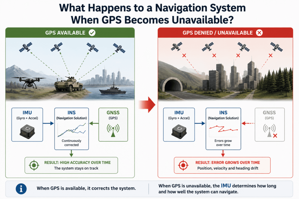
Figure 1 – As long as GNSS updates are available, the navigation system continuously corrects accumulated errors. When GNSS signals become unavailable, the system relies solely on the IMU, and errors in position, velocity, and attitude begin to grow over time.

What Really Changes When GPS Is Lost?

It’s easy to assume that a navigation system simply “stops working” when GPS signals are lost. In reality, that is not what happens.

In an Inertial Navigation System (INS), the IMU continues to measure the platform’s linear accelerations and angular rates continuously, even when no external navigation information is available. The navigation algorithm continues calculating position, velocity, and attitude just as it did before.

The difference is that once GPS updates are no longer available, there is no external reference to correct the accumulated navigation errors.

Every inertial sensor, regardless of its quality, has inherent imperfections. Bias, measurement noise, scale factor errors, and temperature effects are all part of every IMU. While GPS updates are available, the navigation system continuously estimates and corrects most of these errors. Once those updates disappear, however, each of these small error sources begins to accumulate over time.

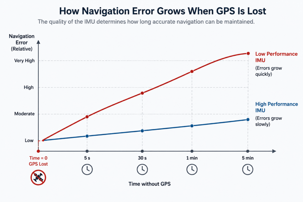
Initially, the effect is almost imperceptible. For the first few seconds, the navigation solution may remain highly accurate. As time passes without external corrections, however, the accumulated error continues to grow.

For this reason, the real question is not whether an INS can continue operating without GPS. The more important question is how long it can continue providing navigation data that is accurate enough for the mission.

That is precisely the point at which IMU performance becomes a critical factor.

Figure 2 – Without GNSS updates, the navigation system relies entirely on IMU measurements. As time passes, navigation errors continue to accumulate. A high-performance IMU significantly slows the rate of error growth compared to a lower-performance IMU.

Which IMU Characteristics Really Matter When GPS Is Unavailable?

When engineers compare two IMUs, it’s easy to focus on the specifications listed at the top of the datasheet. In a GPS-denied environment, however, not all parameters have the same impact on navigation performance.

The reason is straightforward. Without external updates, every small measurement error is carried into the next navigation calculation instead of being corrected. Over time, these seemingly insignificant errors accumulate and can eventually lead to substantial errors in position, velocity, and attitude.

Among the most important IMU characteristics are:

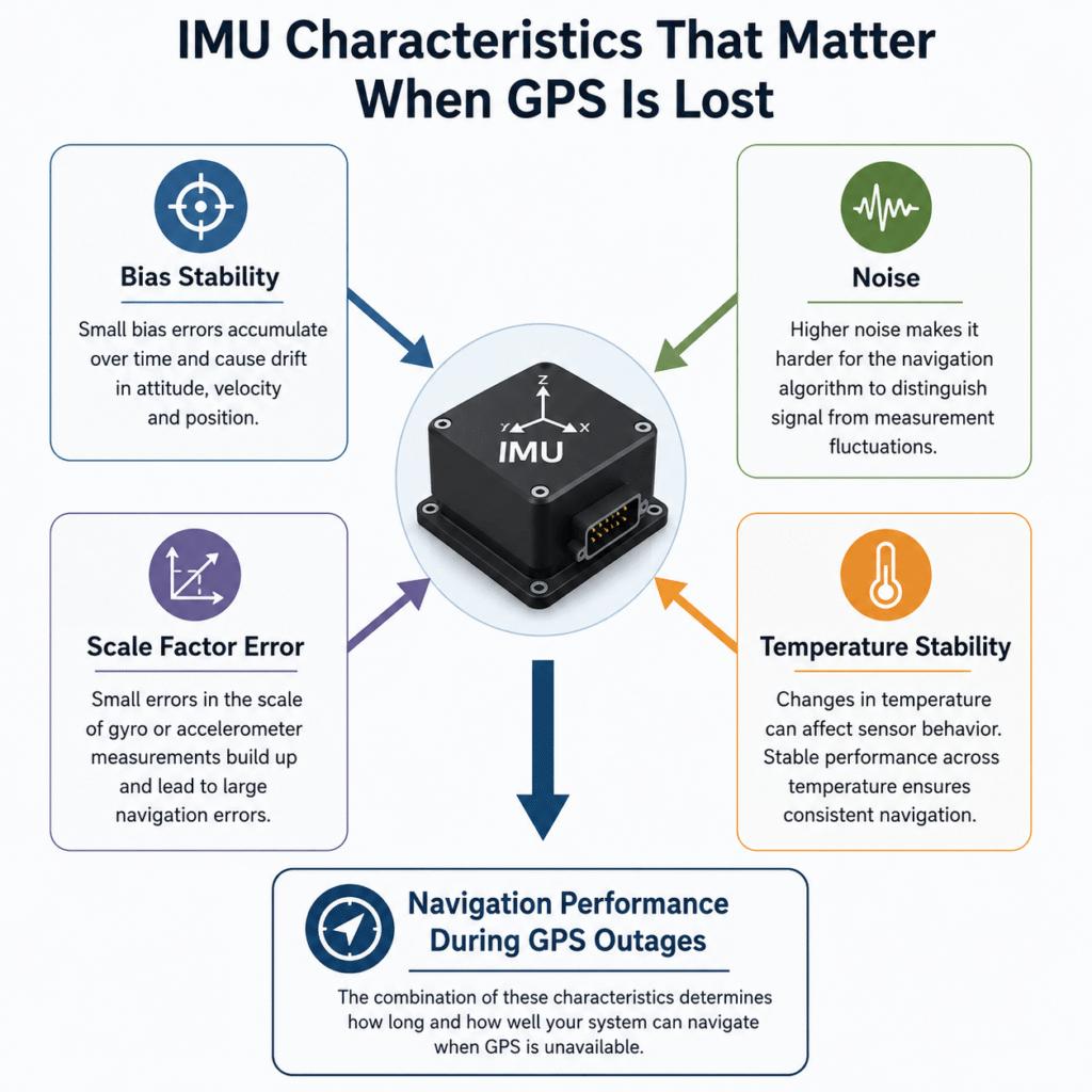
Bias Stability – A small but persistent offset in the output of the gyroscopes or accelerometers. Although the bias may appear negligible, it continuously affects every navigation update. The longer the system operates without external corrections, the greater its impact becomes.

Noise – Random variations in the sensor measurements. Higher noise levels make it more difficult for the navigation algorithm to distinguish real platform motion from measurement uncertainty.

Scale Factor Error – A deviation between the actual motion and the value reported by the sensor. Even a very small scale factor error in angular rate or acceleration measurements can accumulate over time and result in significant navigation drift.

Temperature Stability – Environmental conditions change in nearly every operational scenario. Temperature variations can affect sensor performance, making it essential to select an IMU that maintains stable performance across a wide operating temperature range.

It is important to recognize that no single specification defines the quality of an IMU. Overall navigation performance depends on the combination of all sensor characteristics, together with the manufacturer’s calibration processes, compensation techniques, and production quality.

This is also why two IMUs with seemingly similar datasheet specifications can deliver dramatically different performance once GPS is no longer available.

Figure 3 – IMU performance is not determined by a single specification. Instead, it is the combination of Bias Stability, measurement noise, Scale Factor Error, and temperature stability that determines how well a navigation system performs when GNSS updates are unavailable.

Can a Good Navigation Algorithm Compensate for a Lower-Performance IMU?

This is one of the most common questions asked by navigation system engineers.

At first glance, the answer seems to be “yes.” Modern navigation algorithms perform sensor fusion, filter measurement noise, detect anomalies, and continuously estimate and correct navigation errors. It is therefore tempting to assume that a lower-performance IMU can simply be compensated for in software.

In reality, the answer is more nuanced.

As long as GNSS updates or other external navigation references are available, the algorithm can estimate accumulated errors and continuously correct them. That is precisely what modern navigation algorithms are designed to do.

However, once the system enters a GPS-denied environment, those external references are no longer available.

From that moment on, the algorithm can only work with the data provided by the IMU.

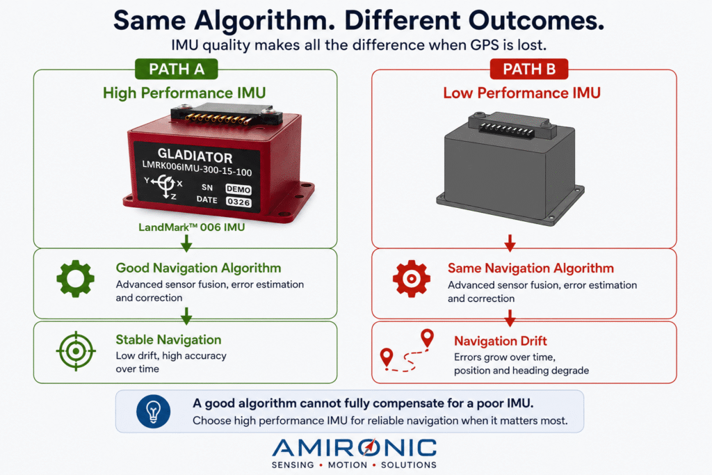
If the measurements contain bias, excessive noise, or scale factor errors, the algorithm cannot determine with certainty whether the observed motion represents the platform’s true movement or simply measurement error. In other words, it cannot recover information that was never measured in the first place.

This is why IMU quality and algorithm quality are not substitutes – they complement each other.

A high-performance IMU provides more stable and accurate measurements.

A high-quality navigation algorithm makes the best possible use of those measurements.

When either component is compromised, the overall performance of the navigation system is inevitably affected.

Figure 4 – Even the most advanced navigation algorithm cannot fully compensate for sensor limitations. When GNSS signals are unavailable, IMU performance becomes one of the primary factors determining both the rate of navigation error growth and the overall performance of the navigation system.

How to Choose an IMU for Applications Where GPS May Be Lost

There is no single IMU that is ideal for every application. The right choice depends on how long the system is expected to operate without GNSS updates, the level of navigation accuracy required, and the environmental conditions in which it must perform.

Before selecting an IMU, engineers should consider several fundamental questions:

  • How long must the system continue navigating without GPS – seconds, minutes, or longer?
  • Does the application require stabilization only, or accurate navigation over extended periods?
  • Will the platform operate in an environment with significant vibration, high dynamics, or extreme temperature variations?
  • Is precise synchronization with cameras, radar, LiDAR, or other sensors required?
  • What is the minimum navigation accuracy the system must maintain during a GNSS outage?

The longer a system must operate without external navigation updates, the more important IMU performance becomes. Characteristics such as Bias Stability, measurement noise, Scale Factor Error, and temperature stability play an increasingly important role because they directly influence the rate at which navigation errors accumulate.

In many projects, the IMU is selected during the earliest stages of system development, long before the navigation algorithm is finalized or field testing begins. That early engineering decision can have a lasting impact on the system’s performance throughout its operational lifetime.


Conclusion

When GPS is available, most navigation systems deliver impressive performance.

The real differences only become apparent when GNSS updates are no longer available.

At that point, IMU performance becomes one of the most important factors determining whether a navigation system can continue providing reliable position, velocity, and attitude information. While advanced navigation algorithms can make better use of high-quality sensor data, they cannot recover information that was never measured.

For this reason, selecting an IMU is far more than choosing an electronic component. It is a fundamental engineering decision that directly affects system stability, the rate of navigation error growth, and ultimately the system’s ability to accomplish its mission when GPS is no longer available.

Case Study 1 – Maintaining Line of Sight During a GNSS Outage

Scenario

A tactical UAV is conducting an intelligence, surveillance, and reconnaissance (ISR) mission at an altitude of approximately 1,500 meters while tracking a vehicle located about 8 km away. During the mission, electronic jamming causes GNSS signals to become unavailable for several tens of seconds.

Despite the GNSS outage, the mission cannot simply stop. The EO/IR payload must continue stabilizing the image, keep the target centered within the field of view, and allow the operator to maintain accurate target tracking.

From this moment onward, both the navigation system and the stabilization control loops rely primarily on data provided by the IMU.

Two Different Challenges – Two Different IMU Requirements

An EO/IR payload actually performs two fundamentally different tasks.

The first is rapid stabilization of the line of sight against platform vibration, wind gusts, and vehicle maneuvers.

The second is maintaining pointing accuracy over time when the navigation system is no longer receiving GNSS updates.

Each task places different demands on the IMU.

Bandwidth, Output Rate, and Message Delay directly influence the responsiveness of the real-time stabilization loop.

Bias Stability, measurement noise, Scale Factor Error, and temperature stability determine how quickly navigation errors accumulate once external corrections are no longer available.

How Significant Can a Small Angular Error Be?

The ground displacement caused by an angular pointing error can be approximated by:

Ground Offset = Distance × tan(Angular Error)

For a target located 8,000 meters away, the resulting offsets are approximately:

Angular Error Ground Offset
0.005° 0.70 m
0.01° 1.40 m
0.02° 2.79 m
0.05° 6.98 m
0.10° 13.96 m

At first glance, an angular error of 0.01° may appear insignificant. At a distance of 8 km, however, it already corresponds to approximately 1.4 meters on the ground.

When tracking a vehicle, antenna, observation post, or individual, even a few meters of pointing error may shift the target away from the center of the image, reduce automatic tracking performance, degrade coordinate accuracy, and ultimately decrease mission effectiveness.

How Does the IMU Help?

Meeting these requirements involves far more than optimizing a single IMU specification. Overall system performance depends on the combination of dynamic response, measurement quality, and long-term stability.

For example, the LandMark™ 006 IMU features:

  • Typical Bias Stability of 0.8°/hr
  • Angle Random Walk of 0.0254°/√hr
  • Bandwidth up to 600 Hz
  • Output Rate up to 10 kHz
  • Message Delay of less than 20 µs
  • Full calibration over a temperature range of -50°C to +85°C

In practice, the high bandwidth and output rate help the stabilization loop respond quickly to platform vibration and dynamic maneuvers. The extremely low message delay minimizes latency between platform motion and control system response, while Bias Stability and Angle Random Walk contribute to maintaining a stable attitude estimate when GNSS updates are unavailable.

It is important to note that actual pointing accuracy cannot be predicted directly from datasheet specifications alone. Final system performance also depends on the navigation algorithms, stabilization architecture, GNSS outage duration, platform dynamics, and the integration of other onboard sensors.

Conclusion

When GNSS is available, maintaining accurate line of sight is relatively straightforward.

The real challenge begins when GNSS updates are lost.

At that point, IMU performance becomes one of the key factors determining whether the EO/IR payload can continue keeping the target centered or whether pointing errors will gradually accumulate over time.

For this reason, selecting an IMU for tactical EO/IR systems is far more than choosing an electronic component. It is an engineering decision that directly influences overall mission performance.

Case Study 2 – Laser Designator: When Hundredths of a Degree Become Meters on the Target

Case Study 2 – Laser Designator: When Hundredths of a Degree Become Meters on the Target

Scenario

An EO/IR payload mounted on a tactical UAV identifies a target and activates a laser designator to accurately mark a point on the ground.

The target is approximately 12 km away while the UAV continues to maneuver, vibrate, and experience wind disturbances throughout the designation process. At the same time, GNSS signals are being jammed, preventing the system from relying on continuous external position and attitude updates.

Under these conditions, the stabilization system must keep both the line of sight and the laser beam pointed at the same location despite platform motion and the gradual accumulation of inertial navigation errors.

How Significant Can a Small Pointing Error Be?

The displacement of the laser spot on the ground can be approximated by:

Ground Offset = Range × tan(Angular Error)

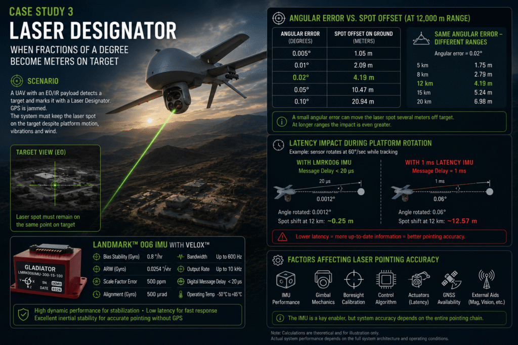
For a target located 12,000 meters away:

Angular Error Approximate Laser Spot Offset
0.005° 1.05 m
0.01° 2.09 m
0.02° 4.19 m
0.05° 10.47 m
0.10° 20.94 m

An angular pointing error of only 0.02° can therefore shift the laser spot by more than 4 meters.

When the designated point is a vehicle, building entrance, antenna, fortified position, or another precisely defined location, an offset of several meters is no longer negligible. It may move the laser designation from one part of the target to another or, in some situations, beyond the intended target area altogether.

The Effect Becomes More Significant at Longer Ranges

The resulting ground offset increases almost linearly with target distance.

For an angular error of 0.02°:

Target Range Approximate Ground Offset
5 km 1.75 m
8 km 2.79 m
12 km 4.19 m
15 km 5.24 m
20 km 6.98 m

The same angular error produces less than 2 meters of offset at 5 km, but nearly 7 meters at 20 km.

For this reason, angular accuracy specifications should always be evaluated in the context of the system’s actual operational range.

Fast Stabilization Versus Long-Term Pointing Accuracy

A laser designation system must solve two fundamentally different problems.

The first is rejecting rapid disturbances caused by platform vibration, propulsion, wind gusts, and vehicle maneuvers. The stabilization loop must measure these motions and compensate for them in real time.

The second is maintaining accurate pointing over extended periods. Even when the image appears perfectly stable, small gyroscope errors can gradually cause the estimated pointing direction to drift whenever external navigation updates are unavailable.

As a result, a system may appear visually stable while the laser beam slowly moves away from the intended geographic point.

How Does the IMU Help?

Applications such as this require a combination of dynamic performance and long-term inertial stability.

According to the manufacturer’s preliminary specifications, the LandMark™ 006 IMU provides:

  • Typical gyroscope Bias Stability of 0.8°/hr
  • Angle Random Walk of 0.0254°/√hr
  • Scale Factor Error of 500 ppm
  • Gyroscope Alignment accuracy of 500 µrad
  • Bandwidth up to 600 Hz
  • Output Rate up to 10 kHz
  • Digital Message Delay of less than 20 µs
  • Full calibration over a temperature range of -50°C to +85°C

The high bandwidth and output rate help the stabilization loop detect and compensate for rapid platform motion.

The extremely low message delay minimizes the time between actual platform movement and the availability of measurement data within the control computer.

Bias Stability and Angle Random Walk contribute to maintaining a stable attitude estimate when continuous external corrections are unavailable.

Scale Factor Error, sensor alignment, and temperature stability influence measurement consistency during vehicle maneuvers, temperature variations, and extended operation.

An Example of Why Message Delay Matters

Assume the EO/IR payload is rotating at 60°/second while tracking a moving target.

With a 20 µs message delay, the angular motion occurring during that delay is:

60 × 20 × 10⁻⁶ = 0.0012°

At a range of 12 km, this corresponds to approximately:

12,000 × tan(0.0012°) ≈ 0.25 meters

With a 1 ms delay:

60 × 0.001 = 0.06°

At the same range:

12,000 × tan(0.06°) ≈ 12.57 meters

This is a simplified geometric illustration rather than a prediction of actual pointing error. Modern control systems can compensate for portions of the delay through prediction and filtering, while total system latency also includes cameras, processors, communication links, and actuators. Nevertheless, the example demonstrates why IMU message delay is an important consideration in dynamic pointing systems.

Distinguishing IMU Error from Overall System Error

An IMU specification such as Bias Stability cannot be directly converted into laser pointing accuracy.

Actual system performance also depends on factors including:

  • EO/IR payload calibration quality
  • Structural stiffness and mechanical interfaces
  • Encoder accuracy
  • Tracking and stabilization algorithms
  • IMU alignment relative to the optical axis
  • Camera and actuator latency
  • GNSS outage duration
  • Additional aiding sources such as magnetometers, star trackers, or vision-based navigation

The IMU therefore does not determine pointing accuracy by itself, but it remains one of the fundamental components supporting the entire pointing chain.

Conclusion

In a tactical laser designation system, hundredths of a degree are not insignificant.

At a range of 12 km, an angular error of 0.02° corresponds to more than 4 meters on the ground. At 20 km, the same error approaches 7 meters.

Selecting an IMU for a laser designation system is therefore about far more than image stabilization. It directly influences pointing accuracy, laser spot placement, coordinate quality, and ultimately the system’s ability to continue performing its mission when GNSS conditions become unreliable.

🧩 Further Reading and Deeper Insight

This article is part of a broader series exploring the engineering principles behind modern inertial sensing and motion stability in advanced control and navigation systems. For deeper technical context and system-level insights, you may also find the following articles valuable:

  • Bridging Control and Navigation: How Advanced MEMS IMUs Are Redefining System Performance
  • Gyro and IMU for Advanced Control Systems
  • The Silent Problem of Precision Systems – Why Gyros and IMUs Are Control Components, Not Just Sensors
  • Why External Sync is Critical in Gyro and IMU Systems
  • Stabilization, Tracking & Time Sync: The Foundation of Precise Line-of-Sight Control
  • Mission-Grade Stabilization in Dynamic EO/IR Systems: Why Bandwidth, Data Rate, and Phase Lag Define Gimbal Performance
  • Why Gladiator? What Truly Differentiates a High-End MEMS IMU Manufacturer
  • Common Misconceptions About MEMS Inertial Sensors
  • Bias Stability vs. Bias Instability: What really determines the performance of Gyro and IMU systems in stabilization, tracking, and navigation
  • Scale Factor in MEMS IMUs – The Error That Quietly Destroys Accuracy
  • The IMU Was Excellent. The Image Still Shook.
  • 2000Hz IMU? Before You Get Impressed, Understand Three Completely Different Numbers
  • SX3: Pushing MEMS Beyond Traditional Stabilization
  • Why a Smaller IMU Can Save Months of Development
  • Your Image Still Shakes Despite Choosing a Gyroscope with Excellent Bias Stability
  • Why Replacing an IMU Can Lead to Weeks of Recalibration
  • From IMU to INS: How a Tactical Navigation System Is Really Built

Frequently Asked Questions (FAQ)

Can an EO/IR system continue tracking a target when GNSS is unavailable?

Yes. EO/IR systems do not stop operating when GNSS signals are lost. The IMU continues measuring platform motion, while the stabilization system compensates for vibration and vehicle maneuvers. However, the longer the GNSS outage lasts, the greater the influence of IMU performance on navigation error growth and line-of-sight accuracy.


Can a high-performance IMU replace an Inertial Navigation System (INS)?

No. An IMU provides measurements of linear acceleration and angular rate only. An INS combines IMU data with navigation algorithms and, in many cases, additional aiding sources such as GNSS, vision-based navigation, Doppler Velocity Logs (DVLs), or star trackers.

However, the performance of an INS can never exceed the quality of the measurements provided by its IMU.


Which IMU specification is most important for tactical applications?

There is no single answer that applies to every application.

For high-speed stabilization and tracking systems, Bandwidth, Output Rate, and Message Delay are critical.

For tactical navigation systems, Bias Stability, Angle Random Walk (ARW), Scale Factor Error, and temperature stability have a major influence on navigation error growth during GNSS outages.

For this reason, IMU selection should always be based on mission requirements rather than on a single specification.


Why has GPS-denied navigation become such an important topic in defense systems?

GNSS jamming, spoofing, and electronic warfare have become increasingly common in modern operational environments. As a result, many tactical systems are now designed to continue operating even when satellite navigation is unavailable.

Under these conditions, the IMU becomes one of the most important sensors in the entire system.


Is high bandwidth important only for stabilization systems?

No.

High bandwidth enables the IMU to accurately measure rapid platform motion. It is therefore important not only for stabilization systems, but also for target tracking, EO/IR payloads, Counter-UAS systems, active protection systems (APS), and autonomous platforms performing aggressive maneuvers.


Why is Message Delay so important?

Every control loop depends on sensor data.

The earlier measurement data becomes available, the more current the information used by the control computer. In high-dynamic tactical systems with rapid rotational motion, even differences measured in microseconds can influence tracking accuracy and overall control performance.


Can software alone improve IMU performance?

Advanced navigation algorithms can reduce measurement noise, fuse data from multiple sensors, and improve state estimation.

However, when GNSS updates are unavailable, no algorithm can recover information that was never measured. For this reason, IMU measurement quality remains one of the fundamental factors determining overall system performance.


Where are IMUs used in modern tactical systems?

Today, IMUs are integrated into a wide range of defense and aerospace applications, including:

  • EO/IR payloads and stabilized imaging systems
  • Unmanned aerial vehicles (UAVs)
  • Loitering munitions
  • Counter-UAS systems
  • Active Protection Systems (APS)
  • Stabilized turrets and fire control systems
  • Inertial navigation systems for military vehicles
  • Stabilized naval platforms
  • Stabilized antennas and communication systems

Glossary

Bias Stability

The ability of a gyroscope or accelerometer to maintain a stable bias over time. Better Bias Stability results in slower navigation error growth when GNSS updates are unavailable.

Bandwidth

The frequency range over which an IMU can accurately measure dynamic motion. Higher bandwidth enables more accurate measurement of rapid platform movements, making it particularly important for stabilization and high-dynamic control applications.

EO/IR (Electro-Optical / Infrared)

An observation system combining daylight cameras, thermal imagers, and other sensors for target detection, identification, tracking, and surveillance.

External Sync

The capability to synchronize an IMU with cameras, LiDAR, radar, or other sensors using a common timing signal, ensuring that all measurements correspond to the same instant in time.

GPS-Denied Environment

An environment in which GPS or other GNSS signals are unavailable or unreliable due to jamming, spoofing, physical obstruction, or challenging operating conditions.

GNSS (Global Navigation Satellite System)

A collective term for satellite navigation systems such as GPS, Galileo, GLONASS, and BeiDou.

IMU (Inertial Measurement Unit)

A sensor that combines gyroscopes and accelerometers to measure angular rates and linear accelerations along three axes. The IMU serves as the primary motion sensor for stabilization and inertial navigation systems.

INS (Inertial Navigation System)

A navigation system that combines IMU measurements with navigation algorithms to continuously estimate position, velocity, and attitude, even when GNSS updates are unavailable.

Laser Designator

A system that projects a coded laser beam onto a target, enabling laser-guided systems to identify and accurately engage the designated point.

Line of Sight (LOS)

The imaginary line connecting a sensor or optical system to its target. Maintaining a stable line of sight is fundamental to tracking, surveillance, and targeting systems.

LOS Stabilization (Line of Sight Stabilization)

A stabilization technique that keeps a sensor or optical system pointed at the same location even while the platform experiences vibration, acceleration, or maneuvering. LOS stabilization is one of the primary applications of IMUs in EO/IR payloads, fire control systems, and stabilized surveillance platforms.

Message Delay

The time between an IMU measurement and the availability of that measurement to the control computer. Lower message delay allows the control loop to react using more up-to-date information.

Output Rate

The frequency at which an IMU transmits measurement data to the control computer. Higher output rates enable more frequent updates of the platform’s motion state.

Scale Factor Error

The deviation between actual motion and the value measured by the sensor due to gain inaccuracies. Scale Factor Error can accumulate over time and degrade navigation accuracy.

Tactical Navigation

Navigation for military and other mission-critical platforms operating in challenging environments where GNSS may be degraded or unavailable. These systems typically require high-performance IMUs and advanced navigation algorithms.

Target Tracking

The capability of an EO/IR or other sensing system to keep a target centered within its field of view while either the target or the platform is in motion.

VELOX™

Gladiator Technologies’ digital processing architecture, designed to support high output rates, low message delay, and wide bandwidth for demanding stabilization, control, and navigation applications.

Tags: Gladiator_Technologies

Related Articles

From IMU to INS: How a Tactical Navigation System Is Really Built

16/07/2026amironicLTD

The New Generation of MEMS Triaxial Gyro is here !

21/10/2017amironicLTD

Why a Smaller IMU Can Save Months of Development

30/06/2026amironicLTD

Recent Posts

  • When GPS Is Lost, It’s Already Too Late to Choose an IMU
  • USB Foot Pedals for Medical & Industrial Systems – Why the USB Connector Is Only Part of the Story
  • How to Calculate Gear Ratio and Choose the Right Gears
  • How Does an INS Algorithm Really Work?
  • Your Pressure Sensor May Be Accurate. Your Measurement May Not Be – Why a ±0.5% Accuracy Specification Doesn’t Guarantee a ±0.5% Measurement

Categories

  • Air Switch
  • Circuit Breakers
  • Elapsed Time Indicator
  • Feedthrough
  • Footswitches
  • Gears & Transmission
  • Hour Meters
  • Infra Red Switches
  • INFRARED LAMPS
  • Low Noise Inertial MEMS
  • Mechanics
  • MEMS Gyroscope
  • MEMS Inertial
  • Microelectronics
  • Motors
  • Position Sensors
  • Power Supply
  • Pressure Sensors
  • Pressure Switch
  • Temperature Sensors
  • Tungsten and Molybdenum
  • Uncategorized
  • Vacuum Switches

Quick Contact

Fill out the form and our representatives will return to you

    Name (required)

    Email (required)

    Phone

    Message

    This site is protected by reCAPTCHA and the Google
    Privacy Policy and
    Terms of Service apply.

    Amironic Ltd.

    3 Rabinovich Street, Petah Tikva 4928144 , Israel. Tel: +972-3-9047744 E-mail: office@amironic.co.il
    Email
    Facebook
    Twitter
    LinkedIn
    YouTube
    Press on the ISO Certificate below for download
    ISO 9001:2015 Certification
    • MEMS Inertial
    • Circuit Breakers
    • Footswitches
    • Mechanical & Transmisions
    • Sensors
    • Motors
    • Electronics
    • Hand Control
    • Power Solutions

    News

    • When GPS Is Lost, It’s Already Too Late to Choose an IMU
    • USB Foot Pedals for Medical & Industrial Systems – Why the USB Connector Is Only Part of the Story
    • How to Calculate Gear Ratio and Choose the Right Gears
    • How Does an INS Algorithm Really Work?
    • Your Pressure Sensor May Be Accurate. Your Measurement May Not Be – Why a ±0.5% Accuracy Specification Doesn’t Guarantee a ±0.5% Measurement
    About AmironicContactעברית
    © 2022 Amironic All rights reserved. All Trademarks are the property of their respective owners.
    • Increase Font
    • Decrease Font
    • Black & White
    • Inverse Colors
    • Highlight Links
    • Regular Font
    • Reset