flagעברית
flagEnglish
3 Rabinovich St., Petah-Tikva, Israel
+972 3 9047744
office@amironic.co.il
Facebook
Twitter
LinkedIn
YouTube
  • Products
    • MEMS Inertial
      • Gyros & Accels
      • IMU
      • Inertial Navigation
      • AHRS
    • Circuit Breakers
      • Airpax Circuit Breakers
      • Electronic Circuit Breakers
      • Aircraft Circuit Breakers
      • Thermal Circuit Breakers
      • Sealing Solutions & Guards
    • Footswitches
      • Pedals & Bellows
      • USB
      • Air Switches
      • Medical
      • Modular Bases System
      • Industrial
      • Foot Potentiometers
      • Wireless
    • Mechanical & Transmisions
      • Gears
      • Sealing Solutions
      • Gearboxes
      • Couplings
      • Shafts & Bearings
      • Fasteners
      • Mechanical & Springs
      • Linear Motion
      • Anti-Vibration
    • Sensors
      • Thermostats
      • Temperature
      • Position
      • Pressure
      • Speed
      • Level Sensor
      • Load Cells
      • Flex Sensors
      • Membrane Potentiometer
    • Motors
      • Geared DC
      • Brushless DC
      • Step Motors with Gearbox
      • Torque Motors & Brushless Servo
      • DC Motors
    • Electronics
      • Xenon & IR Lamps
      • Counters & Meters
      • Microelectronics Packaging
      • Waterproof Switches
      • Micro Switches
    • Hand Control
      • Operator Controls (JOYSTICK)
      • Electrical
      • Pneumatic (Medical)
      • USB Hand Control
      • Air Push Button
      • Pressure Switch
      • IR Switch
    • Power Solutions
      • Rugged & Military Power Supply
      • Input Power Protection
      • Sealed Military Power Adaptor
      • Triple Output Military Power Supply Series – up to 250 W
    • Materials
      • Molybdenum and Advanced Alloys (TZM, MOLA, HCT)
      • Tungsten (Wolfram) and Advanced Alloys – High-Performance Materials for Extreme Conditions
      • Materials for Gears
  • Shop
  • Companies
  • About Amironic
  • News
  • Contact
Product was added to your cart

Cart

waze

Why Do Counter-UAS Systems Lose Track of a Drone Right After Detecting It?

MEMS Gyroscope, MEMS Inertial26/07/2026amironicLTD

Detection Is Only the Beginning

A small drone approaches a strategic facility, a military force, or a moving convoy.

The radar detects a small aerial target. An RF sensor identifies a suspicious transmission. The EO/IR system is directed toward the area, and the image confirms that the target is indeed a drone.

At first glance, it seems that the hardest part is already over.

The target has been detected, classified, and handed over to the tracking system.

But this is precisely where one of the most demanding engineering challenges in a Counter-UAS system begins:

How do you keep the drone inside the field of view, maintain continuous tracking, and preserve a stable line of sight until the mission is complete?

A small drone is far from an easy target to track. It can rapidly change direction, dive, climb, accelerate, decelerate, and briefly disappear behind buildings, trees, or other obstacles. An FPV drone may perform aggressive and unpredictable maneuvers, fly at very low altitude, and approach along trajectories that make it difficult for both the radar and the EO/IR system to maintain continuous tracking.

At the same time, the Counter-UAS platform itself is rarely stationary.

It may be installed on a moving vehicle, a naval vessel, a rotating turret, a mast exposed to strong winds, or another mobile platform constantly changing its orientation. As a result, the tracking system must simultaneously compensate for both the drone’s motion and the motion of the platform carrying the sensors.

This highlights one of the fundamental differences between Detection and Tracking.

Detection answers a relatively simple question:

Is there a target in the area?

Tracking, however, must answer far more demanding questions dozens or even hundreds of times every second:

  • Where is the target right now?
  • In which direction is it moving?
  • Where will it be a fraction of a second from now?
  • Where is the sensor currently pointing?
  • Which motion originates from the drone, and which originates from our own platform?
  • Is the line of sight still accurately maintained on the target?

This is where gyroscopes and IMUs become essential.

Counter-UAS has become one of the fastest-growing investment areas in the defense industry. Governments and defense organizations worldwide are accelerating the development and deployment of systems capable of detecting, tracking, and defeating unmanned aerial threats. However, a Counter-UAS system is much more than a radar, an EO/IR camera, or a neutralization mechanism. It is an integrated chain of sensors, algorithms, and control systems that must operate continuously, from initial detection through target tracking and ultimately to mission response.


From Detection to Tracking – Where the System Can Fail

A modern Counter-UAS system typically consists of multiple sensing and processing layers.

Detection

Initial detection of a suspicious object using radar, RF sensing, EO/IR imagery, acoustic sensors, or a combination of multiple technologies.

Classification

Determining whether the object is a drone, a bird, another aircraft, or simply a false alarm.

Identification

Determining the type of drone, whether it is friendly or hostile, and evaluating the level of threat it represents.

Tracking

Maintaining a continuous target track, predicting its future motion, and keeping the sensors accurately pointed toward it.

Response

Activating the appropriate countermeasure, such as RF jamming, takeover, kinetic interception, directed energy, or another response depending on the system architecture and operational scenario.

The challenge is that every stage depends on the quality of the information produced by the previous one.

If the radar detects the drone but the EO/IR system fails to acquire it, visual confirmation is lost.

If the camera acquires the target but the stabilization loop cannot keep it centered within the image, tracking quality immediately begins to degrade.

If the tracking algorithm loses the target for even a few frames, it must estimate where the drone is likely to reappear.

And if the line of sight is not accurately known, even the most advanced computer vision algorithms may be forced to work with blurred, displaced, or outdated imagery.

For this reason, successful detection does not guarantee successful tracking.

A drone may be detected several kilometers away and still be lost only seconds later.

Modern Counter-UAS evaluation programs therefore treat Detection, Tracking, and Identification as separate performance metrics, each requiring independent verification at both the subsystem and system levels. This distinction is critical because a system with exceptional detection range is not necessarily capable of maintaining a stable and continuous track of a small, highly maneuverable aerial target.
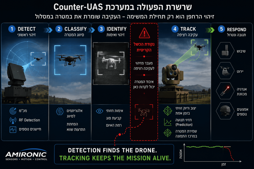
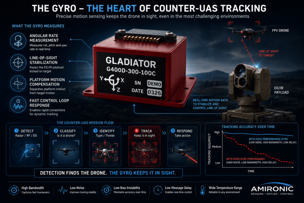
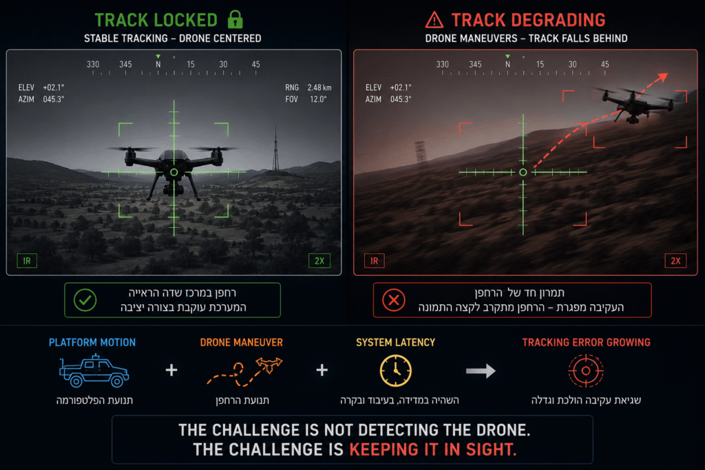
Figure 1 – Detecting the drone is only the first step. The real challenge for a Counter-UAS system is maintaining continuous target tracking while both the drone and the sensor platform are in motion.

What Really Causes a Counter-UAS System to Lose Track of a Drone?

When a Counter-UAS system loses track of a drone, it is easy to assume that the problem lies with the radar, the camera, or the computer vision algorithm.

In reality, the cause is often far more complex.

To keep a small drone centered within the field of view, the tracking system must continuously know two things:

  • Where the drone is moving.
  • Where the sensor itself is pointing.

Both of these are constantly changing.

The drone performs aggressive maneuvers, changes speed, altitude, and direction. At the same time, the Counter-UAS platform itself is also moving. An off-road vehicle bounces across rough terrain, a naval vessel is affected by waves, or a rotating turret rapidly slews to follow the target.

From the tracking system’s perspective, every one of these motions must be measured and compensated for in real time.

If the system cannot accurately determine how its own platform is moving, it may mistakenly interpret part of that motion as movement of the drone itself.

As a result, the tracking algorithm works with an incorrect estimate of the target’s position.

The control loop begins applying corrections in the wrong direction, the target drifts away from the center of the image, and in some cases the drone leaves the field of view entirely.

It is precisely at this stage, when the computer vision system attempts to maintain target lock, that the quality of the inertial measurements becomes one of the most critical factors in the entire tracking chain.


Why Is Tracking a Drone So Much More Difficult Than Tracking Other Targets?

Modern drones are fundamentally different from traditional aerial targets.

A manned aircraft or helicopter typically follows a relatively smooth flight path with well-defined dynamic limits.

An FPV drone or multirotor drone, however, can perform all of the following within fractions of a second:

  • Sharp turns
  • Near-instant stops
  • Rapid acceleration
  • Sudden altitude changes
  • Sideways movement (strafing)
  • Rapid yaw rotations

Each of these maneuvers requires the tracking system to respond almost immediately.

At the same time, the platform carrying the Counter-UAS system continues to move as well.

As a result, the tracking system is not solving a single tracking problem – it is solving two simultaneously.

It must continuously follow the drone’s motion while, at the same time, compensating for the motion of the platform carrying the sensors.

This is exactly why advanced tracking systems do not rely on the camera alone.

Instead, they combine optical measurements with inertial data, allowing the system to distinguish between target motion and sensor platform motion.

Figure 2 – While the radar and EO/IR camera are responsible for detecting the drone, the gyroscope provides the information needed to keep it centered in the image. Accurate measurement of platform motion is a fundamental requirement for stable target tracking and reliable Counter-UAS performance in dynamic environments.

The Gyroscope Doesn’t Look for the Drone – It Tells the System Where It Is Looking

When discussing Counter-UAS systems, most attention naturally focuses on the radar, the EO/IR camera, or the artificial intelligence algorithms.

That is understandable. These are the components responsible for detecting the drone, recognizing it, and assessing the level of threat.

However, for a system to maintain continuous tracking of a small, highly maneuverable drone, it must know not only where the target is, but also where its own sensor is pointing at every moment.

That is precisely the role of the gyroscope.

A gyroscope does not detect targets or process images. Instead, it continuously measures the platform’s angular rate about its three axes.

At first glance, this may appear to be a simple measurement. In reality, it is one of the most critical sources of information within the tracking loop.

Whenever the EO/IR system changes its pointing direction to follow a drone, the control computer must determine whether the apparent motion in the image is caused by the drone itself or by movement of the turret, vehicle, vessel, or other platform carrying the sensor.

Without accurate inertial information, distinguishing between these two sources of motion becomes extremely difficult.

As a result, the tracking system may begin applying unnecessary corrections, react too late, or even steer the line of sight in the wrong direction.

In highly dynamic environments, even small errors like these can accumulate rapidly, eventually allowing the drone to leave the field of view.


Not Every Gyroscope Performs Equally Well in Dynamic Tracking Applications

At first glance, every gyroscope performs the same basic function – measuring angular rate.

For a Counter-UAS system, however, the critical question is not whether the gyroscope measures motion, but how well it measures it.

Keeping a small drone centered within the image over an extended period requires a measurement and control chain capable of operating with both high accuracy and high responsiveness.

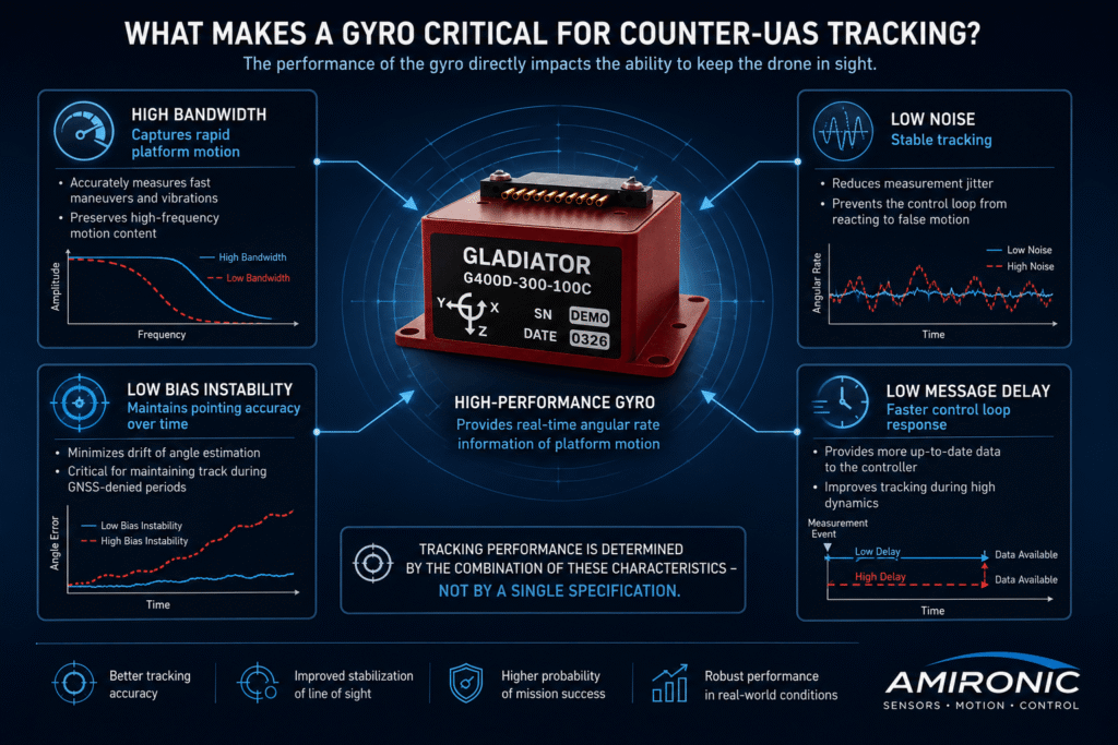
Several gyroscope characteristics directly influence the system’s ability to achieve this:

  • Bandwidth – Determines how accurately the sensor can capture rapid platform motion without losing dynamic information.
  • Noise – Directly affects measurement stability. Excessive noise can cause the control loop to react to motion that does not actually exist.
  • Bias Stability – Influences the ability to maintain an accurate estimate of orientation over time, particularly when no external reference is available for continuous correction.
  • Message Delay – Defines the time between the physical measurement and the moment the data becomes available to the control computer. Lower latency enables the control loop to operate using more current information.

Each of these parameters influences a different aspect of system performance.

In practice, however, they never operate independently.

A Counter-UAS system does not “feel” that one gyroscope has excellent bandwidth but excessive latency, or low noise but poor bias stability. It only experiences the combined result – whether it can keep the drone centered in the image throughout the mission.

Figure 3 – Counter-UAS tracking performance depends on the combination of multiple gyroscope characteristics. Each parameter influences a different part of the control loop, but only the right balance between them enables stable target tracking and long-term line-of-sight accuracy

Even the Best Gyroscope Doesn’t Work Alone

It is easy to assume that selecting a high-performance gyroscope will solve the tracking problem.

In reality, the situation is far more complex.

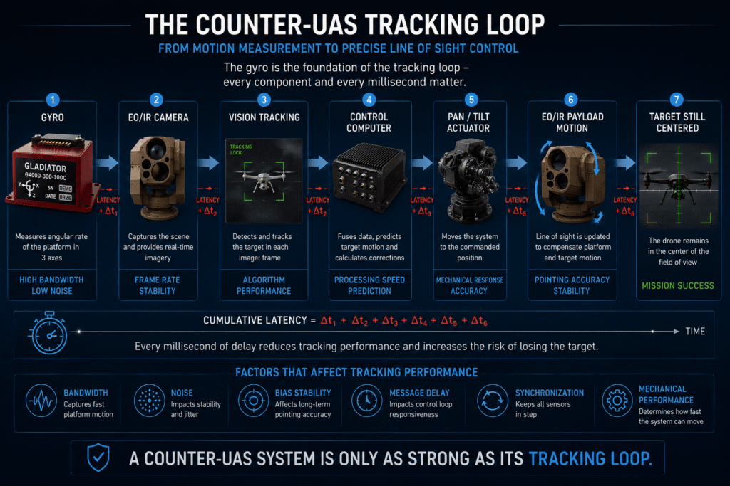
In a Counter-UAS system, the gyroscope is only one component within a much larger sensing, processing, and control chain. It provides essential information about platform motion, but before that information becomes a correction command for the turret or gimbal, it passes through several additional subsystems.

A typical tracking chain includes:

  • A gyroscope measuring the platform’s angular rate.
  • An EO/IR camera providing imagery of the target.
  • Angular encoders measuring the position of the gimbal axes.
  • A control computer performing sensor fusion and tracking calculations.
  • Motors and actuators driving the turret or gimbal.
  • Vision tracking algorithms identifying the drone’s position in every image frame.

Each of these components introduces a certain amount of uncertainty into the system.

Each also contributes its own latency.

As these effects accumulate, they can have a much greater impact on tracking performance than might initially be expected.

This is precisely why the performance of a Counter-UAS system cannot be evaluated by looking at a single specification on a gyroscope datasheet.

Ultimately, the system is judged by its ability to keep the drone centered in the image – not by the performance of any individual component.


Why Every Millisecond Matters

Counter-UAS systems operate as continuous closed-loop control systems.

During each control cycle, the system performs four fundamental tasks:

  • Measures platform motion.
  • Determines the drone’s position within the image.
  • Calculates the required correction.
  • Commands the EO/IR system to the new pointing position.

This process repeats dozens or even hundreds of times every second.

When the drone is flying a predictable trajectory, the control loop has relatively little difficulty maintaining accurate tracking.

However, the moment the drone performs a sudden maneuver, the entire system must react almost instantaneously.

Any additional delay – whether in sensing, processing, communication, or actuator response – increases the difference between where the drone actually is and where the system believes it is.

Eventually, that error may become large enough for the drone to drift toward the edge of the field of view.

If the maneuver continues, or the error continues to grow, the vision tracking system may lose the target entirely.

For this reason, in Counter-UAS systems, tracking is not only a matter of accuracy – it is also a matter of timing.


When Everything Works Properly, Nobody Notices

One of the most interesting characteristics of a well-designed tracking system is that, when it performs correctly, it is almost invisible to the operator.

The drone remains centered in the display.

The image appears stable.

Target motion is smooth and continuous.

It almost seems as though the system simply knows where to look.

Behind that stable image, however, a sophisticated combination of sensors, algorithms, and control loops is performing thousands of calculations every second to compensate for vibration, acceleration, and platform motion.

When one element in this chain fails to provide accurate or timely information, the consequences are not always immediately obvious.

The degradation may begin as a barely noticeable hesitation, progress into increasingly inaccurate tracking corrections, and, in highly dynamic scenarios, ultimately result in complete target loss.

This is exactly why Counter-UAS developers evaluate the performance of the entire tracking chain rather than focusing on any individual component. A successful system is defined not by the specifications of a single sensor, but by how effectively all of its components work together to maintain continuous target tracking.

Figure 4 – The tracking loop combines inertial measurements, EO/IR data, vision tracking algorithms, the control computer, and actuators. Each component contributes to overall system performance, but also introduces latency and uncertainty. The success of a Counter-UAS system depends not on a single component, but on the precise coordination of the entire tracking chain.

Why Tracking That Looks Perfect at the Beginning May Gradually Degrade

One of the most common mistakes is evaluating a Counter-UAS system based solely on the first few seconds of target tracking.

When the drone first enters the field of view, the EO/IR system is operating with fresh sensor data, the tracking algorithms have just acquired the target, and accumulated errors are still relatively small.

As the engagement continues, however, the system must perform thousands of cycles of measurement, estimation, and correction. Each new control cycle relies on the information generated by the previous one.

Unlike a simulation, a real system does not “reset” every second. Even very small errors in measurement, latency, or attitude estimation can gradually accumulate over time.

The result is not necessarily a sudden loss of performance, but a gradual process in which a system that appeared perfectly stable at the beginning of the engagement becomes progressively less accurate.

It is important to recognize that the rate of this degradation is not determined by the gyroscope alone. It is also influenced by the control loops, tracking algorithms, angular encoders, calibration quality, and the way all system components interact. Nevertheless, the quality of the inertial measurements remains one of the key factors determining whether the system can maintain stable target tracking throughout the engagement.

Tracking Timeline

🟢 0 Seconds
Target Acquired
Line of sight locked
Minimal accumulated error

⬇️

🟡 10 Seconds
Stable Tracking
Small measurement errors begin to accumulate

⬇️

🟠 30 Seconds
Increasing Challenge
Tracking accuracy depends increasingly on sensor quality and control loop performance

⬇️

🔴 60 Seconds
Higher Risk of Track Degradation
Without external corrections or target reacquisition, accumulated errors may gradually reduce tracking performance*

Time Since Tracking Started Typical System Behavior
0 seconds Target acquired, line of sight is stable, and accumulated error is negligible.
10 seconds Stable tracking continues, but small errors begin to accumulate.
30 seconds In dynamic scenarios, measurement quality and control loop performance become increasingly important for maintaining tracking accuracy.
60 seconds Without external corrections or target reacquisition, accumulated errors may have a greater impact on tracking performance, depending on the system architecture and operating conditions.

Small errors do not remain small. They accumulate over time.

The rate at which errors accumulate varies from one system to another and depends on factors such as system architecture, sensor performance, stabilization and tracking algorithms, control loop design, calibration quality, and operating conditions.

Case Study – Why Did the System Lose the Drone?

The Scenario

A Counter-UAS system is installed on a tactical vehicle protecting a strategic facility.

The system’s radar detects a small FPV drone at a range of approximately 2.5 km.

Within seconds, the EO/IR system acquires the target, the tracking algorithm locks on, and the drone remains centered in the image.

At this point, everything appears to be working perfectly.

A few seconds later, however, the drone performs a sharp turn, changes altitude, and accelerates toward a new heading.

At the same time, the vehicle carrying the Counter-UAS system continues traveling across rough terrain.

The tracking system must now compensate for two independent sources of motion occurring simultaneously:

  • The motion of the drone.
  • The motion of the sensor platform.

To keep the drone centered within the field of view, the control loop must continuously determine:

  • How the drone is moving.
  • How the platform itself is moving.
  • Where the camera is currently pointing.
  • What correction must be applied.

Any additional latency, measurement noise, or error in estimating platform motion can cause the required correction to be applied just slightly too late.

In a high-speed tracking system, slightly too late may already be too late.

The drone begins drifting toward the edge of the image.

If the maneuver continues, the vision tracking algorithm has progressively less reliable visual information available. Tracking quality degrades, and in some cases the target leaves the field of view entirely.

At that point, a system that successfully detected the drone may still lose it – not because the radar can no longer see the target, but because the tracking loop can no longer keep it centered within the image.


Why Does This Happen During Aggressive Maneuvers?

When a drone flies in a straight line at a constant speed, even a relatively simple tracking system can predict its motion with reasonable accuracy.

The more aggressively the drone maneuvers, however, the less the system can rely on prediction alone.

Every sudden change in direction requires the control loop to update its estimate of the system state, calculate a new correction, and reposition the EO/IR sensor within a very short period of time.

This is exactly where gyroscope performance becomes critical.

  • High bandwidth allows the sensor to capture rapid platform motion.
  • Low measurement noise helps maintain a stable control loop.
  • High bias stability reduces the accumulation of tracking errors over time.
  • Low message delay enables the control computer to make decisions using more up-to-date information.

None of these parameters alone guarantees successful target tracking.

Together, however, they enable the tracking loop to respond faster, more accurately, and with greater stability, even under highly dynamic operating conditions.

The G400D offers a compelling combination of high speed, low noise, excellent stability, compact size, and environmental robustness – characteristics that make it particularly well suited for high-speed tracking loops in Counter-UAS systems.

When the Specifications Meet the Mission: The G400D in Counter-UAS Tracking

In a Counter-UAS system, static accuracy alone is not enough. The gyroscope must rapidly detect platform angular motion, deliver that information to the control computer with minimal latency, and maintain low measurement noise even while operating under vibration, shock, and changing environmental conditions.

This is where the Gladiator Technologies G400D-300-100C stands out.

The sensor provides a ±300°/s measurement range, output rates of up to 10 kHz, bandwidths of up to 600 Hz, and a digital message delay of only 20 µs. It also offers a typical Angular Random Walk (ARW) of 0.0254°/√hr and a typical Bias In-Run of 0.8°/hr. All of this is packaged in a compact three-axis sensor weighing approximately 17 grams and occupying only 10.2 cm³.

The specifications presented here are typical values taken from the manufacturer’s preliminary datasheet.


Key Specifications of the G400D-300-100C

Parameter Specification Relevance to Counter-UAS Systems
Measurement Range ±300°/s Captures rapid EO/IR platform motion
Output Rate Up to 10 kHz Provides fresh motion data up to 10,000 times per second
External Sync Up to 10 kHz Enables precise synchronization with the control computer and other sensors
Bandwidth Up to 600 Hz Captures rapid motion and high-frequency vibration
Message Delay 20 µs Delivers data to the control loop with extremely low latency
Angular Random Walk 0.0254°/√hr Lower angular noise for cleaner motion estimation
Bias In-Run 0.8°/hr Excellent stability during continuous operation
Scale Factor Error 500 ppm Improves agreement between actual and measured motion
G-Sensitivity <0.01°/s/g Minimizes the influence of acceleration and vibration
Calibrated Temperature Range -50°C to +85°C Maintains calibrated performance over a wide environmental range
Operational Shock 1000 g, Half Sine, 0.5 ms Suitable for harsh mechanical environments
Operational Vibration 8 gRMS, 50 Hz-2 kHz Designed for vehicles, turrets, and airborne platforms
Weight Approximately 17 g Low impact on stabilized payloads
Volume 10.2 cm³ Easy integration into compact systems
MTBF @ 55°C >170,000 hours High reliability according to the manufacturer’s data

What Does a 20-Microsecond Delay Really Mean?

A 20 µs message delay may sound insignificant, but in a high-speed tracking loop every microsecond represents additional angular motion that occurs before the control computer receives the measurement.

Assume the platform is rotating at 300°/s, the full-scale measurement range of the sensor.

The angular error introduced by latency alone is:

300°/s × 0.000020 s = 0.006°

During those 20 microseconds, the platform rotates approximately 0.006° before the measurement reaches the control computer.

For illustration only, at a distance of 2.5 km, this corresponds to approximately 26 cm of line-of-sight displacement.

By comparison, a 60 µs message delay, as specified for the standard VELOX interface, would correspond to approximately 0.018°, or roughly 79 cm at the same distance.

Message Delay Angular Motion at 300°/s Approximate LOS Displacement at 2.5 km
20 µs 0.006° ~0.26 m
60 µs 0.018° ~0.79 m
1 ms 0.300° ~13.1 m

This example illustrates only the effect of communication latency. Overall system error also depends on the EO/IR sensor, tracking algorithms, control computer, actuators, encoders, and operating conditions.


Why 10 kHz and 600 Hz Are Not the Same Thing

These two specifications describe entirely different characteristics.

An output rate of 10 kHz means the sensor can deliver up to 10,000 measurements per second.

A bandwidth of 600 Hz defines the range of physical motion the sensor can accurately measure.

A high output rate allows the control computer to receive updated measurements more frequently, while high bandwidth enables the gyroscope to capture rapid platform dynamics.

For a Counter-UAS system, the combination of both is far more important than either specification alone.


Fast Is Not Enough – It Must Also Be Quiet

A fast gyroscope with excessive measurement noise can cause the control loop to respond to motion that does not actually exist.

The result may be unnecessary corrections, small line-of-sight oscillations, and degraded image stability.

The G400D-300-100C offers a typical ARW of 0.0254°/√hr, compared with 0.0424°/√hr for the 100B version and 0.0635°/√hr for the 100A version.

Its typical Bias In-Run also improves from 3°/hr in Version A and 1.5°/hr in Version B to 0.8°/hr in Version C.

Performance G400D-100C G400D-100B G400D-100A
Angular Random Walk 0.0254°/√hr 0.0424°/√hr 0.0635°/√hr
Bias In-Run 0.8°/hr 1.5°/hr 3°/hr
Bias Over Temperature 35°/hr 60°/hr 90°/hr
Scale Factor Error 500 ppm 600 ppm 750 ppm
G-Sensitivity <0.01°/s/g <0.01°/s/g <0.03°/s/g

The comparison within the product family shows that the 100C is not only the fastest interface option, but also delivers the strongest overall performance in terms of noise, bias stability, and scale factor accuracy.


The Real Advantage Is the Combination

Finding a sensor with one impressive specification is relatively easy.

Finding a three-axis gyroscope that combines all of the following is considerably more difficult:

  • Output rates up to 10 kHz
  • Bandwidth up to 600 Hz
  • 20 µs message delay
  • 0.0254°/√hr Angular Random Walk
  • 0.8°/hr Bias In-Run
  • Full calibration from -50°C to +85°C
  • Resistance to 1000 g shock and 8 gRMS vibration
  • Weight of approximately 17 grams
  • Digital interface with External Sync
  • Non-ITAR classification according to the manufacturer’s datasheet

For that reason, the engineering argument is not that the G400D is “the best gyroscope in the world” based on a single specification.

Rather, it offers a rare combination of high speed, low latency, low noise, excellent stability, environmental robustness, and compact size – exactly the characteristics required when a Counter-UAS system must not only detect a drone, but continue to keep it precisely centered while both the target and the sensor platform are moving.

In a Counter-UAS system, the best gyroscope is not necessarily the one with the lowest number in a single row of the datasheet. It is the one that provides the control loop with the right combination of fast, clean, stable, and precisely timed information.

That is where the G400D-300-100C stands out.

Conclusion

In a Counter-UAS system, detecting the drone is only the beginning of the mission.

The real challenge starts after detection, when the system must keep the target centered within the field of view while both the drone and the sensor platform continue to move.

As this article has shown, tracking performance is never determined by a single component. It depends on the combined performance of the inertial sensors, the EO/IR payload, the tracking algorithms, the control loops, the actuators, and, most importantly, how all of these elements work together as an integrated system.

For that reason, selecting a gyroscope should never be based on a single specification from a datasheet. Bandwidth, output rate, latency, measurement noise, long-term stability, and environmental robustness all contribute to the overall performance of the tracking loop.

In applications where every millisecond and every fraction of a degree can determine whether the drone remains centered or slips out of the field of view, gyroscope selection has a direct impact on mission performance.

Ultimately, the most effective Counter-UAS system is not the one that detects the drone first. It is the one that continues tracking it until the mission is complete.

If you are developing EO/IR systems, Counter-UAS solutions, or stabilized platforms, the Amironic engineering team can help you select the gyroscope that best matches your application’s performance requirements.

🧩 Further Reading and Deeper Insight

This article is part of a broader series exploring the engineering principles behind modern inertial sensing and motion stability in advanced control and navigation systems. For deeper technical context and system-level insights, you may also find the following articles valuable:

  • Bridging Control and Navigation: How Advanced MEMS IMUs Are Redefining System Performance
  • Gyro and IMU for Advanced Control Systems
  • The Silent Problem of Precision Systems – Why Gyros and IMUs Are Control Components, Not Just Sensors
  • Why External Sync is Critical in Gyro and IMU Systems
  • Stabilization, Tracking & Time Sync: The Foundation of Precise Line-of-Sight Control
  • Mission-Grade Stabilization in Dynamic EO/IR Systems: Why Bandwidth, Data Rate, and Phase Lag Define Gimbal Performance
  • Why Gladiator? What Truly Differentiates a High-End MEMS IMU Manufacturer
  • Common Misconceptions About MEMS Inertial Sensors
  • Bias Stability vs. Bias Instability: What really determines the performance of Gyro and IMU systems in stabilization, tracking, and navigation
  • Scale Factor in MEMS IMUs – The Error That Quietly Destroys Accuracy
  • The IMU Was Excellent. The Image Still Shook.
  • 2000Hz IMU? Before You Get Impressed, Understand Three Completely Different Numbers
  • SX3: Pushing MEMS Beyond Traditional Stabilization
  • Why a Smaller IMU Can Save Months of Development
  • Your Image Still Shakes Despite Choosing a Gyroscope with Excellent Bias Stability
  • Why Replacing an IMU Can Lead to Weeks of Recalibration
  • From IMU to INS: How a Tactical Navigation System Is Really Built
  • When GPS Is Lost, It’s Already Too Late to Choose an IMU

Frequently Asked Questions (FAQ)

Does a gyroscope detect the drone?

No. A gyroscope does not detect targets or “see” the drone. Its role is to measure the angular motion of the platform carrying the EO/IR system, allowing the control loop to distinguish between platform motion and target motion.


Why can a Counter-UAS system lose a drone even after detecting it?

Detection and tracking are two different stages of the engagement. After detection, the system must keep the drone centered within the field of view despite target maneuvers, platform motion, and latency throughout the control loop. As accumulated errors increase or system response becomes insufficient, tracking performance may degrade and the target can leave the field of view.


Is high bandwidth more important than a high output rate?

No. The two specifications complement each other. Bandwidth defines the range of angular motion the gyroscope can measure accurately, while output rate determines how frequently measurements are delivered to the control computer. High-performance tracking systems require both.


How important is message delay?

In high-speed tracking loops, even delays of a few tens of microseconds contribute to the overall system latency. The sooner measurement data reaches the control computer, the sooner corrective actions can be calculated and executed, particularly during aggressive maneuvers by the drone or the sensor platform.


Does Angular Random Walk (ARW) affect only measurement accuracy?

No. Excessive measurement noise can cause the control loop to react to motion that does not actually exist. The result may be unnecessary corrections, reduced line-of-sight stability, and degraded tracking performance.


Can a gyroscope be selected based on a single datasheet specification?

In most cases, no. Counter-UAS performance depends on a combination of characteristics, including bandwidth, output rate, message delay, measurement noise, long-term stability, calibration quality, and environmental robustness. The entire performance envelope should be evaluated against the application’s requirements.


Is overall Counter-UAS performance determined only by the gyroscope?

No. Although the gyroscope is a critical component of the tracking loop, overall performance also depends on the EO/IR sensors, tracking algorithms, control computer, actuators, encoders, and the way all of these components operate together as an integrated system.


How should a gyroscope be selected for a Counter-UAS system?

Gyroscope selection should be driven by mission requirements rather than by a single specification. Important considerations include measurement range, bandwidth, output rate, message delay, Angular Random Walk (ARW), bias stability, operating temperature range, environmental robustness, and compatibility with the system’s control architecture. The goal is not to choose the sensor with the most impressive individual specification, but the one that provides the best overall balance of performance for the intended application.


Glossary

Counter-UAS (Counter-Unmanned Aircraft System)

A system designed to detect, identify, track, and, in some cases, defeat unmanned aircraft. Counter-UAS systems typically integrate radar, RF sensors, EO/IR payloads, tracking algorithms, and response mechanisms.


UAS (Unmanned Aircraft System)

An unmanned aircraft system consisting not only of the aircraft itself, but also the ground control station, communication links, software, and command-and-control infrastructure.


EO/IR (Electro-Optical / Infrared)

An imaging system incorporating visible-light cameras, infrared cameras, or both. EO/IR systems are widely used for target detection, identification, tracking, and visual confirmation in day and night operations.


Line of Sight (LOS)

The precise direction in which the sensor or camera is pointing at any given moment. Maintaining a stable line of sight is fundamental to accurate target tracking.


Tracking

The process of continuously keeping a target centered within the field of view despite motion of either the target or the sensor platform.


Detection

The stage at which a target is first recognized by the system. Detection alone does not guarantee successful tracking.


Angular Rate

The rate at which the platform rotates, typically expressed in degrees per second (°/s). This is the physical quantity measured by a gyroscope.


Gyroscope

An inertial sensor that measures angular rate about one or more axes. In Counter-UAS applications, gyroscopes provide the motion information required for line-of-sight stabilization and compensation for platform movement.


Message Delay

The time between a measurement being taken by the sensor and that measurement becoming available to the control computer. Lower message delay enables faster control-loop response.


Bandwidth

The range of motion frequencies that the sensor can accurately measure. Higher bandwidth allows the gyroscope to respond effectively to rapid platform dynamics and vibration.


Angular Random Walk (ARW)

A measure of the gyroscope’s random noise. Lower ARW indicates cleaner, more stable measurements, particularly when angular rate is integrated over time.


Bias Stability

A measure of how consistently a gyroscope maintains its zero-rate output over time. Higher bias stability reduces long-term drift and helps maintain accurate attitude estimation and stable line-of-sight tracking during extended missions.

Tags: Gladiator_Technologies

Related Articles

When GPS Is Lost, It’s Already Too Late to Choose an IMU

21/07/2026amironicLTD

Why Replacing an IMU Can Lead to Weeks of Recalibration

12/07/2026amironicLTD

Stabilization, Tracking & Time Sync: The Foundation of Precise Line-of-Sight Control

22/02/2026amironicLTD

Recent Posts

  • Why Do Counter-UAS Systems Lose Track of a Drone Right After Detecting It?
  • Why Programming a Rotary Position Sensor to 360° Is Sometimes the First Design Mistake
  • Don’t Design a New Footswitch – Build It from a Modular Platform
  • When GPS Is Lost, It’s Already Too Late to Choose an IMU
  • USB Foot Pedals for Medical & Industrial Systems – Why the USB Connector Is Only Part of the Story

Categories

  • Air Switch
  • Circuit Breakers
  • Elapsed Time Indicator
  • Feedthrough
  • Footswitches
  • Gears & Transmission
  • Hour Meters
  • Infra Red Switches
  • INFRARED LAMPS
  • Low Noise Inertial MEMS
  • Mechanics
  • MEMS Gyroscope
  • MEMS Inertial
  • Microelectronics
  • Motors
  • Position Sensors
  • Power Supply
  • Pressure Sensors
  • Pressure Switch
  • Temperature Sensors
  • Tungsten and Molybdenum
  • Uncategorized
  • Vacuum Switches

Quick Contact

Fill out the form and our representatives will return to you

    Name (required)

    Email (required)

    Phone

    Message

    This site is protected by reCAPTCHA and the Google
    Privacy Policy and
    Terms of Service apply.

    Amironic Ltd.

    3 Rabinovich Street, Petah Tikva 4928144 , Israel. Tel: +972-3-9047744 E-mail: office@amironic.co.il
    Email
    Facebook
    Twitter
    LinkedIn
    YouTube
    Press on the ISO Certificate below for download
    ISO 9001:2015 Certification
    • MEMS Inertial
    • Circuit Breakers
    • Footswitches
    • Mechanical & Transmisions
    • Sensors
    • Motors
    • Electronics
    • Hand Control
    • Power Solutions

    News

    • Why Do Counter-UAS Systems Lose Track of a Drone Right After Detecting It?
    • Why Programming a Rotary Position Sensor to 360° Is Sometimes the First Design Mistake
    • Don’t Design a New Footswitch – Build It from a Modular Platform
    • When GPS Is Lost, It’s Already Too Late to Choose an IMU
    • USB Foot Pedals for Medical & Industrial Systems – Why the USB Connector Is Only Part of the Story
    About AmironicContactעברית
    © 2022 Amironic All rights reserved. All Trademarks are the property of their respective owners.
    • Increase Font
    • Decrease Font
    • Black & White
    • Inverse Colors
    • Highlight Links
    • Regular Font
    • Reset