Why Programming a Rotary Position Sensor to 360° Is Sometimes the First Design Mistake
A 360° rotary position sensor may seem like the safest possible choice.
It covers a full revolution, suits a wide range of applications, and gives designers the flexibility to accommodate future changes in mechanical travel. For this reason, many systems leave the sensor programmed for 360°, even though the mechanism itself only moves through 60°, 85°, or 120°.
At first glance, this appears to be the most flexible design approach.
In reality, it can be the first design mistake.
In many industrial systems, measurement quality is determined not only by the sensor itself, but also by how well it is matched to the application’s actual motion.
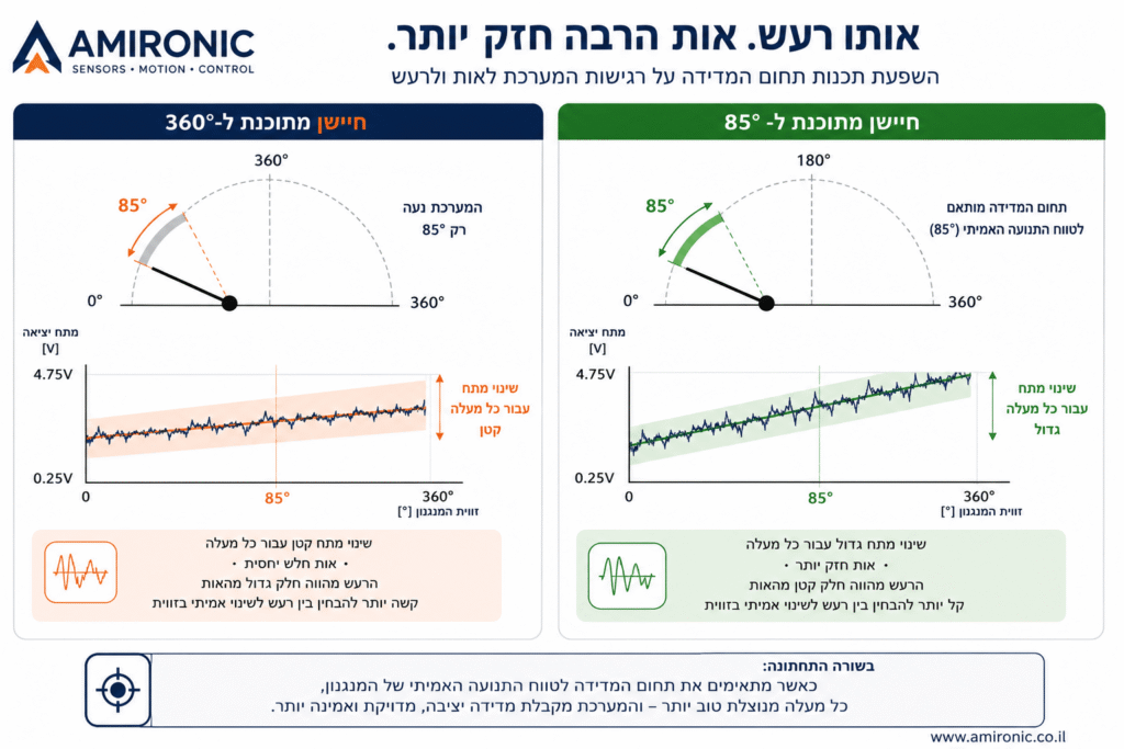
When the programmed measurement range is significantly larger than the mechanism’s real travel, only a small portion of the sensor’s electrical output span is actually used. The result can be lower effective sensitivity to angular changes, inefficient use of the controller’s input range, and greater difficulty distinguishing real motion from electrical noise, mechanical tolerances, and small signal variations.
The problem is not that the sensor lacks accuracy.
The problem is that the system is not taking full advantage of what the sensor can deliver.
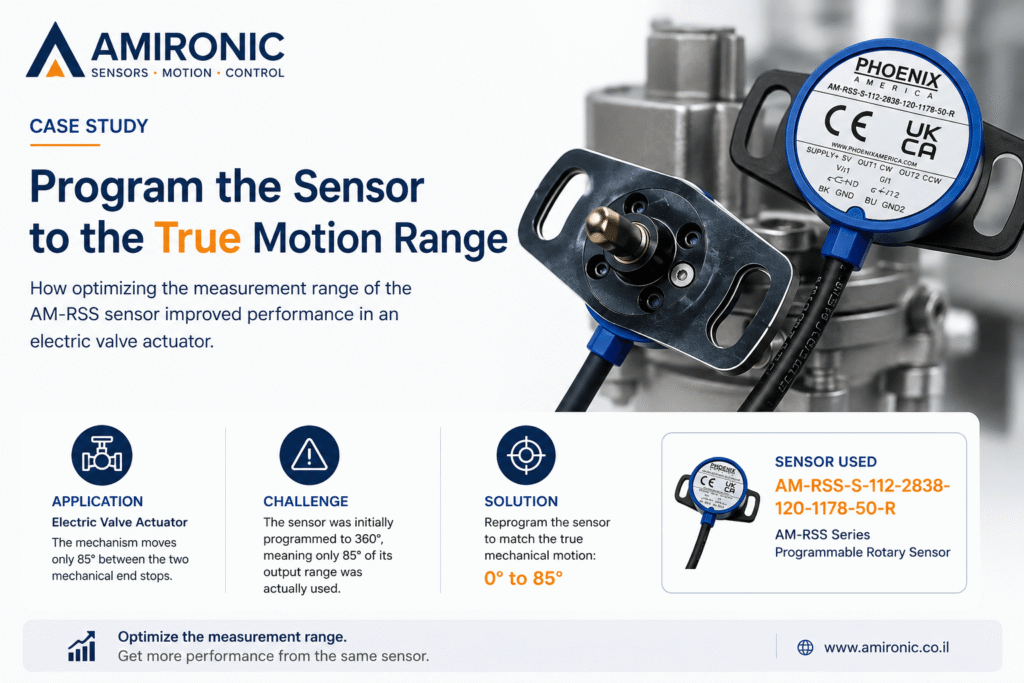
The AM-RSS rotary position sensor family, for example, allows its measurement range to be programmed anywhere between 30° and 360°, in 1° increments. Instead of forcing the mechanism to fit a standard 360° sensor, the sensor itself can be configured to match the mechanism’s actual range of motion.
That seemingly simple decision can significantly improve how effectively the entire control system uses the information provided by the sensor, without changing the mechanics, electronics, or control software.
The Mechanism Moves Only 85°. Why Measure 360°?
Imagine a mechanism that moves between two mechanical end stops with a total travel of 85°.
Typical examples include:
- An electric valve actuator
- A control lever
- A throttle mechanism
- A mechanical arm
- A rotary actuator
- A steering mechanism
- A shaft in an industrial machine
Mechanically, the system is never intended to complete a full revolution. It only operates within 85° of motion.
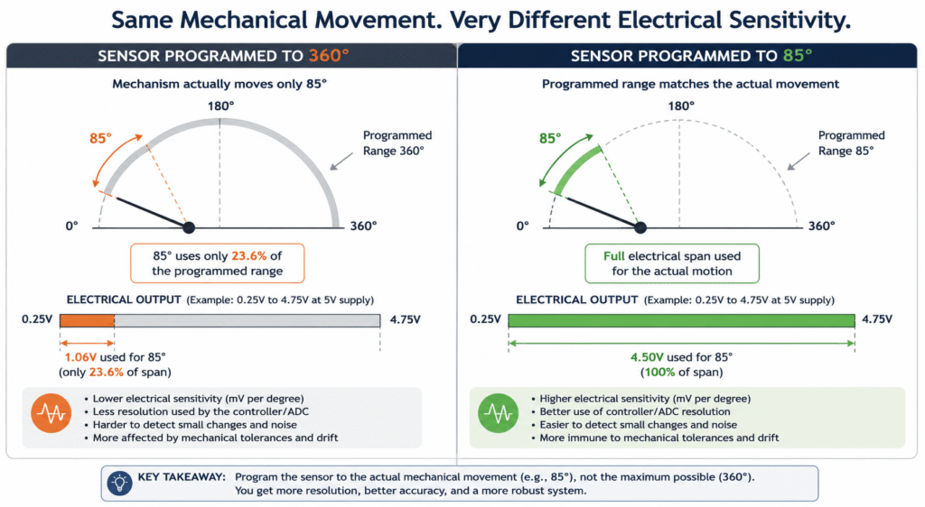
If the sensor is programmed for 360°, those 85° represent only 23.6% of its available measurement range.
In other words, more than three-quarters of the sensor’s measurement capability remains unused.
Consider a ratiometric analog output sensor. Suppose its output spans from 5% to 95% of the supply voltage. If the entire electrical output range is assigned to 360°, an 85° movement will use only a small fraction of the available signal.
If the sensor is instead programmed directly for 85°, the entire electrical output span is dedicated to the motion that actually matters.
This is not just a matter of numbers.
It is a matter of how much electrical information the controller receives for every degree of mechanical movement.
A Simple Example
Assume the sensor provides an analog output from 0.25 V to 4.75 V with a 5 V supply.
The usable output span is therefore:
4.5 V
Sensor Programmed for 360°
Each degree represents approximately:
4.5 V ÷ 360° = 12.5 mV/°
An 85° movement therefore produces:
85° × 12.5 mV = 1.06 V
This means the entire mechanism uses only 1.06 V of the available 4.5 V output span.
Sensor Programmed for 85°
Each degree now represents approximately:
4.5 V ÷ 85° = 52.9 mV/°
The same mechanical movement now utilizes the entire electrical output range.
The mechanics have not changed.
The sensor has not changed.
The controller has not changed.
Only the programmed measurement range has changed.
Yet the electrical sensitivity per degree is now more than four times higher.