flagעברית
flagEnglish
3 Rabinovich St., Petah-Tikva, Israel
+972 3 9047744
office@amironic.co.il
Facebook
Twitter
LinkedIn
YouTube
  • Products
    • MEMS Inertial
      • Gyros & Accels
      • IMU
      • Inertial Navigation
      • AHRS
    • Circuit Breakers
      • Airpax Circuit Breakers
      • Electronic Circuit Breakers
      • Aircraft Circuit Breakers
      • Thermal Circuit Breakers
      • Sealing Solutions & Guards
    • Footswitches
      • Pedals & Bellows
      • USB
      • Air Switches
      • Medical
      • Modular Bases System
      • Industrial
      • Foot Potentiometers
      • Wireless
    • Mechanical & Transmisions
      • Gears
      • Sealing Solutions
      • Gearboxes
      • Couplings
      • Shafts & Bearings
      • Fasteners
      • Mechanical & Springs
      • Linear Motion
      • Anti-Vibration
    • Sensors
      • Thermostats
      • Temperature
      • Position
      • Pressure
      • Speed
      • Level Sensor
      • Load Cells
      • Flex Sensors
      • Membrane Potentiometer
    • Motors
      • Geared DC
      • Brushless DC
      • Step Motors with Gearbox
      • Torque Motors & Brushless Servo
      • DC Motors
    • Electronics
      • Xenon & IR Lamps
      • Counters & Meters
      • Microelectronics Packaging
      • Waterproof Switches
      • Micro Switches
    • Hand Control
      • Operator Controls (JOYSTICK)
      • Electrical
      • Pneumatic (Medical)
      • USB Hand Control
      • Air Push Button
      • Pressure Switch
      • IR Switch
    • Power Solutions
      • Rugged & Military Power Supply
      • Input Power Protection
      • Sealed Military Power Adaptor
      • Triple Output Military Power Supply Series – up to 250 W
    • Materials
      • Molybdenum and Advanced Alloys (TZM, MOLA, HCT)
      • Tungsten (Wolfram) and Advanced Alloys – High-Performance Materials for Extreme Conditions
      • Materials for Gears
  • Shop
  • Companies
  • About Amironic
  • News
  • Contact
Product was added to your cart

Cart

waze

MIL-STD-1275 – Power Supplies and DC-DC Converters for Military Vehicles

Power Supply01/09/2026amironicLTD

Electronic systems installed in military vehicles are typically powered by an electrical system based on a nominal 28VDC supply. This power system may supply military computers, communication systems, command and control systems, sensors, displays, navigation systems, and other electronic equipment.

At first glance, selecting the power supply seems straightforward: if the system operates from 28VDC, a DC-DC Converter with an input range that includes this voltage, such as 18-36VDC, may appear to be suitable.

However, in a military vehicle, the fact that a converter can operate from 28VDC under normal conditions is not enough.

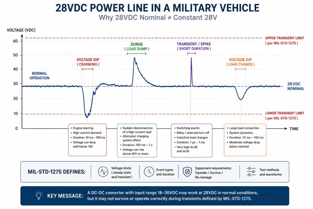
The vehicle electrical system is not an ideal DC source. During engine starting, switching loads on and off, alternator operation, load disconnection, and other electrical events, the voltage supplied to the equipment can differ significantly from the nominal voltage and may also be exposed to short-duration, extreme electrical events.

MIL-STD-1275 addresses this electrical environment and the 28VDC power characteristics that must be considered for equipment connected to a military vehicle electrical system.

What Is MIL-STD-1275?

MIL-STD-1275 is a U.S. military standard that defines the characteristics of 28VDC electrical power systems in military vehicles and the electrical environment at the interface between the vehicle power system and connected equipment.

The standard is particularly relevant when designing or selecting:

  • Military Power Supplies
  • Military DC-DC Converters
  • Computers and embedded systems installed in military vehicles
  • Communication and control systems
  • Electro-optical systems
  • Sensors and control units
  • Mission equipment powered directly from the vehicle electrical system

The objective is not simply to ensure that the equipment can accept 28VDC. Depending on the applicable requirements, the equipment must be able to operate, survive, or recover even when the power line is not providing a stable, ideal DC voltage.

28VDC Is a Nominal Voltage – Not the Required Converter Input Range

This is one of the most important points in understanding MIL-STD-1275.

When a system is specified as 28VDC, it does not mean that the connected equipment will always see exactly 28 volts.

The voltage may vary during normal operation, and electrical events can also occur that extend significantly beyond the normal operating range.

It is therefore important to distinguish between two different factors:

The operating input voltage range of the DC-DC Converter
For example, a converter specified for continuous operation from 18-36VDC.

The electrical environment in which the converter is installed
This includes not only the normal operating voltage but also Transients, Surges, Spikes, Voltage Drops, and other events that may appear on the power line.

A commercial converter with a datasheet specifying:

Input: 18-36VDC

may operate perfectly when powered by a stable 28VDC laboratory power supply.

However, this alone does not mean that it is suitable for direct connection to a military vehicle’s 28VDC electrical system.

It may require an additional input protection circuit, or it may be preferable to select a power supply or DC-DC converter specifically designed for the MIL-STD-1275 electrical environment.

What Can Happen on a Military Vehicle’s 28VDC Power Line?

A vehicle electrical system includes batteries, an alternator, switches, relays, motors, and many different types of electrical loads. A change in the operating state of one of these elements can affect the power line supplying the electronic equipment.

As a result, the equipment may be exposed to conditions including:

  • Voltage variations during normal operation
  • Voltage Dips
  • Surges
  • Transients
  • Short-duration voltage Spikes
  • Disturbances caused by load switching
  • Abnormal conditions associated with the vehicle’s power generation and energy storage system

The duration of an event can be just as important as its voltage amplitude.

A very short event with limited energy is not the same as an overvoltage condition that persists for a longer period. Protection design therefore cannot be based solely on the question, “What is the maximum voltage?” It must also consider the duration of the event, its energy, and the required response of the equipment.

This is exactly why an input range such as 18-36VDC tells only a small part of the story.

Figure 1: 28VDC Power Line in a Military Vehicle – Illustration showing that 28VDC is a nominal voltage only. In practice, the vehicle electrical system may be exposed to voltage dips, surges, and transients. Therefore, an 18-36VDC input range alone does not indicate compliance with MIL-STD-1275 requirements.

Why Is an 18-36VDC Input Range Not Enough?

When reviewing the specifications of a DC-DC converter, one of the first parameters to check is the Input Voltage Range.

For example:

Input Voltage: 18-36VDC

From a continuous operating voltage perspective, 28VDC falls well within this range. However, this specification typically describes the range over which the converter is designed to operate continuously and provide its specified performance.

It does not necessarily indicate what will happen when the input voltage temporarily exceeds or falls outside this range.

For example, it is important to check:

  • What is the maximum input voltage the converter can withstand without damage?
  • How does it respond to a Surge?
  • How does it respond to a short, fast Transient?
  • What happens when the input voltage falls below the minimum operating voltage?
  • Is Reverse Polarity Protection provided?
  • Does the converter automatically return to normal operation after an abnormal electrical event?

Two converters with the same 18-36VDC input range can behave very differently when connected to a military vehicle electrical system.

One may include a Front-End specifically designed for a military electrical environment, while the other may be intended for a controlled DC source and require external protection circuitry.

Therefore, Input Voltage Range is not a substitute for Transient Protection requirements.

Transient, Spike, and Surge – What Is the Difference?

The terms Transient, Spike, and Surge are sometimes used interchangeably, but from a power supply design perspective, it is important to understand that not every voltage disturbance is the same type of event.

Transient

A Transient is a temporary change in voltage caused by an event within the electrical system.

It may be positive or negative, extremely short or longer in duration, and accordingly, the amount of energy that the protection circuit must handle can vary significantly.

Spike

A Spike is typically a very short and fast event in which the voltage changes sharply.

Despite its short duration, a high voltage applied directly to the input of an unprotected device can cause a malfunction, Reset, or even damage to the input components.

Surge

A Surge is an overvoltage event that generally lasts significantly longer than a short Spike.

From the power supply’s perspective, this is an important distinction.

A protection component capable of absorbing a short Pulse may not necessarily be able to handle an elevated voltage that persists for a longer period. As the duration of the event increases, the amount of energy that must be managed, limited, or dissipated will generally increase as well.

Input protection should therefore be selected according to the voltage amplitude, event duration, and energy, rather than only according to the maximum voltage value.

What Is Required from the Power Supply During an Abnormal Event?

Another important point is that the term “compliance” does not necessarily mean that the system must continue operating perfectly and without interruption during every possible electrical event.

Depending on the requirement and the type of event, several different design objectives can be considered:

Operate – Continue Operating
The equipment continues to operate during the event while meeting the specified performance requirements.

Ride-Through – Continue Through the Event
The system is able to continue operating during a temporary disturbance or voltage drop, sometimes by using local energy storage.

Recover – Return to Normal Operation
The system may temporarily stop operating or perform a Reset, but once the input voltage returns to the normal range, it resumes normal operation.

Survive – No Permanent Damage
The equipment may not be required to operate during the event, but the event must not cause permanent damage.

This distinction is very important when defining system requirements.

For example, a critical mission computer may be required to continue operating during a specific voltage disturbance, while another unit may be permitted to Reset and recover after the event.

Therefore, before selecting a power supply or DC-DC Converter, it is important to understand not only what electrical event is expected, but also what the system is required to do during that event.

How Do You Protect a DC-DC Converter?

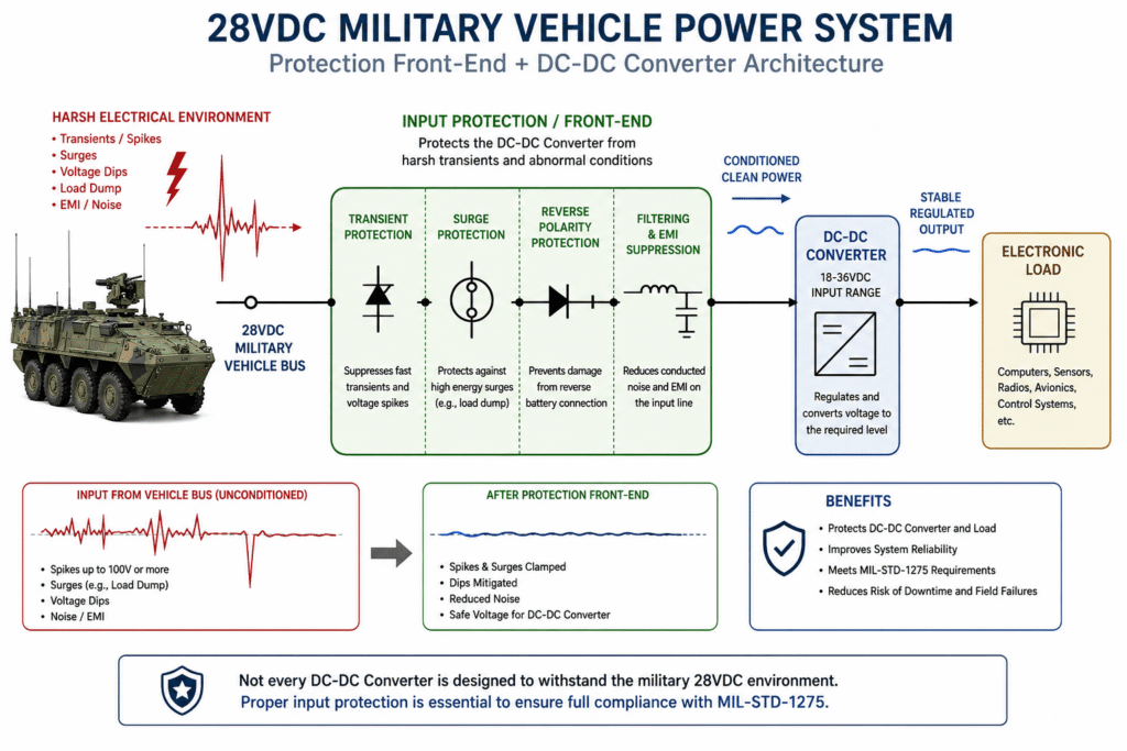
When the DC-DC converter itself is not designed to directly withstand all of the required input conditions, Input Protection / Front-End Protection can be added ahead of the converter.

Depending on the application and requirements, such a Front-End may include:

  • Overvoltage Protection
  • Transient Suppression
  • Reverse Polarity Protection
  • Inrush Current Limiting
  • Overcurrent and short-circuit protection
  • Filtering of disturbances on the power line
  • Voltage disconnection or limiting during a Surge
  • Energy storage components for Hold-Up or Ride-Through

The result is effectively a two-stage power architecture:

28VDC Vehicle Bus → Protection / Conditioning → DC-DC Converter → Electronic Load

The first stage handles the vehicle’s electrical environment and protects the converter.

The second stage performs the voltage conversion and supplies the electronic system with a stable voltage, such as 24VDC, 12VDC, 5VDC, or another voltage required by the load.

In some cases, this approach makes it possible to use a DC-DC converter with a relatively narrow continuous input range, provided that the Front-End ahead of it has been designed and tested to handle the system requirements.

However, it is important to emphasize:

Compliance of the protection circuit alone with a specific requirement does not demonstrate that the complete system complies with MIL-STD-1275.

Ultimately, the behavior of the input stage, power supply, and load should be evaluated as a complete system.

Figure 2: Input Protection Architecture for a 28VDC Military Vehicle System – The Front-End Protection circuit handles Transients, Surges, Reverse Polarity, and other disturbances before the voltage reaches the DC-DC Converter. This protects both the converter and the load and helps the system meet MIL-STD-1275 requirements.

Two Approaches to Power Supply Design for MIL-STD-1275

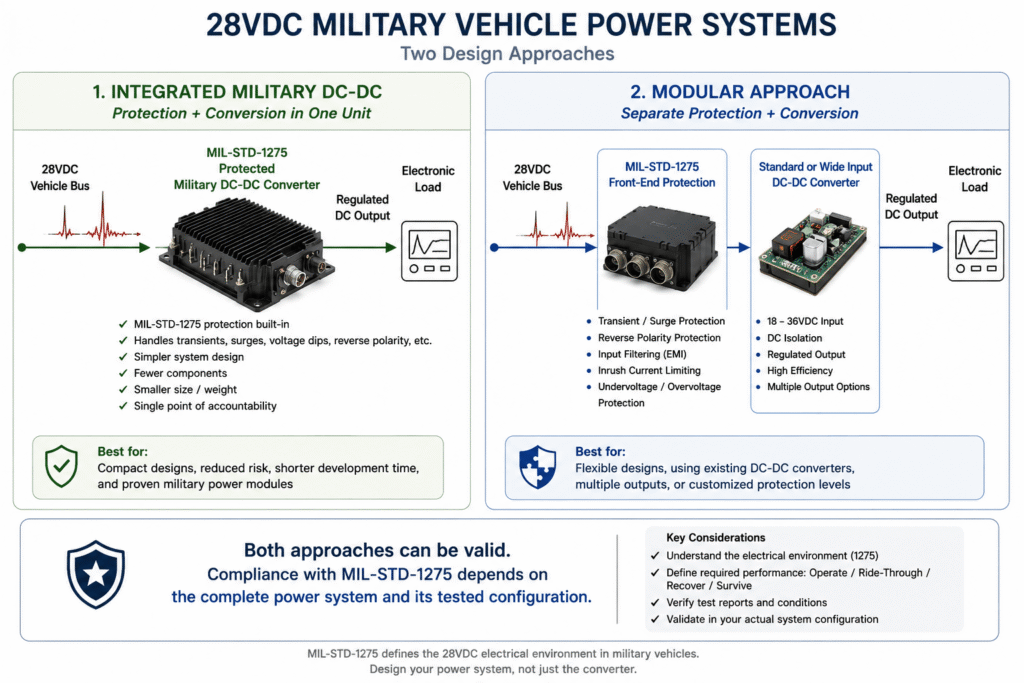
When an electronic system needs to be powered from a military vehicle’s 28VDC electrical system, there are two main approaches to designing the power chain.

Approach 1 – Power Supply or DC-DC Converter with Integrated Protection

In this approach, a Military DC-DC Converter or power supply is selected that has been specifically designed to handle the required input environment.

The input protection is part of the solution itself, so there is no need to design a separate external Front-End for each protection function.

The main advantage is simplicity at the system level. Instead of integrating several components and evaluating how they behave together, a power unit is used in which the protection and voltage conversion functions are already integrated.

This approach can be particularly suitable when:

  • A compact solution is required
  • Development time is limited
  • The design risk associated with the protection circuit needs to be reduced
  • There is a clear MIL-STD-1275 requirement
  • The manufacturer provides sufficient information regarding the tests performed on the product

However, even in this case, it is important to read the Datasheet carefully.

The presence of MIL-STD-1275 next to the product name is not sufficient by itself. It is important to understand exactly what was tested and under what conditions.

Approach 2 – Separate Front-End Protection and DC-DC Converter

The second approach separates the protection stage from the voltage conversion stage.

For example:

28VDC Vehicle Bus → MIL-STD-1275 Front-End → DC-DC Converter → Load

The Front-End handles abnormal input conditions and provides the converter with a voltage that remains within the range in which it can operate safely.

This approach gives the engineer greater flexibility.

The protection circuit and converter can be selected separately, matched to the required power level, and used to support multiple output voltages or different converters behind the same protection stage.

It can also be useful when the system already includes a DC-DC Converter that is suitable in terms of power, efficiency, and outputs, but cannot directly withstand the vehicle’s input electrical environment.

The disadvantage is that responsibility for ensuring system compatibility falls to a greater extent on the system designer.

It is necessary to verify that the Front-End and converter operate correctly together under all relevant input conditions.

What Does “MIL-STD-1275 Compliant” Really Mean?

This is one of the areas that should be examined carefully when comparing military power supplies.

Manufacturer specifications may use different statements, such as:

MIL-STD-1275 Compliant

Designed to Meet MIL-STD-1275

MIL-STD-1275 Compatible

Tested to MIL-STD-1275

These statements do not necessarily mean the same thing.

For example, a product designed with the standard’s requirements in mind is not necessarily a product that has undergone complete testing in the final configuration in which you intend to use it.

Therefore, when MIL-STD-1275 compliance is a project requirement, it is important to look beyond the marketing statement.

Questions worth asking the manufacturer include:

  • Which Revision of MIL-STD-1275 does the product address?
  • Which tests were actually performed?
  • Are Test Reports available?
  • Was the product itself tested, or was it tested as part of a system that included external protection components?
  • Is an additional Front-End required?
  • Under what load conditions was the testing performed?
  • Is the product required to continue operating during the event, or only to survive it?
  • Are there any limitations regarding input capacitance, wiring, or external components?

These details can be very significant.

A converter that meets the requirement only when used with a specific protection module ahead of it is not equivalent to a converter that can be connected directly to the 28VDC Vehicle Bus.

What About Voltage Drops During Engine Starting?

So far, we have focused mainly on events in which the input voltage increases, but the other side of the problem is equally important.

During engine starting, for example, the starter motor may draw a very high current from the battery. As a result, the vehicle electrical system voltage may drop for a certain period of time.

From the DC-DC Converter’s perspective, the question is not only whether it can survive the voltage drop.

The question is whether the system connected behind it needs to continue operating.

Assume that the converter operates over the following range:

18-36VDC

If the input voltage falls below 18V, the converter may enter Undervoltage Lockout – UVLO and stop providing output voltage.

When the input voltage returns to the operating range, the converter may resume normal operation.

From a survivability perspective, there may be no problem at all.

However, if the load is a mission computer that must not Restart every time the vehicle engine is started, this becomes a system-level problem.

Hold-Up and Ride-Through

When the load must remain powered during a temporary voltage drop, Ride-Through capability can be used.

One approach is to store energy in capacitors or other energy storage components, allowing the load to continue receiving power from the local energy storage while the input voltage is too low.

The required Ride-Through duration depends on the load and the duration of the voltage event.

The higher the load power and the longer the required Ride-Through time, the more stored energy is required.

Therefore, Hold-Up is not simply “another protection feature” that can be added without affecting the design. It can influence:

  • Capacitor size
  • Volume and weight
  • Inrush Current
  • Heat dissipation
  • Cost
  • System behavior during power-up and power-down

This is a good example of why meeting the requirements of a 28VDC system is not simply a matter of selecting a DC-DC Converter with a wide input voltage range.

What About Reverse Polarity?

Systems connected to a battery or DC power network should also consider the possibility of Reverse Polarity.

Applying the input voltage with reversed polarity can cause immediate damage to input components if the system is not protected.

Protection can be implemented in several ways, ranging from a simple diode to MOSFET-based solutions that provide lower conduction losses.

In high-power systems, this difference can be significant.

For example, the voltage drop across a diode carrying a high current creates power loss and heat. Therefore, a solution suitable for a unit consuming only a few watts may not necessarily be the right solution for a power supply rated at hundreds of watts.

Here too, the complete system must be considered rather than only the nominal input voltage.

Figure 3: Two Approaches to Military Vehicle Power System Design – A military DC-DC Converter with integrated MIL-STD-1275 protection can be used, or a separate Front-End Protection stage can be installed ahead of the DC-DC Converter. In both approaches, the complete system and the actual tested configuration should be evaluated.

How to Select a Power Supply or DC-DC Converter for a Military 28VDC System

Selecting a power supply for a system installed in a military vehicle should begin with the system requirements, not simply with the required wattage or output voltage.

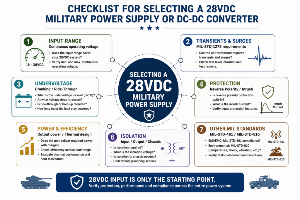
When a solution suitable for the MIL-STD-1275 environment is required, several key factors should be evaluated.

1. Continuous Input Voltage Range

First, verify that the converter can operate over the continuous input voltage range required by the system.

For example, an input range of:

18-36VDC

may be suitable for a 28VDC system in terms of continuous operation.

However, as we have seen, this is only the starting point.

The converter’s behavior outside its normal operating range must be evaluated separately.

2. Transient and Surge Protection

It is important to determine whether the product can directly withstand the relevant electrical events or whether Front-End Protection is required ahead of it.

A distinction should be made between:

Operating Input Voltage – the range over which the converter operates continuously.

Absolute Maximum Input Voltage – the voltage that must not be exceeded in order to prevent damage.

Transient Withstand – the ability to withstand a defined voltage excursion for a specified period of time.

These are three different specifications.

A converter may, for example, operate continuously up to a certain voltage while being able to withstand a higher voltage for only a short period of time.

Therefore, a specification such as “Maximum Input Voltage” without information about duration and test conditions is not always sufficient to determine suitability.

3. Behavior During Undervoltage

It is important to determine what happens when the input voltage drops.

Key questions include:

  • At what voltage does the converter stop operating?
  • Does it include UVLO – Undervoltage Lockout?
  • At what voltage does it resume operation?
  • Is there Hysteresis to prevent repeated switching on and off around the threshold?
  • Does the output remain stable until the shutdown point?
  • Can the system connected to the converter tolerate a Reset?

If Ride-Through is required, it is also necessary to determine how much energy is needed to keep the load operating during the voltage drop.

4. Reverse Polarity Protection

It should be verified whether Reverse Polarity Protection is integrated into the product or must be provided externally.

Especially in systems connected directly to a battery or the vehicle electrical network, this is a feature that should not be assumed unless it is explicitly stated in the specification.

5. Inrush Current

A power supply may contain significant input capacitance.

When connected to 28VDC, these capacitors temporarily appear as a low-impedance load and may result in a high Inrush Current.

This current can affect:

  • Circuit breakers
  • Fuses
  • Connectors
  • Relays
  • Wiring
  • Power switches
  • The number of units powered up simultaneously

When large capacitance is added for Hold-Up or Ride-Through, Inrush Current becomes even more important.

A proper design must therefore consider not only the energy supplied by the capacitors after they are charged, but also how they are charged.

6. Power and Efficiency

Once input compatibility has been established, the required output power must of course be selected.

For example, a system may require:

  • 50W
  • 100W
  • 150W
  • 300W
  • 500W
  • Or higher power

It is generally advisable not to design a system in which the power supply continuously operates at the limit of its capability without an appropriate Margin.

Efficiency is also particularly important in a sealed or enclosed military system.

For example, at an output power of 300W, the difference between 85% and 95% efficiency is significant in terms of the heat that must be dissipated from the enclosure.

The more compact and sealed the system, the more important thermal management becomes in the power supply design.

7. Isolation

Some systems require Galvanic Isolation between the input and output.

It is therefore important to check:

  • Is the converter Isolated or Non-Isolated?
  • What is the isolation voltage?
  • Is isolation required only between Input and Output, or also with respect to the chassis?
  • How are Ground and Chassis defined in the system?

This is not only a voltage-related consideration. It can also affect Ground Loops, safety, EMI, and the behavior of the complete system.

MIL-STD-1275 Is Not the Only Standard to Consider

Even if the power supply meets the electrical requirements of a 28VDC system, this does not automatically mean that it meets all the requirements of the military project.

Many systems have additional requirements.

MIL-STD-461 – EMI/EMC

MIL-STD-461 addresses requirements related to electromagnetic interference and compatibility – EMI/EMC.

A switching power supply is not only a consumer of electrical energy. It can also generate electrical interference.

In a military system, it may therefore be important to consider both the power supply’s immunity to interference and the amount of interference it conducts back onto the power line or radiates into the surrounding environment.

It is particularly important not to confuse these two areas:

MIL-STD-1275 addresses the vehicle’s 28VDC electrical environment.

MIL-STD-461 addresses EMI/EMC requirements.

A product suitable for one is not necessarily suitable for the other.

MIL-STD-810 – Environmental Conditions

A power supply installed in a military vehicle may also need to withstand harsh environmental conditions such as:

  • High and low temperatures
  • Vibration
  • Shock
  • Humidity
  • Dust
  • Altitude conditions
  • Additional environmental conditions depending on the application

These requirements are generally associated with MIL-STD-810 and the specific requirements of the project.

Here too, it is important to determine which tests were actually performed rather than relying solely on general terms such as “Rugged” or “Military Grade.”

A Common Mistake: “It Has a 28VDC Input, So It Is Suitable for the Vehicle”

This is perhaps one of the most common mistakes when selecting a power supply for a military vehicle system.

For example, a Datasheet may specify:

Input: 18-36VDC
Output: 12VDC / 150W
Operating Temperature: -40°C to +85°C

On paper, these specifications look excellent.

However, several important questions remain unanswered:

What happens during a Transient?

What happens during a Surge?

Is the converter protected against Reverse Polarity?

What happens during engine starting and a voltage drop?

Is an external Front-End required?

Does the product meet MIL-STD-1275 requirements, and if so, under what conditions?

Are there also MIL-STD-461 and MIL-STD-810 requirements?

Therefore, the statement:

“The converter accepts 28VDC”

is not equivalent to:

“The converter is suitable for connection to a military vehicle’s 28VDC electrical system.”

The difference between these two statements is essentially at the heart of MIL-STD-1275.

Figure 4: Key Considerations When Selecting a Power Supply or DC-DC Converter for a Military 28VDC System – In addition to the input voltage range, it is important to evaluate Transient and Surge withstand capability, behavior during voltage drops, input protection, power and efficiency, isolation, and additional requirements such as MIL-STD-461 and MIL-STD-810.

Frequently Asked Questions – FAQ About MIL-STD-1275 and Military Vehicle Power Supplies

What Is MIL-STD-1275?

MIL-STD-1275 is a U.S. military standard that addresses the characteristics of 28VDC electrical power systems in military vehicles and the electrical environment to which connected equipment is exposed.

The standard is particularly important when designing and selecting power supplies, DC-DC Converters, and electronic equipment powered from the vehicle electrical system.

Does a 28VDC System Always Supply 28 Volts?

No.

28VDC is a nominal voltage. In practice, the voltage can vary depending on the operating condition of the electrical system, and events such as Voltage Dips, Surges, and Transients may also occur.

Therefore, the vehicle electrical system should not be treated as a stable 28VDC laboratory power source.

Is an 18-36VDC Converter Suitable for a Military 28VDC System?

Not necessarily.

An 18-36VDC input range indicates that the converter can operate continuously at 28VDC, but it does not demonstrate that it can withstand all of the input conditions required in a military vehicle electrical system.

Transient and Surge withstand capability, behavior during Undervoltage, Reverse Polarity Protection, and other system requirements should be evaluated separately.

What Is the Difference Between Input Voltage Range and Transient Withstand?

Input Voltage Range generally refers to the voltage range over which the converter is designed to operate continuously.

Transient Withstand describes the converter’s ability to withstand a voltage event outside its normal operating range for a specified duration and under defined conditions.

A converter may be designed for continuous operation up to a certain voltage while being capable of surviving a higher voltage for a short period of time.

Therefore, both specifications should be evaluated separately.

Is a Special Military DC-DC Converter Always Required?

Not always.

A converter with the required protection functions integrated into the unit can be used, but it is also possible to design a system in which separate MIL-STD-1275 Front-End Protection protects a DC-DC Converter installed downstream.

The choice depends on power, size, weight, cost, development time, project requirements, and the level of flexibility required.

In either case, suitability should be evaluated at the complete system level.

What Is a MIL-STD-1275 Front-End?

A Front-End is a stage installed between the vehicle electrical system and the DC-DC Converter or electronic equipment.

Depending on the design, it may provide functions such as Transient Suppression, Surge Protection, Reverse Polarity Protection, Inrush Current Limiting, and filtering.

Its purpose is to protect the downstream electronics and condition the input voltage so that the converter can operate safely.

Does MIL-STD-1275 Also Cover EMI/EMC?

MIL-STD-1275 focuses on the vehicle’s 28VDC power environment.

Military EMI/EMC requirements are generally addressed by MIL-STD-461 and the applicable project requirements.

A power supply may therefore be required to meet both MIL-STD-1275 and MIL-STD-461 requirements.

What Is the Relationship Between MIL-STD-1275 and MIL-STD-810?

MIL-STD-1275 addresses the electrical environment of a vehicle’s 28VDC power system.

MIL-STD-810 addresses test methods for environmental conditions such as temperature, vibration, shock, humidity, and other conditions.

A power supply intended for a military vehicle may need to address both standards, but each standard covers a different aspect of the system.

What Happens During Vehicle Engine Starting?

During engine starting, a significant load may be placed on the electrical system, causing a temporary voltage drop.

If the voltage falls below the operating range of the DC-DC Converter, the converter may stop supplying output voltage until the input voltage recovers.

If the system is required to continue operating during the event, an appropriate Ride-Through or Hold-Up solution may be required.

What Should You Ask a Manufacturer That Claims MIL-STD-1275 Compliance?

When compliance with the standard is a project requirement, it is important to understand exactly what the manufacturer’s statement represents.

Among other things, it is recommended to verify which revision of the standard the manufacturer refers to, which tests were performed, under what conditions they were performed, whether Test Reports are available, and whether external components are required to achieve the stated level of protection.

Summary

Selecting a power supply or Military DC-DC Converter for a military vehicle involves more than simply matching the input voltage to 28VDC.

The vehicle electrical system is a dynamic environment in which voltage variations, Voltage Dips, Surges, Transients, and other events may occur that are not present when testing a converter with a stable laboratory power supply.

Therefore, a converter with an 18-36VDC input range is not necessarily suitable for direct connection to a military 28VDC electrical system.

The complete power chain should be evaluated:

28VDC Vehicle Bus → Input Protection → DC-DC Conversion → Electronic Load

In some systems, the protection functions are integrated into the power supply. In others, it may be more appropriate to use separate Front-End Protection followed by a DC-DC Converter.

In both cases, the important question is not simply:

“Does the converter operate from 28VDC?”

but rather:

“How does the complete power system behave under the electrical conditions it is expected to encounter in the vehicle?”

This is the key distinction between a standard DC-DC Converter and a power solution truly designed for the MIL-STD-1275 environment.

Need a Power Supply or DC-DC Converter for a Military 28VDC System?

When selecting a power solution for a military vehicle, it is important to define the input voltage, output voltages, power requirements, isolation requirements, environmental conditions, and applicable military standards in advance.

Amironic supplies power solutions and DC-DC Converters for military and defense applications and can assist in evaluating the requirements and selecting a suitable solution for the system.

When submitting an inquiry, it is recommended to provide as much of the following information as possible:

  • Input voltage and required input voltage range
  • Output voltage or voltages
  • Required power
  • MIL-STD-1275 requirements
  • MIL-STD-461 and MIL-STD-810 requirements, if applicable
  • Isolation requirements
  • Operating temperature
  • Size and weight limitations
  • Required quantity

The more completely the requirements are defined, the more accurately the suitability of the power supply or DC-DC Converter can be evaluated for the application.

Glossary – MIL-STD-1275 and 28VDC Systems

28VDC Vehicle Bus
The vehicle electrical power system with a nominal voltage of 28VDC. The actual voltage is not necessarily a constant 28V and may vary depending on operating conditions and events within the electrical system.

MIL-STD-1275
A U.S. military standard that addresses the characteristics of 28VDC electrical power systems in military vehicles and the voltage conditions to which connected equipment is exposed.

DC-DC Converter
A power converter that receives a DC voltage at its input and provides a different DC voltage at its output. For example, converting a 28VDC supply to 12VDC or 5VDC.

Military DC-DC Converter
A DC-DC Converter designed for military applications. Depending on the product and application, it may be designed to withstand abnormal voltage conditions, extreme temperatures, vibration, shock, and EMI/EMC requirements.

Input Voltage Range
The input voltage range over which the converter is designed to operate continuously. For example, 18-36VDC.

Transient
A temporary event in which the input voltage deviates from its normal condition. A Transient may be positive or negative and may vary in duration and energy.

Voltage Spike
A short, fast voltage excursion that can reach the equipment’s input components and cause a malfunction or damage if adequate protection is not provided.

Surge
An increase in voltage that generally lasts significantly longer than a short Spike and may therefore require the system to handle a higher amount of energy.

Voltage Dip / Undervoltage
A temporary reduction in input voltage below its normal level. Such an event may occur, for example, during vehicle engine starting or when a significant load is connected.

UVLO – Undervoltage Lockout
A protection mechanism that stops converter operation when the input voltage falls below a defined threshold and allows the converter to resume operation when the voltage recovers.

Front-End Protection
A protection stage installed between the vehicle electrical system and the DC-DC Converter. It may provide protection against Transients, Surges, Reverse Polarity, Inrush Current, and other disturbances.

Transient Suppression
The limiting or suppression of transient voltage events before they reach sensitive components within the power supply or electronic system.

Reverse Polarity Protection
Protection against applying the input voltage with reversed polarity.

Inrush Current
A high, short-duration current that may occur when the power supply is first connected to the input voltage, among other reasons due to charging of the input capacitors.

Ride-Through
The ability of the system to continue operating during a voltage disturbance or temporary voltage drop.

Hold-Up Time
The amount of time a power supply or system can continue supplying energy to the load after the input voltage drops or is interrupted.

Galvanic Isolation
Electrical separation between the power supply input and output, with no direct conductive connection between them.

MIL-STD-461
A military standard covering EMI/EMC requirements and test methods for equipment and systems.

MIL-STD-810
A military standard that includes test methods for environmental conditions such as temperature, vibration, shock, humidity, and other conditions.

Tags: GilGal

Related Articles

DC/DC Converter for MIL-STD-1275F: What a 24V→12V Power Supply That Truly Survives “Electrical Hell” Looks Like

02/02/2026amironicLTD

⚙️ Rugged & Military Power Supply Solutions

30/10/2025amironicLTD

Direct Current Adapter – Introducing the GIL‑75206‑24

30/07/2025amironicLTD

Recent Posts

  • MIL-STD-1275 – Power Supplies and DC-DC Converters for Military Vehicles
  • Military Power Supplies and DC-DC Converters – A Guide to MIL-STD Standards
  • How Do You Know If a Liquid Cooling System Is Really Working? Pressure and Temperature Tell the Story
  • Tactical Grade IMU: What Happens When the Mission Stops Behaving Like the Lab?
  • Why Run Electricity to the Button When Herga Can Switch It with Air?

Categories

  • Air Switch
  • Circuit Breakers
  • Elapsed Time Indicator
  • Feedthrough
  • Footswitches
  • Gears & Transmission
  • Hour Meters
  • Infra Red Switches
  • INFRARED LAMPS
  • Low Noise Inertial MEMS
  • Mechanics
  • MEMS Gyroscope
  • MEMS Inertial
  • Microelectronics
  • Motors
  • Position Sensors
  • Power Supply
  • Pressure Sensors
  • Pressure Switch
  • Temperature Sensors
  • Tungsten and Molybdenum
  • Uncategorized
  • Vacuum Switches

Quick Contact

Fill out the form and our representatives will return to you

    Name (required)

    Email (required)

    Phone

    Message

    This site is protected by reCAPTCHA and the Google
    Privacy Policy and
    Terms of Service apply.

    Amironic Ltd.

    3 Rabinovich Street, Petah Tikva 4928144 , Israel. Tel: +972-3-9047744 E-mail: office@amironic.co.il
    Email
    Facebook
    Twitter
    LinkedIn
    YouTube
    Press on the ISO Certificate below for download
    ISO 9001:2015 Certification
    • MEMS Inertial
    • Circuit Breakers
    • Footswitches
    • Mechanical & Transmisions
    • Sensors
    • Motors
    • Electronics
    • Hand Control
    • Power Solutions

    News

    • MIL-STD-1275 – Power Supplies and DC-DC Converters for Military Vehicles
    • Military Power Supplies and DC-DC Converters – A Guide to MIL-STD Standards
    • How Do You Know If a Liquid Cooling System Is Really Working? Pressure and Temperature Tell the Story
    • Tactical Grade IMU: What Happens When the Mission Stops Behaving Like the Lab?
    • Why Run Electricity to the Button When Herga Can Switch It with Air?
    About AmironicContactעברית
    © 2022 Amironic All rights reserved. All Trademarks are the property of their respective owners.
    • Increase Font
    • Decrease Font
    • Black & White
    • Inverse Colors
    • Highlight Links
    • Regular Font
    • Reset