flagעברית
flagEnglish
3 Rabinovich St., Petah-Tikva, Israel
+972 3 9047744
office@amironic.co.il
Facebook
Twitter
LinkedIn
YouTube
  • Products
    • MEMS Inertial
      • Gyros & Accels
      • IMU
      • Inertial Navigation
      • AHRS
    • Circuit Breakers
      • Airpax Circuit Breakers
      • Electronic Circuit Breakers
      • Aircraft Circuit Breakers
      • Thermal Circuit Breakers
      • Sealing Solutions & Guards
    • Footswitches
      • Pedals & Bellows
      • USB
      • Air Switches
      • Medical
      • Modular Bases System
      • Industrial
      • Foot Potentiometers
      • Wireless
    • Mechanical & Transmisions
      • Gears
      • Sealing Solutions
      • Gearboxes
      • Couplings
      • Shafts & Bearings
      • Fasteners
      • Mechanical & Springs
      • Linear Motion
      • Anti-Vibration
    • Sensors
      • Thermostats
      • Temperature
      • Position
      • Pressure
      • Speed
      • Level Sensor
      • Load Cells
      • Flex Sensors
      • Membrane Potentiometer
    • Motors
      • Geared DC
      • Brushless DC
      • Step Motors with Gearbox
      • Torque Motors & Brushless Servo
      • DC Motors
    • Electronics
      • Xenon & IR Lamps
      • Counters & Meters
      • Microelectronics Packaging
      • Waterproof Switches
      • Micro Switches
    • Hand Control
      • Operator Controls (JOYSTICK)
      • Electrical
      • Pneumatic (Medical)
      • USB Hand Control
      • Air Push Button
      • Pressure Switch
      • IR Switch
    • Power Solutions
      • Rugged & Military Power Supply
      • Input Power Protection
      • Sealed Military Power Adaptor
      • Triple Output Military Power Supply Series – up to 250 W
    • Materials
      • Molybdenum and Advanced Alloys (TZM, MOLA, HCT)
      • Tungsten (Wolfram) and Advanced Alloys – High-Performance Materials for Extreme Conditions
      • Materials for Gears
  • Shop
  • Companies
  • About Amironic
  • News
  • Contact
Product was added to your cart

Cart

waze

Tactical Grade IMU: What Happens When the Mission Stops Behaving Like the Lab?

MEMS Gyroscope, MEMS Inertial19/08/2026amironicLTD

Tactical Grade IMU: What Happens When the Mission Stops Behaving Like the Lab?

On the lab bench, everything looks perfect.

GNSS is available. The temperature is stable. Vibration is controlled. The power supply is clean. The IMU delivers data at a steady rate, and the system knows where it is and which way it is pointing at any given moment.

But an operational mission is not a lab bench.

Imagine an unmanned platform several minutes into its mission.

It begins to maneuver. Motor RPM changes, and the vibration spectrum changes with it. The temperature inside the system rises. At the same time, GNSS reception begins to degrade.

For a moment, everything still appears normal.

There is no FAULT message.

The GNSS continues to provide position data.

The Tactical IMU continues to output acceleration and angular rate measurements.

The mission computer continues to receive numbers.

But now a much more important question emerges:

Not what data did we receive – but which data can we still trust?

This is exactly where the difference begins to emerge between an IMU that looks excellent on a datasheet and a Tactical Grade IMU selected as part of a system that is expected to keep performing when conditions are no longer ideal.


Tactical Grade Is Not Tested When Everything Works

Comparing two IMUs under laboratory conditions is relatively easy.

Open two datasheets and compare:

  • Bias
  • Bias Instability
  • Angle Random Walk
  • Scale Factor
  • Bandwidth
  • Data Rate
  • Operating Temperature
  • Shock
  • Vibration

All of these parameters matter.

But an operational system does not encounter each parameter separately.

It encounters them together.

Temperature changes while the platform is vibrating.

The vibration environment changes while the vehicle is maneuvering.

GNSS may become unavailable precisely when the system needs reliable inertial information the most.

And sometimes the sensor continues to provide measurements that look completely reasonable even as the quality of the overall solution has already begun to degrade.

This suggests a slightly different way of thinking about the term Tactical Grade:

A Tactical Grade IMU should not be judged only by the accuracy it can achieve under favorable conditions, but by the system’s ability to continue obtaining useful and predictable inertial information from it as mission conditions change.
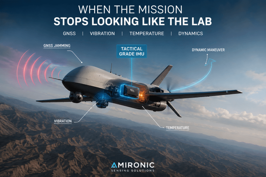
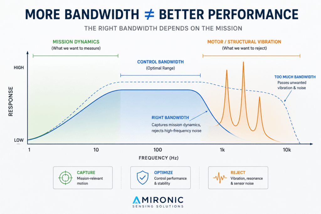
Figure 1: As mission conditions change, Tactical Grade IMU performance is tested as part of the complete system – against GNSS disruption, vibration, temperature changes, and high-dynamic motion.

Myth #1: The Higher the Bandwidth of a Tactical Gyro, the Better

It sounds almost obvious.

If we want a faster gyroscope, we want it to capture as much of the motion as possible. So 500 Hz sounds better than 200 Hz, and 1,000 Hz sounds even better.

But in a real system, more bandwidth does not necessarily mean better performance.

Gladiator Technologies also identifies the statement “Higher bandwidth always means better performance” as a myth. The right bandwidth depends on the application, the motion profile, and the system requirements.

Suppose our Tactical IMU is installed on a UAV.

The aircraft maneuvers, changes direction, and makes altitude corrections. These are exactly the motions we want the gyro to measure.

But at the same time, the motor is spinning, the propeller is generating vibration, the structure itself is responding to mechanical loads, and additional vibration frequencies may appear that have nothing to do with the motion the control system is actually trying to measure.

From the gyroscope’s point of view, there is no label saying:

“This is important mission-related motion.”

and:

“This is just motor vibration.”

The gyro measures what reaches it.

If we increase the bandwidth, we may capture faster dynamics, but we may also allow more high-frequency vibration and noise into the measurement chain.

If we reduce the bandwidth too much, we can create the opposite problem: filtering out some of the dynamics that the controller, stabilization system, or tracking system actually needs to see.

This is an important consideration when selecting a Tactical Grade Gyro or Tactical Grade IMU:

The largest number on the datasheet is not necessarily the right number for the mission.

The right question is not:

How Many Hz Does the Tactical Gyro Have?

It is:

Which Part of the Motion Do We Want the Gyro to See, and Which Part Do We Want the System to Reject?

That is the difference between selecting a component from a specification table and engineering an inertial system for a real mission.

Figure 2: In a Tactical Grade IMU, higher bandwidth is not necessarily better. The goal is to capture the dynamics that matter to the mission while minimizing the effects of structural vibration, resonance, and high-frequency noise.

Myth #2: A Tactical Grade Gyro Has to Be Large and Heavy

This myth also sounds reasonable.

For years, high inertial performance was associated with large, heavy, and expensive systems. So it is easy to assume that if an IMU is small enough to fit in the palm of your hand, its performance must also be “small.”

But sensor size alone does not determine performance.

Gladiator Technologies specifically notes that modern MEMS technology can provide a compact form factor without necessarily sacrificing the performance required for demanding applications.

This is especially important in systems where SWaP is an integral part of the mission requirements:

Size, Weight and Power.

In a small UAV, gimbal, EO/IR system, stabilized antenna, or autonomous payload, every gram and every cubic centimeter can affect the system architecture.

But there is an even more interesting point.

A Small IMU Does More Than Save Space. It Can Allow You to Measure at the Right Location.

Suppose we need to stabilize an EO/IR system.

We could install the IMU wherever it is mechanically convenient within the platform.

But is that really the point whose motion we want to measure?

A structure is not a perfectly rigid body. Between the platform body, mounting interfaces, gimbal, and payload, there may be vibration, flexing, resonances, and small dynamic differences.

The closer the IMU can be installed to the point whose motion the control system actually needs to understand, the more options the system designer may have.

In other words:

IMU placement is part of the measurement.

A compact Tactical Grade IMU may allow installation closer to the payload, rotation axis, camera, or subsystem being stabilized, rather than forcing the sensor location to be determined simply by the available space inside the enclosure.

And that changes the question.

Instead of asking:

Can a small Tactical Grade Gyro be accurate?

A better question is:

Does it provide the required performance, and can it be installed where the system actually needs to measure the motion?

This is no longer just a question of miniaturization.

It is a question of System Architecture.


But Here Comes the Bigger Myth: MEMS Is Not Really Tactical Grade

For years, there has been an almost intuitive distinction:

MEMS belongs in smartphones, automotive systems, and commercial applications.

A “serious” inertial system belongs to a different world.

But that distinction is no longer sufficient.

Gladiator Technologies also identifies the statement “MEMS can’t support demanding missions” as a myth, noting that MEMS technology has advanced well beyond basic applications and can support systems in which Performance, Reliability, Size, Weight, and Power all matter simultaneously.

That leads to a much better question than:

Is It MEMS?

The question should be:

What Kind of MEMS?

What is the Bias?

What is the Angle Random Walk?

How does the Scale Factor behave?

What happens across the operating temperature range?

What is the Bandwidth?

What is the Data Rate?

What is the Latency?

How are Calibration and Compensation handled?

And what happens to all of these when the sensor leaves the laboratory and enters a platform that vibrates, heats up, and maneuvers?

Only when these parameters are connected to the actual mission requirements does it make sense to seriously discuss a MEMS Tactical IMU, a Tactical Grade IMU, or a Tactical Grade Gyroscope.

Because “Tactical Grade” is not a label that magically turns a sensor into a tactical sensor.

The mission determines whether its performance is truly Tactical Grade.


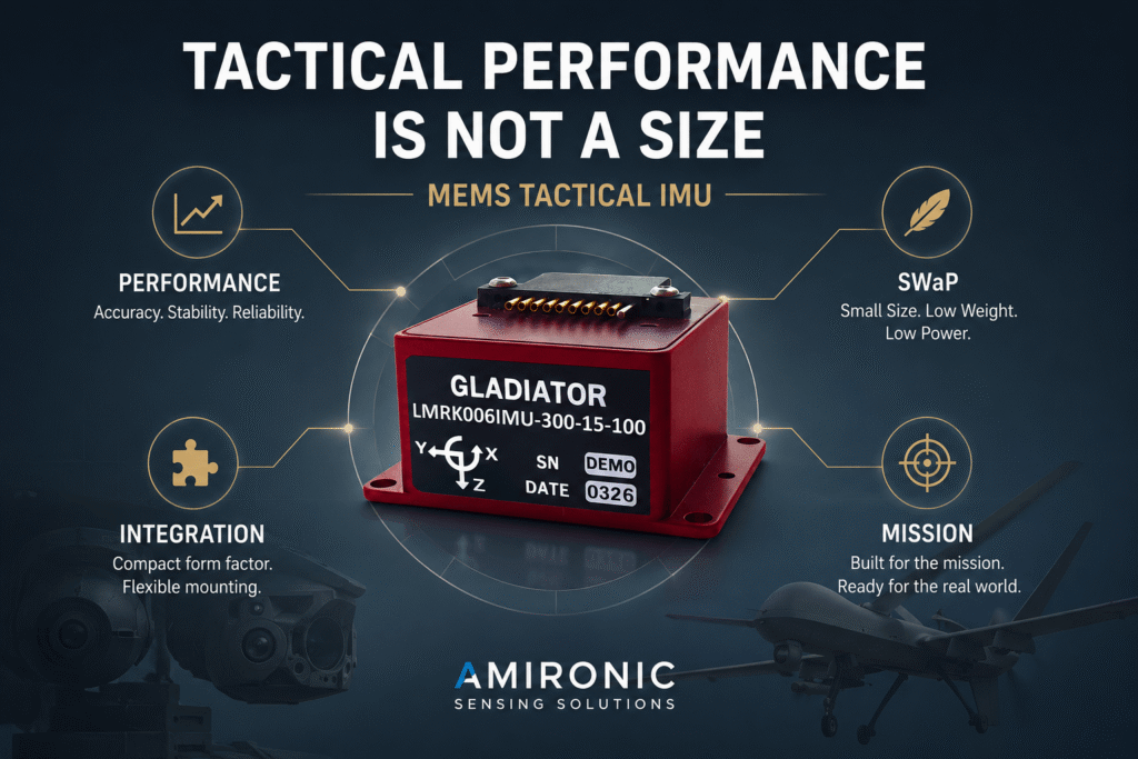
Figure 3: A Tactical Grade IMU does not have to be large to deliver high performance. MEMS technology can combine accuracy, stability, and reliability with low SWaP and flexible installation – depending on the mission requirements.

And Now Comes the Dangerous Part: The IMU Is Still Working

It is relatively easy to deal with a sensor that has stopped working.

If communication is lost, power disappears, or the system receives a clear Fault indication, the mission computer knows there is a problem and can respond accordingly.

But what happens when the IMU does not stop working?

It is still transmitting.

The numbers are still coming in.

There is no error message.

Suppose that, at a certain moment, the navigation system receives:

Pitch = 12.43°

That looks like very precise information.

But in an operational system, the important question is not simply what number was received.

The question is:

How confident are we that those 12.43° still represent reality with the accuracy required by the mission?

And this is where we move beyond the specifications of a Tactical IMU and into a much more interesting system-level question:

IMU Trust

“Trust” is not necessarily a field you will find in an IMU datasheet.

It is a system-level concept.

An operational system does not simply need to receive measurements. It needs to know how to treat those measurements as mission conditions change.

Let’s return to our unmanned platform.

A few minutes ago, everything was working normally.

GNSS was providing position.

The Tactical Grade IMU was providing acceleration and angular rate measurements.

The navigation system was combining the information.

Then something begins to change.

GNSS does not disappear.

Instead, the position it reports begins to drift gradually.

Not a sudden one-kilometer jump that would immediately cause the system to declare that something is wrong.

Perhaps just a small shift.

Then a few more meters.

And a few more.

From the mission computer’s perspective, two sources of information that agreed only moments ago are now beginning to tell two different stories about the same reality.

GNSS says the platform is here.

The IMU-based inertial solution points somewhere slightly different.

Which One Is Right?

That is a critical question.

If the GNSS source is disrupted or providing misleading information, blindly using it could cause the system to “correct” a valid inertial solution toward information that is actually wrong.

But the opposite approach is not a magic solution either.

An IMU measures acceleration and angular rate. An inertial navigation solution based on those measurements accumulates errors over time.

So the algorithm cannot simply say:

GNSS looks suspicious? From now on, trust the IMU.

The system needs to evaluate the information in a broader context.

Does the reported change in position match the motion observed by the inertial sensors?

Is the angular rate consistent with the dynamics of the platform?

Has any sensor reached saturation?

Has an unusual vibration pattern appeared?

Has there been a significant change in temperature?

Do other sources of information in the system support one version of events over the other?

The key point is that a Tactical Grade IMU does not operate in isolation.

It is part of a chain in which a measurement ultimately becomes a decision.

And as the mission becomes more demanding, understanding how much trust to place in each measurement can become almost as important as the measurement itself.


What Happens When GNSS and the Tactical IMU Start Telling Two Different Stories?

This is exactly where the difference begins to emerge between a system that simply contains an IMU and one that actually knows how to use it.

Under normal conditions, GNSS and IMU complement each other.

GNSS provides an external reference that does not suffer from the same error accumulation inherent in inertial navigation.

The IMU, on the other hand, provides continuous, high-rate information about motion and does not depend on receiving satellite signals in order to measure acceleration and angular rate.

When both sources agree, life is easy.

The challenge begins when they stop agreeing.

And that can happen without either source ever going “offline.”

That is why, in a real system, sensor availability is not the same as data trustworthiness.

A sensor can be online and continuously providing data while the system still needs to treat that information with caution.

And this may be one of the most important points in any discussion of a Tactical IMU:

In an operational system, the question is not only “Do I have data?” but “Is this data still consistent with what the system knows about the real world?”

Figure 4: When GNSS data and the inertial solution begin to diverge, the challenge is not simply to detect the discrepancy, but to determine which source of information can be trusted – and to what degree.

Tactical Grade Is Not Just About Accuracy – It Is a Chain of Trust

It is easy to focus on the IMU itself.

Open the datasheet, check Bias, Noise, Scale Factor, Bandwidth, and temperature performance, and compare the numbers.

But the data that eventually reaches the mission computer has traveled through a much longer chain.

In simplified form:

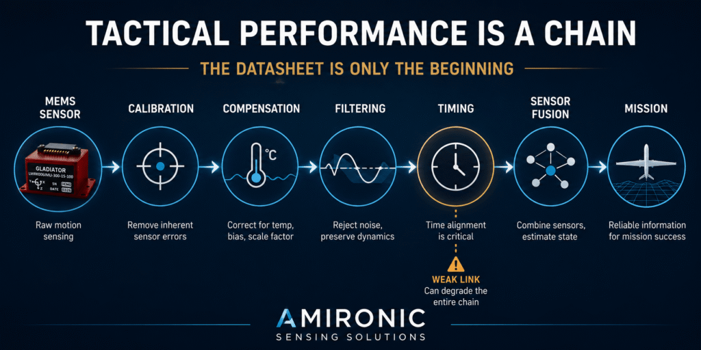
MEMS Sensor → Calibration → Compensation → Filtering → Timing → Sensor Fusion → Health Monitoring → Mission Computer

And every link in that chain can affect the final result.

An excellent gyroscope with improper timing can cause the system to interpret motion as having occurred slightly earlier or later than it actually did.

A low-noise IMU installed at a location exposed to significant structural vibration may provide measurements that are more difficult for the system to use effectively.

A Tactical Grade IMU with excellent Bias performance, but inadequate compensation across the relevant temperature range, may behave differently as the platform transitions from a cold environment to higher internal temperatures during the mission.

And a Sensor Fusion algorithm that places too much weight on a source that has become questionable can turn good measurements into a poor navigation solution.

In other words, between the MEMS Gyroscope and the decision made by the mission computer lies an entire chain of trust.

And that changes the way we should think about Tactical Grade.

Tactical Grade Is Not a Single Number on a Datasheet

Suppose two Tactical IMUs have similar Bias Instability specifications.

Does that mean they will deliver the same performance once installed on the platform?

Not necessarily.

One may behave better across temperature.

The other may offer Bandwidth that is better suited to the dynamics of the application.

One may provide a very high Data Rate, but with Latency that is not appropriate for the control loop.

The other may integrate more effectively in terms of Synchronization with a camera, encoder, or mission computer.

And one may offer simpler Mechanical Integration, allowing the sensor to be positioned closer to the point whose motion actually needs to be measured.

So the question:

“Which Tactical Grade IMU is more accurate?”

may simply be the wrong question.

A better one is:

Which Tactical IMU Allows the Complete System to Maintain Performance as Conditions Begin to Change?

And that brings us to another myth from Gladiator’s Engineering Mythbusters.

Myth #4: The IMU Was Factory-Calibrated – So We’re Done

Calibration is one of the most important steps in transforming a MEMS sensor into a high-performance inertial product.

But calibration does not exist in a sterile world.

Gladiator notes that sensor performance can be affected by temperature, aging, environmental conditions, and application-specific factors, meaning that calibration is not necessarily a simple “one and done” process.

And that leads to an important point that is easy to overlook:

The Tactical IMU Left the Factory Calibrated. The Platform Did Not.

Once the IMU leaves the manufacturer, it is installed inside a real system.

There is a mounting interface.

There is a PCB.

There is an enclosure.

There are heat sources.

There are motors.

There are cables and connectors.

There is a mechanical structure transmitting vibration.

And there is an entire platform that expands, contracts, vibrates, and maneuvers.

The IMU itself may be excellent, while the system’s Installed Performance can still differ from what the engineer expected when reading the datasheet.

That distinction is critical.

Sensor Performance is what the sensor itself is capable of delivering.

Installed Performance is what the system is actually able to achieve with that sensor once it has been integrated into the real world.

And in a tactical system, the real world is exactly where performance matters most.

Figure 5: Tactical Grade IMU performance does not end with the sensor itself. Calibration, temperature compensation, filtering, timing, and sensor fusion form a single chain – and one weak link can affect the performance of the entire system.

So What Happens When the System Begins to Lose Trust?

So far, we have focused on the problem.

But an operational system also has to make a decision.

Let’s return to our platform.

GNSS begins to drift. The vibration environment has changed. Temperature has increased. The Tactical IMU is still operating and continues to provide data.

The navigation system cannot stop and ask an engineer to open the log file.

It has to keep operating.

In real time.

And this is where an important concept comes into play:

Sensor Health Monitoring

The idea is not simply to ask whether the sensor is alive or dead.

The goal is to identify situations in which data is still being received, but something in its behavior is beginning to deviate from what the system expects.

For example:

  • Is one of the Gyroscope axes approaching Saturation?
  • Has the noise level changed abnormally?
  • Has a vibration spectrum appeared that was not present before?
  • Is the acceleration data consistent with the motion the system expects to see?
  • Is there a growing discrepancy between GNSS and the inertial solution?
  • Is a change in temperature occurring at the same time as a change in sensor behavior?

None of these questions alone necessarily proves that the IMU has failed.

But together, they can provide the system with something extremely important:

Context.

And context is exactly what is missing when we look only at the number coming from the sensor.


Not Every Fault Should Trigger a Red Light

In simple systems, we tend to think in binary terms:

GOOD / BAD

or:

VALID / INVALID

But in the real world, there is a lot of gray in between.

Suppose the system detects an unusual increase in vibration.

Should it immediately reject the Tactical Gyro?

Not necessarily.

Perhaps the motor has simply entered a different RPM range.

Perhaps the platform is maneuvering.

Perhaps the system is experiencing a temporary structural resonance.

Or perhaps the measurement quality really has begun to degrade.

An advanced system can therefore treat information quality not simply as a 0-or-1 switch, but as a variable level of confidence.

In other words:

Sensor Available Does Not Necessarily Mean Sensor Trusted.

That is a major distinction.

A sensor can be connected, active, and transmitting thousands of measurements per second, while the navigation system may still decide that its data should be given a different weight within the Sensor Fusion solution at that particular moment.


And Then GNSS Disappears Completely

Until now, we have allowed GNSS to remain “suspicious.”

Now suppose the platform enters an environment where GNSS is no longer available.

There is no external position reference.

There are no continuous GNSS corrections.

From this moment on, the quality of the inertial information takes on an entirely different significance.

A small Angular Rate error can integrate over time into an attitude error.

An Orientation error can affect the system’s ability to distinguish vehicle acceleration from the gravity vector.

And acceleration errors, when integrated over time, become velocity errors and eventually position errors.

In other words, the problem is not that the Tactical IMU “stops working” when GNSS disappears.

Quite the opposite.

That Is Exactly When Its Real Test Begins.

This also explains why two IMUs that appear very similar on a specification table can produce very different results when a platform transitions into GNSS-Denied Operation.

Small differences in Bias, Angle Random Walk, Scale Factor, temperature behavior, and other error sources do not necessarily remain “small” as time passes.

They accumulate.

And time is one of the greatest enemies of inertial navigation.


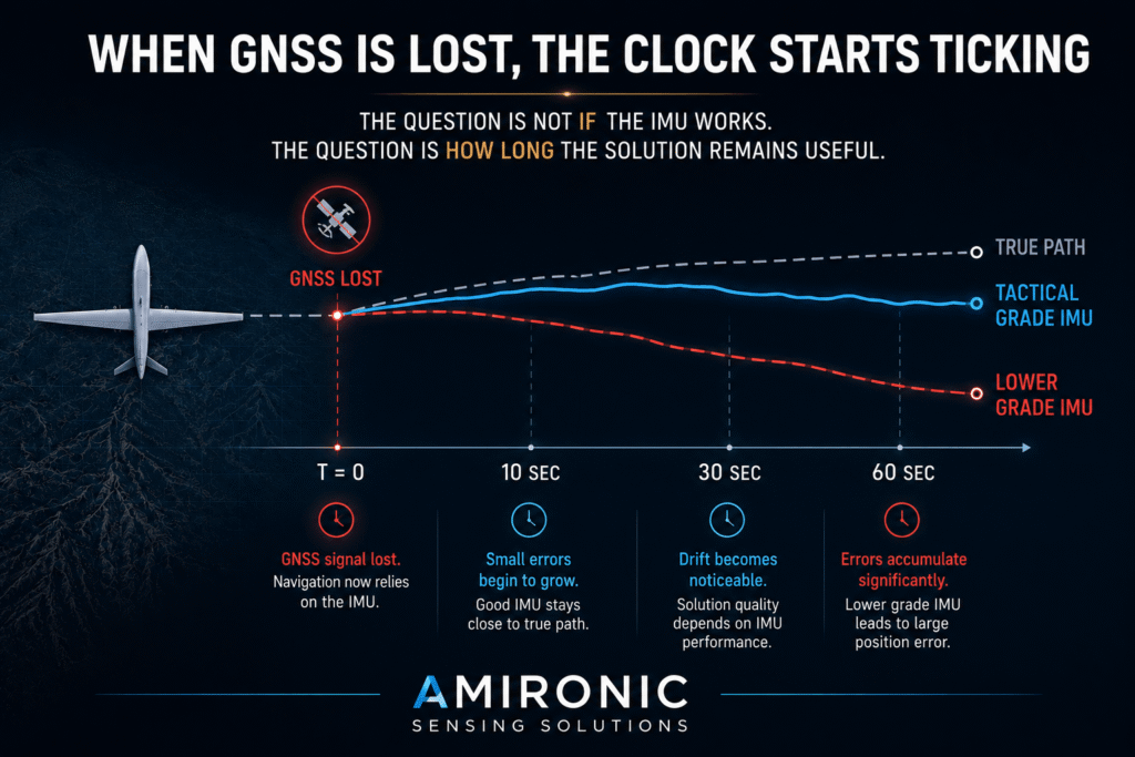
The Clock Starts Ticking the Moment GNSS Is Lost

Think of that moment as starting a stopwatch.

T = 0

GNSS is lost.

The platform keeps moving.

After one second, the inertial solution may still look excellent.

After ten seconds, differences between systems can begin to matter.

After one minute, the quality of the Tactical IMU, the error model, Calibration, and Sensor Fusion may matter much more.

And if the mission requires extended operation without an external reference, the question is no longer:

“Does the IMU work without GPS?”

Almost any IMU can continue outputting measurements without GPS.

The real question is:

How Long Does the Solution Based on It Remain Good Enough to Complete the Mission?

That is a completely different question.

Because Tactical Grade is not an absolute target.

It is tied to the operational requirement.

A system that needs to survive five seconds without GNSS does not necessarily require the same inertial solution as a system that needs to continue navigating for several minutes.

And a system that only needs to maintain Attitude does not necessarily require the same performance as a system that also needs to maintain Position.

The same Tactical Grade IMU can be an excellent fit for one mission and insufficient for another.

And that brings us directly back to Gladiator’s central point:

The “best” IMU is not necessarily the one with the biggest numbers. It is the one whose performance characteristics are best matched to the mission.

Figure 6: When GNSS reception is lost, inertial errors begin to accumulate. The difference between IMUs at different performance levels becomes evident in the operational question that really matters – how long the navigation solution remains useful for the mission.

So What Really Makes an IMU Tactical Grade?

After all of this, it is tempting to look for a single number that provides a simple answer.

Low enough Bias Stability?

Angle Random Walk?

Bandwidth?

Shock?

Temperature range?

The answer is that there is no single specification that makes an IMU Tactical Grade.

The real meaning comes from the combination of those parameters and how well they match the mission.

A good example is the LandMark 006 IMU from Gladiator Technologies.

It is a six-axis MEMS IMU designed for stabilization and precision measurement in demanding environments. The manufacturer specifies an ARW of 0.0254°/√hr, typical Bias Stability of 0.8°/h, and a Gyro measurement range of ±300°/sec.

But this is exactly where it is important not to stop at the numbers.

Example 1: EO/IR Stabilization

Suppose the Tactical IMU is being used to stabilize an electro-optical payload on a UAV.

In this application, Bias matters, but it is not the only consideration.

A fast control loop needs dynamic information at the right time.

The VELOX Plus version of the LandMark 006 can provide up to 600 Hz Bandwidth, a 10 kHz Data Rate, and a 20 µs Digital Message Delay.

This is where those three numbers begin to connect to the mission.

10 kHz tells us how frequently data can be delivered.

600 Hz describes the maximum bandwidth.

20 µs refers to the message delay.

These are three different things.

In a high-speed stabilization system, receiving a large number of samples is not enough. The data must represent the relevant dynamics and arrive at the right time for the control loop.

So for an EO/IR system, the question is not only:

“What is the Bias of the Tactical Gyro?”

It is also:

“How quickly do I know that the motion occurred?”


Example 2: A Small UAV Where Every Gram Matters

Now the same family of requirements encounters a different problem.

There is not much space.

There is not much power available.

And every additional gram affects the payload.

The LandMark 006 weighs approximately 17 grams, with body dimensions of approximately 25.4 × 25.4 × 15.8 mm and a volume of approximately 0.63 cubic inches. Typical power consumption is specified at 500 mW.

Suddenly, SWaP is no longer a minor line on the specification sheet.

It becomes part of the operational capability.

A smaller IMU may allow the engineer to position it closer to the payload, reduce mass, lower power requirements, and preserve more of the SWaP budget for the camera, mission computer, communications, or other subsystems.

This is where a MEMS Tactical IMU becomes interesting not only as a sensor, but as part of the overall system architecture.


Example 3: What Happens When the Environment Itself Becomes the Enemy?

Our platform does not remain in a laboratory at 25°C.

It may begin its mission in the cold, heat up during operation, and experience Shock and Vibration at the same time.

The LandMark 006 is specified as calibrated from -50°C to +85°C, with an Operational Vibration rating of 8 g RMS from 50 Hz to 2 kHz and Operational Shock of 1000 g, 0.5 ms half-sine.

Now we can see why the term Tactical Grade IMU should not be based on Bias alone.

The sensor has to measure motion while it is itself operating inside a dynamic, vibrating, and thermally changing environment.

And the system designer has to understand how those performance characteristics relate to the mission.


Example 4: GNSS Is Lost – Now Bias and ARW Mean Something Different

Let’s return to the moment when GNSS was lost.

There is now no continuous external reference helping to constrain the accumulation of inertial errors.

The LandMark 006 specifies typical Bias Stability of 0.8°/h and an ARW of 0.0254°/√hr.

But even here, we should never take one specification and declare:

“This means the system will navigate with X accuracy for Y minutes.”

That is not what the datasheet says.

Actual navigation performance depends on the INS architecture, Sensor Fusion, platform dynamics, Alignment, additional aiding sources, and the mission requirements.

And that may be one of the most important lessons in this entire article:

A good datasheet helps us understand the building blocks of the solution. It does not replace System Engineering.


Don’t Look for the Tactical IMU With the Biggest Number

Look for the one that fits the mission.

For an EO/IR system, Bandwidth, Message Delay, and Synchronization may be especially important.

For a system operating in a GNSS-Denied environment, Bias, ARW, and behavior over time may carry greater weight.

In a small UAV, SWaP can become a primary constraint.

And on a platform exposed to wide temperature ranges and significant vibration, Calibration, Compensation, and environmental performance become essential parts of the selection process.

The same IMU can be an excellent solution for one application and a poor fit for another.

So the question is not:

What Is the Best Tactical Grade IMU?

It is:

What Is the Right Tactical Grade IMU for the Mission?

And that is exactly why selecting an IMU begins with the datasheet, but should never end there.

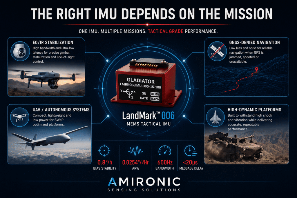
Figure 7: There is no single Tactical Grade IMU that fits every mission. The LandMark 006 combines 0.8°/h Bias Stability, 0.0254°/√hr ARW, up to 600 Hz Bandwidth, and 20 µs Message Delay with low SWaP – a combination suited to EO/IR stabilization, autonomous systems, and demanding high-dynamic platforms.

Conclusion: Tactical Grade Begins Where the Datasheet Ends

Selecting an IMU is easy when you focus on a single line in a specification table.

It becomes much harder when you need to understand what happens after installation, inside a real system, as temperature changes, the structure vibrates, the platform maneuvers, and external sources of information can no longer be taken for granted.

And that is the central point of this article.

A Tactical Grade IMU is not a collection of impressive specifications. It is a component that must match the mission.

Sometimes inertial accuracy will be the deciding factor. Sometimes it will be dynamics. Sometimes timing. Sometimes SWaP. And sometimes it is the combination of all of them that determines whether the information coming from the IMU remains useful at the moment the system needs it most.

The LandMark 006 from Gladiator Technologies is a good example of this approach: a compact MEMS Tactical IMU that combines inertial performance with high Data Rate, wide Bandwidth, low Message Delay, and calibration across a wide temperature range, all in a package weighing approximately 17 grams.

But even here, the message is not to select an IMU simply because it has the largest or smallest number in the table.

Quite the opposite.

Don’t look for the best Tactical IMU on paper.
Look for the right Tactical IMU for your mission.

Because ultimately, the real test is not what is written on the datasheet.

The real test begins when the mission stops behaving like the lab.

🧩 Further Reading and Deeper Insight

This article is part of a broader series exploring the engineering principles behind modern inertial sensing and motion stability in advanced control and navigation systems. For deeper technical context and system-level insights, you may also find the following articles valuable:

  • Bridging Control and Navigation: How Advanced MEMS IMUs Are Redefining System Performance
  • Gyro and IMU for Advanced Control Systems
  • The Silent Problem of Precision Systems – Why Gyros and IMUs Are Control Components, Not Just Sensors
  • Why External Sync is Critical in Gyro and IMU Systems
  • Stabilization, Tracking & Time Sync: The Foundation of Precise Line-of-Sight Control
  • Mission-Grade Stabilization in Dynamic EO/IR Systems: Why Bandwidth, Data Rate, and Phase Lag Define Gimbal Performance
  • Why Gladiator? What Truly Differentiates a High-End MEMS IMU Manufacturer
  • Common Misconceptions About MEMS Inertial Sensors
  • Bias Stability vs. Bias Instability: What really determines the performance of Gyro and IMU systems in stabilization, tracking, and navigation
  • Scale Factor in MEMS IMUs – The Error That Quietly Destroys Accuracy
  • The IMU Was Excellent. The Image Still Shook.
  • 2000Hz IMU? Before You Get Impressed, Understand Three Completely Different Numbers
  • SX3: Pushing MEMS Beyond Traditional Stabilization
  • Why a Smaller IMU Can Save Months of Development
  • Your Image Still Shakes Despite Choosing a Gyroscope with Excellent Bias Stability
  • Why Replacing an IMU Can Lead to Weeks of Recalibration
  • From IMU to INS: How a Tactical Navigation System Is Really Built
  • When GPS Is Lost, It’s Already Too Late to Choose an IMU
  • Why Do Counter-UAS Systems Lose Track of a Drone Right After Detecting It?
  • When GPS Lies: Why IMUs Are Becoming Mission-Critical in the Era of Autonomous Wingmen
  • How Does a MEMS Sensor Become a Tactical-Grade IMU?
  • The Antenna Hasn’t Moved – So Why Did We Lose the Link? The Role of the IMU in Antenna Positioning Systems

Frequently Asked Questions – Tactical IMU and Tactical Grade IMU

What Is a Tactical Grade IMU?

A Tactical Grade IMU is an inertial measurement unit designed for demanding applications involving stabilization, control, measurement, and inertial navigation. No single specification makes an IMU Tactical Grade. Suitability depends on a combination of inertial performance, dynamics, temperature behavior, vibration, timing, and mission requirements.

What Is a Tactical Grade Gyro?

A Tactical Grade Gyro is a gyroscope with performance characteristics suitable for demanding tactical applications. When selecting a Tactical Gyro, engineers should consider not only Bias Stability, but also Angle Random Walk, Scale Factor, Bandwidth, temperature behavior, vibration, and other application-specific parameters.

Can a MEMS IMU Be Tactical Grade?

Yes. Modern MEMS technology can support demanding applications. Gladiator Technologies identifies the idea that MEMS cannot support demanding missions as a myth, emphasizing that selection should be based on performance and application requirements rather than sensor technology alone.

Can a Tactical Grade IMU Operate Without GNSS or GPS?

Yes. An IMU does not depend on GNSS to measure acceleration and angular rate, so it continues to provide inertial measurements when GNSS is unavailable.

However, errors in an inertial navigation solution accumulate over time. The important question is therefore not simply whether the IMU continues to operate, but how long the resulting solution remains accurate enough to meet the mission requirements.

Which Specifications Are Important When Selecting a Tactical IMU?

The relevant parameters depend on the application, but typically include Bias Stability, Angle Random Walk, Bias over Temperature, Scale Factor Error, Bandwidth, Data Rate, Message Delay, External Sync, Shock, Vibration, and SWaP.

For example, the Gladiator LandMark 006 IMU offers typical Bias Stability of 0.8°/h, ARW of 0.0254°/√hr, and a Scale Factor Error of 500 ppm. The VELOX Plus version supports up to 10 kHz Data Rate, 600 Hz Bandwidth, and 20 µs Digital Message Delay.

What Applications Can Use a MEMS Tactical IMU?

Depending on system requirements, a MEMS Tactical IMU can be used in UAVs and autonomous systems, EO/IR and gimbal stabilization, tracking and control systems, and inertial navigation solutions.

Gladiator specifically positions the LandMark 006 for stabilization and precision measurement in demanding environments.

How Do You Select the Right Tactical Grade IMU?

Do not begin with the question “Which IMU is the best?”

Begin with:

“What does the mission require?”

Define the platform dynamics, required accuracy, vibration and temperature environment, timing requirements, SWaP constraints, and the required duration of operation under conditions such as GNSS loss. Only then should different Tactical IMUs be compared.

The right Tactical Grade IMU is not necessarily the one with the most impressive specifications – it is the one whose performance best matches the mission.

Key Terms

Tactical IMU – An inertial measurement unit intended for demanding navigation, stabilization, tracking, and control applications.

Tactical Grade IMU – An IMU providing a level of inertial performance suitable for tactical applications. Suitability is determined by the combination of inertial, dynamic, environmental, and system-level requirements rather than by a single specification.

Tactical Gyro / Tactical Grade Gyro – A gyroscope with performance characteristics suitable for demanding tactical applications, either as a standalone sensor or as part of an IMU.

MEMS Tactical IMU – A Tactical Grade IMU based on MEMS technology. Modern MEMS technology can support applications requiring high performance together with low Size, Weight, and Power.

Bias Stability – A measure of the stability of a sensor’s bias over time. The LandMark 006 specifies typical Gyro Bias Stability of 0.8°/h.

Angle Random Walk – ARW – A measure associated with random gyroscope noise and its contribution to accumulated angular error. The LandMark 006 specifies an ARW of 0.0254°/√hr.

Scale Factor Error – The error in the relationship between the actual input motion and the value measured by the sensor. The LandMark 006 specifies a typical Scale Factor Error of 500 ppm.

Bandwidth – The frequency range over which the sensor can respond to motion dynamics. Higher Bandwidth is not necessarily better and should be matched to the motion profile and system requirements.

Data Rate – The rate at which the IMU provides digital measurement data to the system. The LandMark 006 with VELOX Plus supports a Data Rate of up to 10 kHz.

Message Delay / Latency – The time between a measurement and the availability of that information to the system. The LandMark 006 with VELOX Plus specifies a Digital Message Delay of 20 µs.

External Sync – The ability to synchronize IMU measurements with an external clock or events elsewhere in the system, such as a camera, encoder, or mission computer. The LandMark 006 with VELOX Plus supports External Sync rates of up to 10 kHz.

Sensor Fusion – The process of combining information from multiple sensors or data sources, such as an IMU and GNSS, to produce an integrated solution.

GNSS-Denied Navigation – Navigation in an environment where GNSS signals are unavailable or cannot be reliably used. In such conditions, inertial information becomes particularly important.

Sensor Health Monitoring – Monitoring sensor behavior and measurement data to identify anomalies, saturation, vibration effects, or inconsistencies with other information sources.

SWaP – Size, Weight and Power – The size, weight, and power requirements of a system or component. SWaP is especially important in UAVs, EO/IR systems, and autonomous platforms. The LandMark 006 weighs approximately 17 grams, has a volume of approximately 0.63 in³, and typical power consumption of 500 mW.

Tags: Gladiator_Technologies

Related Articles

Why Replacing an IMU Can Lead to Weeks of Recalibration

12/07/2026amironicLTD

Gladiator Technologies Releases Next-Generation SX2 Inertial Sensors

30/01/2021amironicLTD

When GPS Lies: Why IMUs Are Becoming Mission-Critical in the Era of Autonomous Wingmen

04/08/2026amironicLTD

Recent Posts

  • Tactical Grade IMU: What Happens When the Mission Stops Behaving Like the Lab?
  • Why Run Electricity to the Button When Herga Can Switch It with Air?
  • Fighter Aircraft Without a Pilot: How Do You Build a Nervous System for an Aircraft That Must Make Its Own Decisions?
  • Why a Standard Pressure Sensor Isn’t Always Suitable for Hydrogen Systems
  • Hands on the Keyboard, Foot on the Radio – Why Push-to-Talk Is Moving to the Floor in Control Rooms

Categories

  • Air Switch
  • Circuit Breakers
  • Elapsed Time Indicator
  • Feedthrough
  • Footswitches
  • Gears & Transmission
  • Hour Meters
  • Infra Red Switches
  • INFRARED LAMPS
  • Low Noise Inertial MEMS
  • Mechanics
  • MEMS Gyroscope
  • MEMS Inertial
  • Microelectronics
  • Motors
  • Position Sensors
  • Power Supply
  • Pressure Sensors
  • Pressure Switch
  • Temperature Sensors
  • Tungsten and Molybdenum
  • Uncategorized
  • Vacuum Switches

Quick Contact

Fill out the form and our representatives will return to you

    Name (required)

    Email (required)

    Phone

    Message

    This site is protected by reCAPTCHA and the Google
    Privacy Policy and
    Terms of Service apply.

    Amironic Ltd.

    3 Rabinovich Street, Petah Tikva 4928144 , Israel. Tel: +972-3-9047744 E-mail: office@amironic.co.il
    Email
    Facebook
    Twitter
    LinkedIn
    YouTube
    Press on the ISO Certificate below for download
    ISO 9001:2015 Certification
    • MEMS Inertial
    • Circuit Breakers
    • Footswitches
    • Mechanical & Transmisions
    • Sensors
    • Motors
    • Electronics
    • Hand Control
    • Power Solutions

    News

    • Tactical Grade IMU: What Happens When the Mission Stops Behaving Like the Lab?
    • Why Run Electricity to the Button When Herga Can Switch It with Air?
    • Fighter Aircraft Without a Pilot: How Do You Build a Nervous System for an Aircraft That Must Make Its Own Decisions?
    • Why a Standard Pressure Sensor Isn’t Always Suitable for Hydrogen Systems
    • Hands on the Keyboard, Foot on the Radio – Why Push-to-Talk Is Moving to the Floor in Control Rooms
    About AmironicContactעברית
    © 2022 Amironic All rights reserved. All Trademarks are the property of their respective owners.
    • Increase Font
    • Decrease Font
    • Black & White
    • Inverse Colors
    • Highlight Links
    • Regular Font
    • Reset