Bias, Noise, Bandwidth, Latency and Dynamic Range – How to Balance Them When Selecting a MEMS IMU for Control, Stabilization and Navigation Systems
When engineers compare a MEMS IMU, MEMS Gyroscope, or Tactical Grade IMU, it is easy to start with the headline numbers on the datasheet.
Which IMU offers lower Bias Instability?
Which one has better Angular Random Walk?
Which Gyroscope has lower Noise?
These are important questions, but in a dynamic system, they are not enough.
Two MEMS IMUs may look very similar, and one may even appear more accurate on paper. However, once integrated into a stabilization system, Gimbal, EO/IR system, UAV, tracking system, or autonomous platform, the IMU that appears less accurate in the datasheet may actually deliver better system-level performance.
The reason is simple: an IMU does not operate in an isolated laboratory environment. It is part of a dynamic system in which the platform rotates, accelerates, vibrates, and changes direction, while the control system must acquire the data, process it, and respond in time.
Selecting a MEMS IMU for a dynamic system therefore requires several parameters to be considered together:
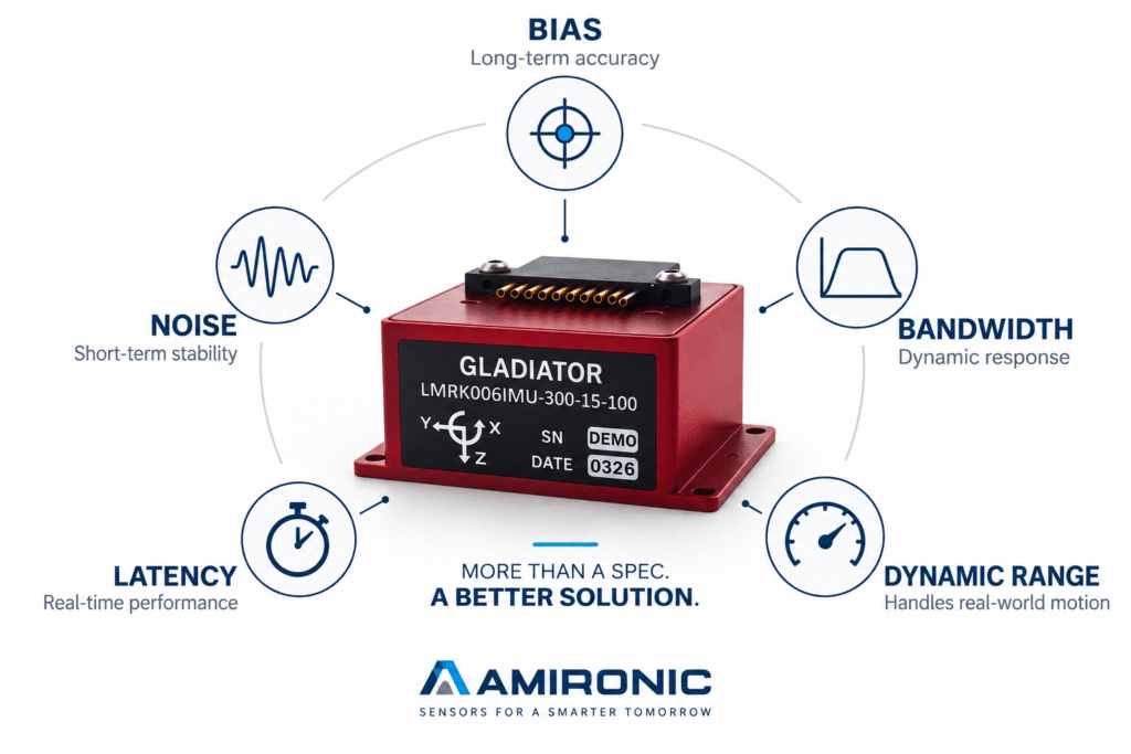
Bias, Noise, Bandwidth, Latency, Data Rate, and Dynamic Range.
The right question is not simply:
Which IMU is more accurate?
It is:
Which IMU provides the right combination of performance characteristics for the dynamics of the system?
No Single Specification Defines a “Good IMU”
Imagine an engineer comparing two Tactical Grade IMUs.
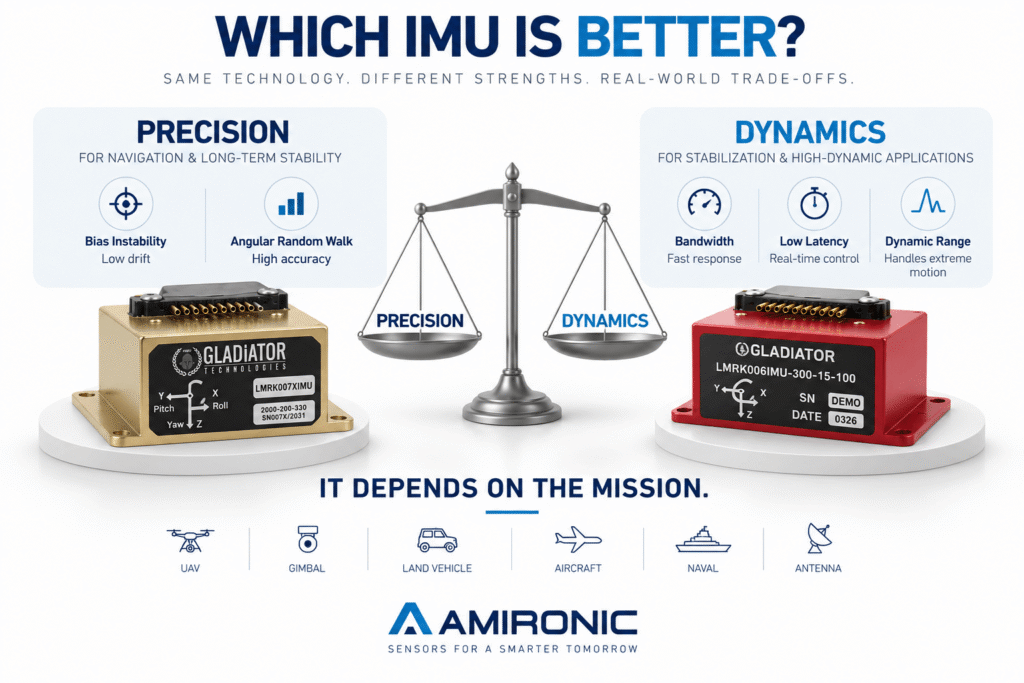
The first offers better Bias Instability and Angular Random Walk (ARW).
The second has slightly higher Bias, but offers wider Bandwidth, lower Latency, and a significantly higher Angular Rate Range.
Which one is better?
There is no single answer.
For a navigation system that must maintain accuracy over time when GNSS is unavailable, Bias and ARW performance may carry significant weight.
But for a MEMS IMU used in a fast stabilization system, EO/IR system, Gimbal, stabilized antenna, or dynamic tracking system, parameters such as Bandwidth, Noise, Latency, and Dynamic Range may be equally important – and sometimes more important.
This is one of the most common mistakes when selecting a Gyroscope or IMU:
Comparing two products according to the parameter that makes it easiest to declare a “winner.”
In a real system, there may be no such winner.
Bias Instability – Important, but Not an Overall IMU Performance Score
Bias Instability is one of the specifications most closely associated with the performance of a MEMS Gyroscope or MEMS IMU, and for good reason.
Bias error affects the ability to estimate angular motion over time, making it particularly important in inertial navigation, Dead Reckoning, and applications where the system must operate without an external aiding source.
However, this does not automatically mean that an IMU with lower Bias Instability will provide better performance in every application.
For example, a fast stabilization system may be highly sensitive to higher-frequency motion. In such a case, a Gyroscope with excellent Bias performance but limited Bandwidth or higher Latency may be less suitable than a sensor with slightly higher Bias but better dynamic response.
In other words:
Bias describes an important part of sensor performance – but it does not, by itself, describe control-system performance.
Noise – Even a Stable IMU Can Produce an Unstable System
Two Gyroscopes can offer excellent Bias Stability and still behave very differently inside a control loop.
One reason is Noise.
In a long-duration navigation system, accumulated error over time is a major concern. In a stabilization system, however, noise within the frequency range of the control loop can feed directly into the correction mechanism.
The result may be:
Small oscillations, Jitter, unnecessary motor or actuator movement, and degraded Line-of-Sight stability.
Therefore, when selecting a MEMS Gyroscope for a Gimbal or a MEMS IMU for an EO/IR system, it is not enough to ask about Bias.
The noise characteristics of the sensor, and their relationship to the system Bandwidth and filtering, must also be understood.
Bandwidth – How Fast Can the MEMS Gyroscope Really See the Motion?
Bandwidth is one of the most important parameters in dynamic systems.
A system may receive thousands of samples per second, but the more important question is:
How much of the platform’s physical motion can the sensor actually measure in a useful way?
This is where it becomes important to distinguish between Sampling Rate, Output Data Rate, and Bandwidth.
A high Data Rate does not guarantee that the sensor provides useful information over the same frequency range.
If significant platform motion occurs outside the effective Bandwidth of the IMU, the control system does not receive a complete picture of what is happening – even if the output rate looks impressive on the datasheet.
In a dynamic system, Bandwidth is therefore not just another specification.
It is part of the direct relationship between the physical motion of the platform and the ability of the control system to respond to it.
Latency – What Happens While the System Is Waiting for the Measurement?
Motion can be measured very accurately, but if the information arrives too late, it may be less useful to a fast control system.
Consider a platform rotating at:
300°/s
If the measurement chain introduces 5 ms of Latency, the platform will have moved:
300 × 0.005 = 1.5°
During 20 µs, however, it moves only:
300 × 0.00002 = 0.006°
These numbers do not necessarily represent the actual system error – the control system may use prediction, compensation, and other algorithms – but they demonstrate why MEMS IMU Latency can become increasingly important as system dynamics become faster.
This is an important point that can easily be missed when two IMUs are compared only by Bias or ARW.
A highly accurate measurement that arrives late is not necessarily the best measurement for a dynamic control loop.
Dynamic Range – What Happens When the Gyroscope Reaches Its Limit?
Suppose we select a MEMS Gyroscope with a ±300°/s range.
During normal operation, the system reaches only 50°/s, so the available margin appears more than sufficient.
But what happens during a rapid maneuver, shock event, or unusual transient in which the angular rate briefly reaches 450°/s?
The sensor may reach Saturation.
At that point, the control system is no longer receiving a complete representation of the actual motion.
This is why the required Angular Rate Range should not be based solely on the typical behavior of the system.
At a minimum, the following should be understood:
Typical Motion → Maximum Expected Motion → Transient Events → Required Margin
The same principle applies to acceleration axes.
An Accelerometer Range that is too low may lead to Saturation during dynamic events, while a range far higher than necessary may involve other trade-offs.
And Then Comes the Real Trade-Off
Consider three theoretical IMUs:
| Parameter | IMU A | IMU B | IMU C |
|---|---|---|---|
| Bias / ARW | Excellent | Very Good | Good |
| Noise | Very Low | Low | Moderate |
| Bandwidth | Moderate | High | Very High |
| Latency | Moderate | Low | Very Low |
| Dynamic Range | Moderate | High | Very High |
| Potential Fit | Navigation | Stabilization | High Dynamics |
Which one is the Best IMU?
The question itself is problematic.
IMU A may be an excellent choice for a system in which long-term Drift is the primary challenge.
IMU B may be better suited to a Gimbal or stabilization system that requires a balance between accuracy and dynamic performance.
IMU C may be the right choice when the platform experiences particularly high angular rates and accelerations.
All three could be high-quality Tactical Grade IMUs.
And all three could be the wrong choice if the system requirements are defined incorrectly.
So How Should You Start Selecting the Right MEMS IMU?
The selection process needs to be reversed.
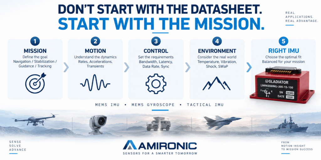
Instead of starting with a product catalog and looking for the MEMS IMU with the best numbers, start with the platform and the mission.
Before selecting a Gyroscope or IMU, determine:
What does the system need to do?
What motion does it need to measure?
What are the typical and maximum dynamics?
Is the primary requirement navigation or closed-loop control?
How much measurement delay can the system tolerate?
At what frequencies does the important motion occur?
And what happens during the most extreme events in the mission profile?
Only after answering these questions do specifications such as the following gain their proper meaning:
Bias Instability, ARW, Noise Density, Bandwidth, Data Rate, Latency, Angular Rate Range, and Acceleration Range.