flagעברית
flagEnglish
3 Rabinovich St., Petah-Tikva, Israel
+972 3 9047744
office@amironic.co.il
Facebook
Twitter
LinkedIn
YouTube
  • Products
    • MEMS Inertial
      • MEMS Gyroscopes
      • Inertial Measurement Units
      • MEMS Accelerometers
      • Inertial Navigation
      • AHRS
    • Circuit Breakers
      • Airpax Circuit Breakers
      • Electronic Circuit Breakers
      • Aircraft Circuit Breakers
      • Thermal Circuit Breakers
      • Sealing Solutions & Guards
    • Footswitches
      • Pedals & Bellows
      • USB
      • Air Switches
      • Medical
      • Modular Bases System
      • Industrial
      • Foot Potentiometers
      • Wireless
    • Mechanical & Transmissions
      • Gears
      • Sealing Solutions
      • Gearboxes
      • Couplings
      • Shafts & Bearings
      • Fasteners
      • Mechanical & Springs
      • Linear Motion
      • Anti-Vibration
    • Sensors
      • Thermostats
      • Temperature
      • Position
      • Pressure
      • Speed
      • Level Sensor
      • Load Cells
      • Flex Sensors
      • Membrane Potentiometer
    • Motors
      • Geared DC
      • Brushless DC
      • Step Motors with Gearbox
      • Torque Motors & Brushless Servo
      • DC Motors
    • Electronics
      • Xenon & IR Lamps
      • Counters & Meters
      • Microelectronics Packaging
      • Waterproof Switches
      • Micro Switches
    • Hand Control
      • Operator Controls (JOYSTICK)
      • Electrical
      • Pneumatic (Medical)
      • USB Hand Control
      • Air Push Button
      • Pressure Switch
      • IR Switch
    • Power Solutions
      • Rugged & Military Power Supply
      • Input Power Protection
      • Sealed Military Power Adaptor
      • Triple Output Military Power Supply Series – up to 250 W
    • Materials
      • Molybdenum and Advanced Alloys (TZM, MOLA, HCT)
      • Tungsten (Wolfram) and Advanced Alloys – High-Performance Materials for Extreme Conditions
      • Materials for Gears
  • Shop
  • Companies
  • About Amironic
  • News
  • Contact
Product was added to your cart

Cart

waze

How to Choose a High-Precision IMU for GPS-Denied Navigation: An Engineering Guide Featuring Gladiator Technologies

MEMS Inertial09/11/2026amironicLTD

Navigation systems operating without reliable GPS signals face a critical engineering challenge: How can a platform maintain accurate estimates of its position, velocity, and orientation when satellite-based navigation is unavailable?

For military platforms, unmanned aerial vehicles (UAVs), robotic systems, and autonomous applications, GPS outages are more than an occasional inconvenience. Intentional jamming, signal spoofing, physical obstruction, and operations in GNSS-challenged environments can all compromise satellite navigation, making reliable inertial sensing an essential part of mission-critical system design.

At the heart of these capabilities is the Inertial Measurement Unit (IMU).

However, not all IMUs deliver the same level of performance in GPS-denied environments. Differences in gyroscope noise, bias stability, accelerometer accuracy, and calibration characteristics can significantly influence how navigation errors accumulate over time.

This is where advanced MEMS inertial technology becomes particularly valuable. Gladiator Technologies has developed a portfolio of high-performance inertial sensors and IMUs designed to address demanding requirements for precision, stability, low latency, and compact system integration.

Nevertheless, one fundamental limitation must be understood: An IMU does not measure position directly, and even the most accurate IMU cannot completely eliminate navigation drift over time without an external reference or aiding source.

In this engineering guide, we examine the key parameters affecting inertial navigation accuracy, explain how small sensor errors develop into position errors, and provide practical guidance for selecting the right IMU based on mission duration, environmental conditions, platform dynamics, and required navigation performance.

We also explore the technological evolution of Gladiator Technologies’ LandMark IMU family, from the SX2-based LandMark 005 to the next-generation SX3-based LandMark 006, and the LandMark 008 currently under development, which is designed to introduce further advances in gyroscope and accelerometer performance.


1. What Is GPS-Denied Navigation, and Why Does It Require a High-Precision IMU?

1.1 Understanding GPS-Denied Navigation

GPS-Denied Navigation refers to the ability to maintain navigation capabilities when reliable positioning information from the Global Positioning System (GPS) is unavailable.

The broader term GNSS-Denied Navigation also covers environments where other satellite navigation systems, including Galileo, GLONASS, and BeiDou, cannot provide dependable positioning information.

Under normal operating conditions, a GNSS receiver provides measurements that allow a navigation system to estimate position and velocity relative to an external reference.

When these measurements are available and trustworthy, they can be used to correct or constrain errors accumulating within an inertial navigation system.

However, when satellite signals become unavailable or unreliable, the navigation system must rely on alternative sources of motion and positioning information.

One of the most important technologies supporting this capability is inertial navigation, which estimates platform motion using angular rate and acceleration measurements.

Unlike satellite-based positioning, inertial sensing does not require continuous reception of external navigation signals.

This makes high-performance IMUs particularly valuable for defense, aerospace, autonomous vehicles, and other mission-critical applications where navigation continuity is essential.

Gladiator Technologies’ advanced MEMS IMUs are designed to provide precise, high-rate inertial measurements that can serve as a foundation for navigation, stabilization, and control systems operating under demanding conditions.

However, while inertial navigation enables continued operation without satellite signals, it cannot independently eliminate the measurement errors that accumulate over time.

1.2 How Does an Inertial Navigation System Work?

A typical six-axis IMU contains:

  • Three gyroscopes, measuring angular velocity around the three measurement axes.
  • Three accelerometers, measuring specific force along those axes.

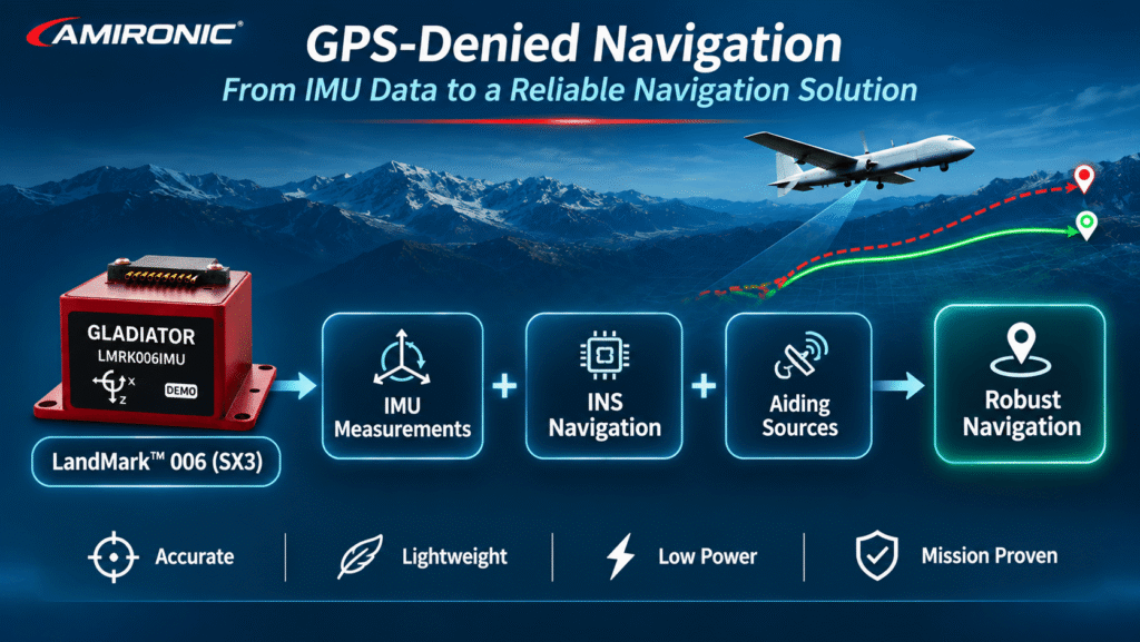
These measurements are processed by an Inertial Navigation System (INS) to estimate the platform’s motion and navigation state.

The calculation generally involves three fundamental stages.

Stage 1 – Attitude Estimation

The navigation system integrates angular rate measurements from the gyroscopes to estimate changes in platform orientation over time.

This process enables continuous tracking of attitude, including Roll, Pitch, and Yaw.

Accurate gyroscope measurements are particularly important because errors in attitude estimation can influence subsequent velocity and position calculations.

This is one of the areas where the low-noise gyroscope technology developed by Gladiator Technologies can provide significant engineering value.

Stage 2 – Velocity Estimation

Accelerometer measurements are transformed from the sensor coordinate frame into the navigation coordinate frame.

After accounting for gravity and other factors required by the navigation model, the system integrates the resulting acceleration to estimate velocity.

The accuracy of this calculation depends on both accelerometer performance and the accuracy of the estimated platform attitude.

Stage 3 – Position Estimation

The navigation system integrates the estimated velocity to calculate changes in position over time.

Unlike GNSS positioning, this calculation does not provide an independent measurement of absolute location.

Instead, the INS continuously propagates the navigation solution based on inertial measurements and known initial conditions.

The engineering implication is important: Position is not measured directly by the IMU. It is calculated through a sequence of mathematical operations that depend on sensor accuracy and initial navigation conditions.

Consequently, even small errors in angular rate or acceleration measurements can propagate through the navigation calculations and affect the overall navigation solution.

For this reason, selecting a high-performance IMU is a critical step in developing a robust inertial navigation architecture.

1.3 Why Do Gyroscope Errors Affect Position Accuracy?

One of the most important principles of inertial navigation is the relationship between attitude accuracy and acceleration estimation.

Consider an aircraft equipped with an inertial navigation system.

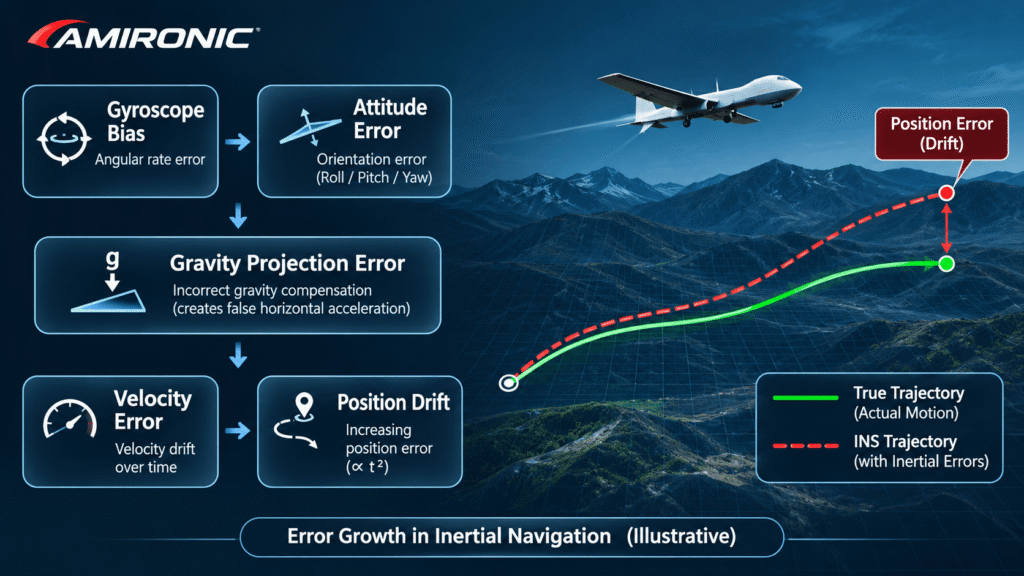
If the gyroscope measurements introduce a small error in the estimated Pitch or Roll angle, the navigation system may transform the accelerometer measurements into the navigation coordinate frame using an incorrect orientation.

Because the navigation calculations must also account for gravity, even a small attitude error can cause part of the gravitational acceleration to be incorrectly interpreted as horizontal acceleration.

For example, an attitude error of just 0.1° can introduce an apparent horizontal acceleration error of approximately 0.017 m/s² due to incorrect gravity projection.

If this error remains constant for 10 seconds without external correction, it could produce approximately:

  • 0.17 m/s of velocity error
  • 0.85 meters of position error

This is a simplified theoretical example. It does not account for all sensor errors, platform dynamics, navigation algorithms, or potential correction mechanisms.

Nevertheless, it demonstrates a fundamental engineering principle:

Gyroscope accuracy affects more than angular measurements. It can also influence the accuracy of calculated velocity and position.

This relationship explains why improvements in gyroscope noise and bias stability are so valuable in high-performance inertial systems.

Gladiator Technologies’ transition from SX2 to SX3 technology represents an important advancement in this area, with the LandMark 006 offering substantially improved gyroscope performance compared with the earlier LandMark 005 generation.

These improvements provide system designers with a more precise inertial measurement foundation for demanding navigation and stabilization applications.

1.4 IMU vs. INS: Understanding the Difference

When designing a GPS-denied navigation system, it is essential to distinguish between two terms that are sometimes incorrectly used interchangeably.

IMU – Inertial Measurement Unit

An IMU measures angular velocity and specific force using gyroscopes and accelerometers.

Depending on the product and interface, the output may include internally calibrated, compensated, and processed measurements.

High-performance IMUs, such as Gladiator Technologies’ LandMark family, are engineered to deliver precise inertial measurements with characteristics suited to demanding navigation, stabilization, and control applications.

INS – Inertial Navigation System

An INS uses inertial measurements, known initial conditions, and navigation algorithms to estimate attitude, velocity, and position.

An INS may also integrate additional sensors or external references to correct accumulated errors and improve navigation reliability.

This distinction is particularly important when evaluating inertial products.

An IMU with excellent noise performance and bias stability can provide a strong foundation for an accurate navigation system. However, the final navigation performance also depends on the INS algorithms, initialization accuracy, sensor error models, mission conditions, and available aiding sources.

The key takeaway for system designers is clear: Selecting an IMU for GPS-denied navigation should begin with the performance requirements of the complete navigation system—not simply a comparison of individual sensor specifications.

With its continued investment in advanced MEMS technology, low-noise gyroscopes, and high-speed inertial data processing, Gladiator Technologies offers engineers a compelling range of IMU solutions for applications where precision, reliability, and navigation continuity matter.
2. How Gyroscope Noise and Bias Affect Navigation Drift

One of the most critical factors when selecting an IMU for GPS-denied navigation is its ability to support accurate attitude estimation over time.

When external positioning updates are unavailable, errors in angular rate measurements can accumulate, affecting not only orientation but also the calculated velocity and position of the platform.

Two of the most important gyroscope performance parameters are Angle Random Walk (ARW) and Gyroscope Bias Stability.

Gladiator Technologies specializes in advanced MEMS inertial technology, developing low-noise, high-stability gyroscopes and IMUs for demanding navigation, stabilization, and control applications.

The company’s transition from SX2 to its next-generation SX3 technology demonstrates how significant improvements in gyroscope performance can provide a more accurate measurement foundation for inertial navigation systems.

2.1 Angle Random Walk (ARW): Why Gyroscope Noise Matters

Angle Random Walk (ARW) describes the accumulation of angular uncertainty caused by white noise in gyroscope measurements.

Even when a platform is stationary, a gyroscope produces a small amount of internal measurement noise.

When angular rate measurements are integrated over time to estimate orientation, this noise contributes to increasing uncertainty in the calculated angle.

ARW is typically expressed in °/√hr.

A lower ARW value indicates a smaller contribution from white noise to attitude uncertainty over time.

Under an ideal white-noise model, the relationship can be expressed as:

σθ(t) = ARW × √t

Where:

  • σθ – Standard deviation of angular error, in degrees.
  • ARW – Angle Random Walk coefficient, in degrees per square root of an hour.
  • t – Elapsed time, in hours.

To understand the practical significance of this parameter, consider two generations of Gladiator Technologies’ LandMark IMUs.

LandMark 005 – SX2 Generation

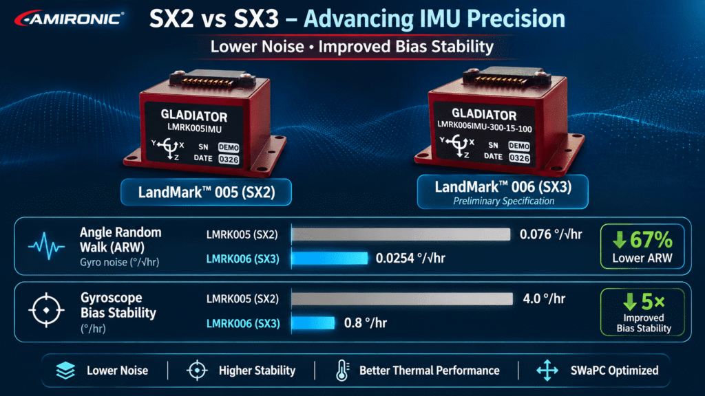
The LandMark 005 is a compact, high-performance MEMS IMU offering low gyroscope noise, with an ARW specification of 0.076°/√hr, according to the SX2 datasheet.

LandMark 006 – Next-Generation SX3 Technology

The LandMark 006 introduces a substantial improvement in gyroscope noise performance.

According to the manufacturer’s preliminary SX3 specifications, the Grade C configuration achieves an ARW of just 0.0254°/√hr.

This represents approximately a 67% reduction in ARW, corresponding to nearly three times lower accumulated angular uncertainty from the white-noise component under the same ideal measurement conditions.

Parameter LandMark 005 – SX2 LandMark 006 – SX3
Gyroscope ARW 0.076°/√hr 0.0254°/√hr
Technology Generation SX2 SX3
Processing Technology VELOX / VELOX Plus VELOX / VELOX Plus
Gyroscope Measurement Range ±490°/s ±300°/s

LandMark 006 values refer to the Grade C configuration and are based on preliminary manufacturer specifications.

This reduction in ARW is particularly valuable in applications requiring precise tracking of small angular movements while maintaining low measurement noise.

For engineers developing advanced navigation and stabilization systems, the SX3 generation provides a compelling improvement in inertial measurement capability.

However, ARW is only one part of the performance equation.

In systems operating without external navigation corrections, gyroscope bias stability is equally important and may become a dominant consideration as mission duration increases.

2.2 Gyroscope Bias Stability: A Key Parameter for Precision Navigation

Gyroscope bias is an offset between the measured angular rate and the actual angular rate.

When this offset is unknown or not fully compensated, the navigation system may interpret part of it as genuine rotational motion.

Over time, this can introduce errors in the estimated platform attitude.

These attitude errors may subsequently affect the transformation of accelerometer measurements into the navigation coordinate frame and the compensation for gravitational acceleration.

Bias Stability describes the stability of the sensor’s bias according to the measurement methodology specified by the manufacturer.

A lower value indicates better stability under the corresponding measurement conditions and can contribute to reducing uncertainty in attitude estimation.

This is another area where Gladiator Technologies’ SX3 generation demonstrates a substantial performance improvement.

According to the manufacturer specifications:

  • LandMark 005 – SX2: Gyroscope Bias Stability of 4°/hr.
  • LandMark 006 – SX3 Grade C: Gyroscope Bias Stability of just 0.8°/hr.

This represents a fivefold improvement in the specified gyroscope bias stability metric.

For designers of precision inertial systems, this is an important advancement.

Improved bias stability can help reduce one of the key contributors to attitude uncertainty, particularly in applications where reliable angular measurements must be maintained over extended periods.

However, an important engineering distinction must be made.

Bias Stability is not equivalent to a constant residual bias error.

It cannot simply be multiplied by mission duration to calculate the actual angular or position error of a navigation system.

Accurate navigation performance predictions require a complete sensor error model, including initialization conditions, noise characteristics, calibration residuals, and navigation algorithms.

Nevertheless, the substantial improvement from 4°/hr to 0.8°/hr highlights the progress achieved through Gladiator Technologies’ SX3 MEMS technology.

2.3 Bias Over Temperature: Maintaining Accuracy in Changing Environments

High-performance inertial systems rarely operate under perfectly controlled laboratory conditions.

Military UAVs, ground vehicles, aerospace platforms, and autonomous systems may experience significant temperature variations throughout their missions.

These changes can influence gyroscope bias and introduce additional measurement errors.

For this reason, engineers must evaluate not only Bias Stability but also Gyroscope Bias Over Temperature.

This parameter describes how the gyroscope bias changes across a specified temperature range, according to the manufacturer’s calibration and testing methodology.

Gladiator Technologies applies calibration and sensor modeling across broad temperature ranges to improve measurement consistency and support compensation under changing environmental conditions.

A comparison of the SX2 and SX3 generations illustrates the importance of this characteristic.

LandMark 005 – SX2

The SX2 datasheet specifies Gyroscope Bias Over Temperature of 0.075°/s, equivalent to 270°/hr.

LandMark 006 – SX3

The preliminary SX3 datasheet specifies Gyroscope Bias Over Temperature of 35°/hr for the Grade C configuration.

When expressed in equivalent units, the reported values indicate a substantial improvement in thermal bias performance.

However, engineers should verify that the measurement conditions, calibration definitions, and test criteria used in the different datasheets are directly comparable before drawing quantitative conclusions about actual navigation performance.

The engineering implication is clear:

Selecting an IMU for demanding operating environments requires more than low noise. Thermal stability, calibration quality, and compensation performance are also essential considerations.

The SX3 generation reflects Gladiator Technologies’ continued focus on improving inertial sensor performance across multiple characteristics rather than optimizing a single specification.

2.4 From SX2 to SX3: What Does the Improvement Mean for GPS-Denied Navigation?

The comparison between LandMark 005 and LandMark 006 demonstrates the technological progress achieved by Gladiator Technologies in precision MEMS inertial sensing.

The following table summarizes several important performance characteristics.

Parameter LandMark 005 – SX2 LandMark 006 – SX3 Grade C
Gyroscope ARW 0.076°/√hr 0.0254°/√hr
Gyroscope Bias Stability 4°/hr 0.8°/hr
Gyroscope Bias Over Temperature 270°/hr 35°/hr
Gyroscope Range ±490°/s ±300°/s
Accelerometer Range ±15g ±15g
Accelerometer Bias Stability 0.020mg 0.020mg

Values are based on the LandMark 005 SX2 datasheet and the preliminary LandMark 006 SX3 datasheet. LandMark 006 specifications refer to Grade C. Bias Over Temperature values have been converted into common units, but identical measurement methodologies should not be assumed.

Three major improvements stand out.

1. Significantly Lower Gyroscope Noise

The reduction in ARW from 0.076°/√hr to 0.0254°/√hr decreases the contribution of white noise to attitude uncertainty.

For systems requiring precise angular measurements, this represents a meaningful improvement in the quality of the inertial data available to the navigation algorithms.

2. Fivefold Improvement in Gyroscope Bias Stability

The reduction in the specified Bias Stability metric from 4°/hr to 0.8°/hr demonstrates the improved stability of Gladiator Technologies’ SX3 gyroscope technology.

This can be particularly valuable when the navigation system must maintain accurate attitude estimates between external aiding updates.

3. Improved Reported Thermal Bias Performance

The reduction in the specified Bias Over Temperature value suggests improved control of temperature-dependent gyroscope bias.

For platforms operating across changing environmental conditions, this characteristic can contribute to more consistent inertial measurements, subject to the applicable calibration and test conditions.

These advancements are particularly relevant to Assured Positioning, Navigation and Timing (APNT) applications, where navigation continuity and resilience are essential even when external positioning sources become unavailable or unreliable.

For engineers evaluating next-generation inertial sensors, Gladiator Technologies’ LandMark 006 represents a significant step forward in gyroscope performance compared with the SX2-based LandMark 005.

Nevertheless, selecting between the two IMUs should not be based on ARW and Bias Stability alone.

Measurement range, platform dynamics, environmental conditions, data interfaces, and complete system requirements must also be considered.

For example, the LandMark 005 offers a wider specified angular rate measurement range of ±490°/s, compared with ±300°/s for the LandMark 006 configuration discussed here.

This difference may influence product selection for applications involving high rotational dynamics.

The engineering advantage of SX3 is clear: Gladiator Technologies delivers a substantially improved gyroscope measurement foundation through lower noise, better bias stability, and improved reported thermal characteristics.

However, the ultimate accuracy of a GPS-denied navigation solution still depends on the complete INS architecture and how effectively it uses the high-quality inertial measurements provided by the IMU.

3. Accelerometer Errors: Why Gyroscope Accuracy Alone Is Not Enough

So far, we have examined how gyroscope noise and bias stability influence attitude estimation. However, in an inertial navigation system, gyroscope performance is only part of the equation.

Even when a navigation system maintains highly accurate attitude estimates, errors in accelerometer measurements can still lead to significant velocity and position drift.

The reason is fundamental: an Inertial Navigation System (INS) calculates velocity by integrating acceleration and estimates position through a second integration.

Consequently, unlike a momentary measurement error, a persistent acceleration error can continue affecting the navigation solution throughout the period of operation without external corrections.

This is why Gladiator Technologies develops high-performance MEMS IMUs that combine precision gyroscopes with carefully characterized accelerometers, providing system designers with the inertial measurements required for demanding navigation, stabilization, and autonomous applications.

3.1 Accelerometer Bias: How a Small Offset Becomes a Position Error

Accelerometer bias is an offset between the measured acceleration and the actual value.

When this bias is not fully compensated, the navigation system may interpret it as genuine platform acceleration.

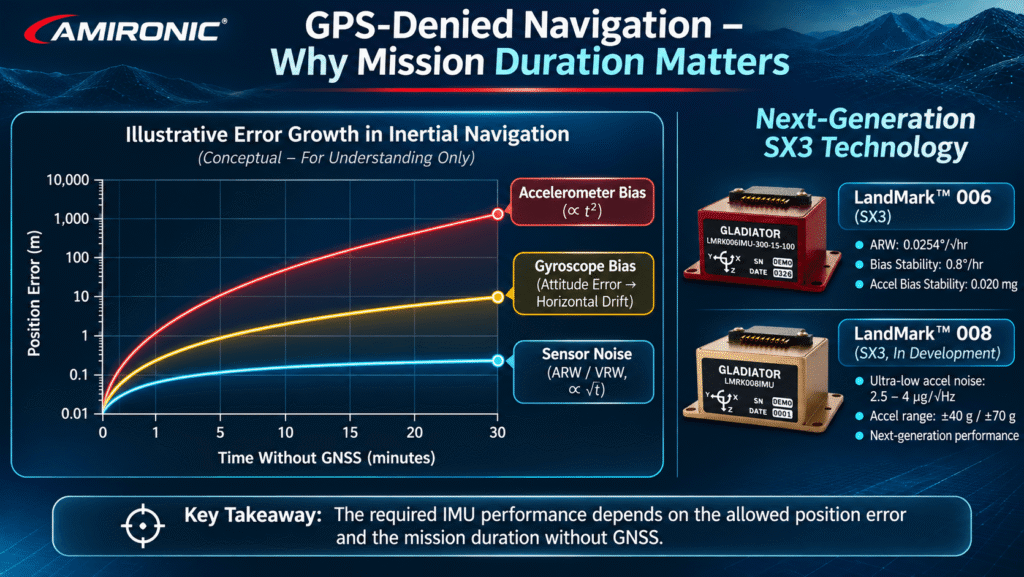
In a simplified model, where acceleration error remains constant and the platform starts with no velocity error, position error develops according to:

Position Error = ½ × Acceleration Error × Time²

In other words, position error increases proportionally to the square of elapsed time.

To illustrate this effect, consider the Gladiator Technologies LandMark 006, an advanced SX3-generation MEMS IMU.

According to the manufacturer’s preliminary specifications, the LandMark 006 accelerometers offer an Accelerometer Bias Stability of 0.020mg, equivalent to 20µg.

To demonstrate the significance of this measurement scale, assume a theoretical constant residual acceleration error of 20µg along a horizontal axis.

This corresponds to approximately 0.000196m/s².

If the error remains constant, without external corrections or additional error sources, the resulting theoretical position errors are:

Elapsed Time Theoretical Position Error
10 seconds Approximately 1cm
30 seconds Approximately 8.8cm
60 seconds Approximately 35cm
120 seconds Approximately 1.41m
300 seconds Approximately 8.83m

Important engineering note: An Accelerometer Bias Stability specification of 20µg does not necessarily represent a constant residual bias of 20µg during an actual mission. This calculation uses that value solely as an illustrative assumption to demonstrate the effect of double integration. It is not a prediction or guarantee of LandMark 006 navigation performance.

In a real navigation system, attitude errors, sensor noise, temperature variations, initialization errors, and navigation algorithm characteristics must also be considered.

Nevertheless, the example illustrates an essential engineering principle:

The longer a navigation system operates without an external reference, the more important it becomes to minimize residual acceleration errors.

For designers evaluating high-performance inertial sensors, this reinforces the importance of considering the complete accelerometer specification rather than focusing exclusively on gyroscope performance.

3.2 Velocity Random Walk (VRW): Understanding Accelerometer Noise

Just as gyroscopes are characterized by Angle Random Walk (ARW), accelerometers also exhibit measurement noise.

One of the key parameters used to describe its effect is Velocity Random Walk (VRW).

VRW characterizes the accumulation of velocity uncertainty resulting from white noise in accelerometer measurements.

Lower accelerometer noise reduces the contribution of this noise to uncertainty in the calculated velocity.

According to the preliminary LandMark 006 specifications, the accelerometer noise density is:

40µg/√Hz, approximately equivalent to 0.0235m/s/√hr in VRW.

This low-noise measurement capability is valuable in applications requiring precise acceleration information, including advanced stabilization systems, inertial navigation, and autonomous platforms.

Gladiator Technologies’ LandMark 006 combines this accelerometer performance with the improved gyroscope characteristics of the SX3 generation, offering engineers a compact inertial sensing solution for demanding system architectures.

However, it is important to distinguish between VRW and accelerometer bias.

White noise introduces statistical uncertainty that increases over time, while a persistent residual bias may create a systematic error.

Both mechanisms can affect navigation performance, but they behave differently and must be evaluated separately.

For GPS-denied navigation, selecting an IMU requires careful consideration of both accelerometer noise and bias characteristics—not simply choosing the sensor with the lowest advertised noise figure.

3.3 Why Better Gyroscopes Do Not Automatically Guarantee Better Position Accuracy

The comparison between Gladiator Technologies’ LandMark 005 and LandMark 006 illustrates an important engineering consideration.

The transition from SX2 to SX3 technology delivers substantial improvements in gyroscope performance, particularly in Angle Random Walk and Gyroscope Bias Stability.

However, according to the respective manufacturer specifications, both products report an Accelerometer Bias Stability of 0.020mg.

This means that improvements in gyroscope performance do not necessarily correspond to equivalent improvements in every accelerometer parameter.

The distinction matters because different navigation systems are limited by different error sources.

In a system where attitude estimation errors dominate the navigation error budget, the improved gyroscope performance of LandMark 006 may provide significant engineering value.

In contrast, when accelerometer errors are the primary limiting factor, improving gyroscope performance alone may deliver a smaller overall benefit.

This is precisely why IMU selection should be based on a complete Navigation Error Budget.

Gladiator Technologies’ expanding LandMark portfolio gives system designers the opportunity to evaluate different combinations of gyroscope performance, accelerometer characteristics, measurement ranges, and system-level requirements.

The objective is not simply to select the newest IMU, but to identify the inertial measurement solution best aligned with the application’s dominant error sources.

3.4 LandMark 008: The Next Step in Advanced Accelerometer Technology

One of the most interesting developments in Gladiator Technologies’ LandMark family is the LandMark 008, an SX3-generation IMU currently under development.

While LandMark 006 demonstrates major improvements in gyroscope performance, LandMark 008 is designed to introduce a new generation of open-loop MEMS accelerometers, targeting substantially lower accelerometer noise and wider measurement ranges.

According to Gladiator Technologies’ 2026 capabilities overview, the preliminary LandMark 008 specifications include:

  • Accelerometer ranges: ±40g and ±70g.
  • Accelerometer noise density: 2.5–4µg/√Hz.
  • Accelerometer Bias Stability: 120–180µg.
  • Planned advances in gyroscope stability and noise performance.

Compared with the 40µg/√Hz accelerometer noise density specified for LandMark 006, the preliminary LandMark 008 values indicate a potential 10× to 16× reduction in accelerometer noise density.

This is a significant advancement in the noise specification, particularly for applications requiring high-resolution acceleration measurements.

Such characteristics may be attractive for advanced stabilization, high-dynamic motion sensing, and other applications where low accelerometer noise and extended measurement range are important.

However, lower noise should not be confused with improved bias stability.

The preliminary Accelerometer Bias Stability values of LandMark 008 are higher than the corresponding value specified for LandMark 006.

Therefore, it would be incorrect to assume that LandMark 008 offers superior performance in every accelerometer accuracy parameter or necessarily produces lower position drift in a navigation system.

The wider acceleration ranges may also make LandMark 008 suitable for platforms experiencing higher dynamic loads, provided that the selected configuration meets the application’s accuracy and measurement requirements.

LandMark 008 highlights Gladiator Technologies’ continued innovation in MEMS inertial sensing: combining advanced SX3 gyroscope technology with a new generation of low-noise, wide-range accelerometers.

As the product remains under development, all specifications presented here are preliminary and subject to change.


4. Mission Duration: The Critical Factor in Determining Required IMU Accuracy

One of the most important variables when selecting an IMU for GPS-denied navigation is how long the system must operate without external navigation corrections.

A system required to maintain inertial navigation for a few seconds may have very different performance requirements from one expected to operate for several minutes without GNSS updates.

As the period without external reference information increases, sensor errors, initialization uncertainty, and navigation algorithm limitations become increasingly important.

This is where selecting the right combination of gyroscope accuracy, accelerometer performance, calibration quality, and data processing capability becomes essential.

Gladiator Technologies’ LandMark IMU family provides engineers with multiple performance options, enabling sensor selection based on actual mission requirements rather than a single specification.

4.1 Short-Duration Inertial Navigation

For applications requiring navigation continuity over relatively short periods, important considerations may include:

  • Low gyroscope noise.
  • Accurate accelerometer measurements.
  • Sufficient bandwidth for platform dynamics.
  • Low data latency.
  • Precise synchronization between the inertial sensors and the control or navigation system.

In these applications, compact high-performance IMUs such as Gladiator Technologies’ LandMark 005 and LandMark 006 can provide a strong foundation for accurate inertial measurements.

The LandMark 006, featuring next-generation SX3 gyroscope technology, is particularly attractive where reduced angular measurement noise and improved bias stability are important design objectives.

However, suitability for a specific navigation requirement still depends on the allowable error, platform dynamics, and mission conditions.

4.2 Longer-Duration Inertial Navigation

When a navigation system must operate for extended periods without GPS, additional sensor and system characteristics become increasingly significant.

Long-Term Bias Behavior

Changes in gyroscope or accelerometer bias can introduce accumulating errors that cannot be eliminated through integration alone.

For this reason, bias characteristics must be evaluated as part of the complete inertial sensor error model.

Thermal Stability

Temperature variations during a mission may influence sensor measurements even after factory calibration.

Gladiator Technologies’ emphasis on calibration and temperature compensation is particularly relevant to applications operating across demanding environmental conditions.

Initialization Accuracy

Initial errors in attitude, velocity, or position can influence the navigation solution throughout the mission.

Even a high-performance IMU cannot independently correct an inaccurate initial position.

Sensor Error Modeling

Advanced inertial navigation algorithms must account for measurement noise, bias behavior, scale factor errors, and sensor-axis misalignment.

Accurate characterization of these parameters is essential when evaluating the expected performance of an INS.

External Aiding Sources

Integrating additional measurements can help constrain navigation errors, depending on the quality and availability of the aiding information.

Possible sources include velocity sensors, vision-based navigation systems, and other independent positioning or motion references.

High-quality inertial measurements remain important because they support continuous state propagation between external updates.

4.3 How Long Can an IMU Navigate Without GPS?

One of the most common questions engineers ask is:

How long can a particular IMU maintain accurate navigation without GPS?

There is no universal answer.

Navigation performance depends on the complete system architecture, not the IMU specification alone.

Two platforms using exactly the same IMU may exhibit very different navigation accuracy due to differences in initialization, motion dynamics, navigation algorithms, environmental conditions, and available aiding sources.

For example, a system relying entirely on inertial measurements will experience different error accumulation characteristics from a system that also incorporates velocity measurements, visual navigation, or other non-GNSS positioning information.

Therefore, it is not technically appropriate to guarantee a specific GPS-denied navigation duration based solely on ARW and Bias Stability values.

The correct engineering approach is to:

  1. Define the maximum allowable position, velocity, and attitude errors.
  2. Establish the required operating duration without GNSS.
  3. Develop a sensor and navigation error budget.
  4. Simulate the expected navigation performance under representative mission conditions.
  5. Select an IMU whose characteristics support the overall system requirements.

The goal is not to select the IMU with the most impressive individual datasheet specification. It is to choose the IMU that enables the complete navigation system to meet its performance requirements under real mission conditions.

With the evolution from LandMark 005 to LandMark 006 and the development of LandMark 008, Gladiator Technologies continues to expand the range of high-performance MEMS inertial solutions available to engineers designing next-generation navigation, stabilization, and autonomous systems.

5. How to Choose the Right IMU for GPS-Denied Navigation

Now that we have examined the effects of gyroscope noise, bias stability, accelerometer errors, and mission duration, we can address the central engineering question: How do you select the right IMU for your navigation system?

Choosing an IMU for GPS-denied navigation involves much more than comparing a single specification on a datasheet.

An inertial navigation system must account for measurement noise, calibration errors, temperature variations, platform dynamics, and timing requirements.

Engineers must also consider size, weight, power consumption, and compatibility with the navigation computer.

Gladiator Technologies’ LandMark IMU family provides a range of advanced MEMS inertial sensing solutions, enabling engineers to select the combination of performance characteristics that best matches their application.

From the established SX2 generation to the advanced SX3 architecture, Gladiator Technologies continues to develop inertial technology designed for demanding navigation, stabilization, and control applications.

5.1 Comparing Gladiator Technologies LandMark 005, LandMark 006, and LandMark 008

The LandMark 005, LandMark 006, and LandMark 008 represent different stages in the evolution of Gladiator Technologies’ MEMS inertial technology.

Each model offers a distinct combination of gyroscope performance, accelerometer characteristics, measurement ranges, and system-level capabilities.

LandMark 005 – Proven SX2 Technology

The LandMark 005 is a compact, six-axis MEMS IMU designed for applications including precision stabilization, flight control, and short-duration inertial navigation.

It combines low-noise gyroscopes and accelerometers with calibration across a broad temperature range and support for Gladiator Technologies’ VELOX processing technology.

Its compact design and high-speed data capabilities make it an attractive solution for applications requiring reliable inertial measurements in space-constrained platforms.

LandMark 006 – Advanced SX3 Gyroscope Performance

The LandMark 006 represents a significant advancement in Gladiator Technologies’ inertial sensing technology.

Built around the next-generation SX3 architecture, it is designed to deliver substantially improved gyroscope performance compared with the SX2 generation.

Key improvements include:

  • Lower Angle Random Walk (ARW).
  • Improved Gyroscope Bias Stability.
  • Reduced temperature-dependent gyroscope bias.

These characteristics make LandMark 006 particularly interesting for engineers developing high-precision navigation, stabilization, and Assured Positioning, Navigation and Timing (APNT) systems.

The manufacturer identifies the LandMark 006 as a solution for demanding applications where accurate inertial measurements and consistent performance are essential.

LandMark 008 – The Next Step in MEMS Inertial Innovation

Currently under development, the LandMark 008 is designed to combine advanced SX3 gyroscope technology with a new generation of open-loop MEMS accelerometers.

The planned design targets wider acceleration measurement ranges and exceptionally low accelerometer noise, alongside multiple angular rate measurement options.

These characteristics may make LandMark 008 especially attractive for future high-dynamic applications requiring both wide measurement ranges and high-resolution acceleration sensing.

LandMark IMU Performance Comparison

Parameter LandMark 005 LandMark 006 LandMark 008
Technology Generation SX2 SX3 SX3
Gyroscope ARW 0.076°/√hr 0.0254°/√hr 0.036°/√hr
Gyroscope Bias Stability 4°/hr 0.8°/hr 0.8°/hr
Gyroscope Range ±490°/s ±300°/s ±300 / ±490 / ±1000 / ±2000°/s
Accelerometer Range ±15g ±15g ±40g / ±70g
Accelerometer Noise 50µg/√Hz 40µg/√Hz 2.5–4µg/√Hz
Accelerometer Bias Stability 20µg 20µg 120–180µg
Processing Technology VELOX / VELOX Plus VELOX / VELOX Plus VELOX Plus – per manufacturer overview
Product Status Existing Product Preliminary Specifications Under Development

Specifications are based on the LandMark 005 SX2 datasheet, the preliminary LandMark 006 SX3 datasheet, and Gladiator Technologies’ 2026 capabilities overview. LandMark 006 values refer to the Grade C configuration. LandMark 008 specifications are preliminary and subject to change.

An important distinction should be emphasized: LandMark 008 is not necessarily superior to LandMark 006 in every performance category.

For example, its preliminary gyroscope ARW value is higher than that of the LandMark 006 Grade C configuration, while its accelerometer noise is substantially lower.

Therefore, these products should not be viewed as a simple progression from good to better to best.

Instead, Gladiator Technologies offers different performance combinations designed to address different engineering requirements.

The advantage for system designers is flexibility: selecting the right balance of noise, stability, dynamic range, and system integration rather than compromising application requirements to fit a single IMU architecture.

5.2 Matching IMU Measurement Range to Platform Dynamics

One of the first parameters engineers should evaluate is the measurement range of the gyroscopes and accelerometers.

If a platform is expected to perform rapid maneuvers or experience high acceleration levels, the IMU must be capable of measuring these conditions without sensor saturation.

For example, the Gladiator Technologies LandMark 006 offers:

  • Gyroscope measurement range of ±300°/s.
  • Accelerometer measurement range of ±15g.

These characteristics may be suitable for applications operating within the corresponding dynamic limits.

In comparison, the LandMark 008 is planned to offer angular rate measurement options up to ±2000°/s, together with accelerometer ranges of ±40g or ±70g.

These extended measurement ranges may be particularly relevant for high-dynamic platforms.

However, a wider measurement range does not automatically guarantee better accuracy.

In some applications, a sensor with a narrower measurement range may provide more suitable noise or stability characteristics.

The correct engineering approach is to match the IMU measurement range to the actual motion profile of the platform, including appropriate design margins.

Gladiator Technologies’ expanding LandMark portfolio allows engineers to evaluate different measurement ranges and performance characteristics according to the specific requirements of their application.

5.3 Bandwidth, Data Rate, and Latency: Why High-Speed Inertial Data Matters

An inertial navigation system must continuously process measurements from its gyroscopes and accelerometers.

Beyond measurement accuracy, the timing and availability of these measurements are also critical.

Three important parameters are:

Bandwidth

Bandwidth defines the frequency range over which the sensor and its processing system can track changes in motion, according to the system’s frequency response.

Data Rate

Data rate determines how frequently inertial measurements are delivered to the external navigation or control system.

Digital Message Delay

Digital Message Delay describes the time between a sensor measurement and the availability of the corresponding data at the interface, according to the manufacturer’s measurement definition.

To address demanding high-speed applications, Gladiator Technologies developed its VELOX and VELOX Plus processing technologies, targeting high data rates, wide bandwidth, and exceptionally low message delays.

According to the LandMark 006 specifications:

Parameter VELOX VELOX Plus
Data Rate Up to 8kHz Up to 10kHz
External Sync Up to 8kHz Up to 10kHz
Maximum Bandwidth 270Hz 600Hz
Digital Message Delay 60µs 20µs

These specifications highlight an important advantage of Gladiator Technologies’ approach to inertial sensing.

VELOX Plus combines data rates of up to 10kHz, bandwidth of up to 600Hz, and digital message delay as low as 20 microseconds.

For engineers designing high-dynamic navigation and control systems, these characteristics can be particularly valuable.

Accurate measurements delivered too late may reduce the quality of state estimation and affect control performance.

Low-latency inertial data can help navigation and control algorithms respond more effectively to rapidly changing platform motion.

However, a higher data rate does not automatically translate into greater navigation accuracy.

System designers must also consider effective bandwidth, synchronization, timestamps, algorithm quality, and the processing capabilities of the navigation computer.

Gladiator Technologies’ VELOX technology provides a strong foundation for high-speed inertial data acquisition, but overall system performance still depends on proper integration and processing.

5.4 SWaP-C: High-Performance Inertial Sensing in Compact Platforms

For aerospace, unmanned, and mobile systems, IMU selection is influenced not only by sensor accuracy but also by physical integration constraints.

The term SWaP-C refers to:

  • Size – Physical dimensions and volume.
  • Weight – Total sensor mass.
  • Power – Electrical power consumption.
  • Cost – Overall solution cost.

Even an IMU with excellent measurement performance may be unsuitable if it is too large, too heavy, or exceeds the platform’s available power budget.

This is particularly important in UAVs, compact robotic systems, and other applications where every gram and cubic inch matters.

Gladiator Technologies’ LandMark 005 and LandMark 006 offer high-performance inertial sensing in exceptionally compact packages.

According to the manufacturer specifications:

  • LandMark 005: Approximately 0.6 cubic inches in volume and 19 grams in weight.
  • LandMark 006: Approximately 0.63 cubic inches in volume and 17 grams in weight.

The LandMark 008, currently under development, is planned to use a larger package with a volume below 1.5 cubic inches and a weight not exceeding 50 grams, according to preliminary data.

These differences demonstrate the importance of balancing sensor performance with platform integration requirements.

For applications requiring compact dimensions and improved gyroscope accuracy, LandMark 006 may offer a particularly attractive combination.

For future applications requiring wider acceleration ranges and exceptionally low accelerometer noise, LandMark 008 may provide additional design options.

Gladiator Technologies’ LandMark family enables engineers to evaluate inertial performance alongside SWaP-C constraints, supporting more effective integration into demanding aerospace, defense, and autonomous platforms.


6. Engineering Case Study: Selecting a Gladiator Technologies IMU for a UAV Operating in a GPS-Denied Environment

Consider a representative engineering scenario involving an unmanned aerial vehicle (UAV) that must continue operating when GNSS reception becomes unavailable or unreliable.

This example illustrates the IMU selection process and does not represent a specific Gladiator Technologies customer project or a documented field test.

6.1 Defining the Navigation Requirements

The UAV navigation architecture includes a GNSS receiver, an IMU, and a navigation computer.

During operation, GNSS reception may be temporarily interrupted due to signal interference, environmental conditions, or other factors.

The navigation system must continue estimating the platform’s attitude, velocity, and position until a reliable external reference becomes available again or alternative aiding information can be used.

The key engineering requirements include:

  • Continuous availability of inertial motion measurements.
  • Reduced accumulation of attitude estimation errors.
  • Measurement ranges suitable for expected maneuvers and acceleration levels.
  • Low data latency.
  • Compact size and weight appropriate for the UAV platform.
  • Reliable operation across a broad temperature range.

These requirements provide the basis for evaluating different IMUs within the Gladiator Technologies LandMark family.

6.2 Evaluating LandMark 005: Compact and Proven SX2 Performance

The Gladiator Technologies LandMark 005 may be suitable for UAV applications requiring compact, low-noise inertial sensing with support for high-speed data interfaces.

The unit offers:

  • Gyroscope measurement range of ±490°/s.
  • Accelerometer measurement range of ±15g.
  • Low-noise MEMS inertial sensing.
  • Support for VELOX processing technology.

These characteristics may make LandMark 005 a suitable option for platforms operating within its specified measurement ranges, subject to a detailed analysis of the expected motion dynamics.

However, when the navigation error budget requires further reductions in gyroscope noise or improved bias stability, the next-generation SX3 architecture deserves closer consideration.

6.3 Evaluating LandMark 006: The SX3 Advantage

The Gladiator Technologies LandMark 006 introduces significant improvements in gyroscope performance compared with LandMark 005.

Two specifications are particularly noteworthy:

  • Gyroscope ARW: Reduced from 0.076°/√hr to 0.0254°/√hr.
  • Gyroscope Bias Stability: Improved from 4°/hr to 0.8°/hr.

These improvements can reduce important sources of uncertainty in attitude estimation.

In a UAV navigation system where gyroscope errors represent a significant portion of the navigation error budget, the improved SX3 gyroscope performance may provide meaningful engineering benefits.

The LandMark 006 also supports VELOX Plus, enabling high data rates and low message delays, depending on configuration.

These capabilities can be valuable in applications requiring rapid inertial measurements and precise timing.

For compact UAV platforms, LandMark 006 combines advanced gyroscope performance with a lightweight package of approximately 17 grams.

However, its specified angular rate range of ±300°/s must be evaluated against the UAV’s maximum expected rotational rates.

For applications prioritizing improved attitude measurement accuracy in a compact form factor, LandMark 006 represents a compelling evolution of Gladiator Technologies’ MEMS IMU technology.

6.4 Evaluating LandMark 008: Future Potential for High-Dynamic Applications

If the UAV is expected to experience higher acceleration levels, or if substantially lower accelerometer noise is required, the LandMark 008 may become an interesting option as its development progresses.

The planned design combines SX3 gyroscope technology with a new generation of low-noise, open-loop MEMS accelerometers.

Its preliminary specifications include wider acceleration measurement ranges and significantly reduced accelerometer noise density.

These characteristics may be valuable for high-dynamic platforms or applications requiring high-resolution acceleration measurements.

However, LandMark 008 remains under development, and its specifications should be treated as preliminary.

Furthermore, accelerometer Bias Stability must be evaluated independently.

Lower accelerometer noise does not necessarily guarantee better overall navigation accuracy or lower position drift.

6.5 Case Study Conclusions: Selecting the Right LandMark IMU

This example demonstrates why selecting an IMU for GPS-denied UAV navigation requires a system-level approach.

When improved attitude measurement performance is a primary requirement and compact size is essential, LandMark 006 may offer significant advantages over the earlier SX2 generation.

When wider acceleration measurement ranges or substantially lower accelerometer noise are the dominant requirements, the future LandMark 008 may provide additional opportunities.

LandMark 005 remains a relevant option where its combination of measurement range, noise performance, and compact integration meets the application’s needs.

In every case, final selection requires an evaluation of the complete navigation system, including its error budget, dynamics, environmental conditions, and available aiding sources.

The key engineering principle is not to choose the newest IMU automatically, but to select the Gladiator Technologies inertial solution whose performance characteristics best address the dominant error sources and mission requirements.

With its continued development of SX3 MEMS technology, advanced LandMark IMUs, and high-speed VELOX processing, Gladiator Technologies provides system designers with an expanding portfolio of precision inertial sensing solutions for demanding navigation, stabilization, and autonomous applications.

7. What an IMU Alone Cannot Solve in GPS-Denied Navigation

One of the most important considerations when designing a GPS-denied navigation system is understanding that even an exceptionally accurate IMU is not a complete navigation solution on its own.

Advanced inertial sensors such as the Gladiator Technologies LandMark 005 and LandMark 006 deliver precise, low-noise measurements with stability characteristics suitable for demanding navigation, stabilization, and control applications.

However, an IMU measures angular velocity and specific force. It does not directly measure geographic position or ground-relative velocity.

Understanding these limitations is essential when selecting an inertial sensing solution and designing the complete navigation architecture.

7.1 An IMU Does Not Provide Absolute Position

An IMU cannot independently determine the geographic location of a platform.

To calculate position through inertial navigation, an INS requires initial information, including position, velocity, and attitude.

Once initialized, the navigation system uses inertial measurements to estimate changes in the platform’s motion and position.

However, if the initial position is incorrect, IMU measurements alone cannot identify or correct that error.

This distinction is particularly important in applications requiring reliable positioning during extended GNSS outages.

7.2 An IMU Cannot Completely Eliminate Navigation Drift

Even the most advanced low-noise inertial sensors produce measurements containing some level of error.

These errors may originate from:

  • Sensor noise.
  • Gyroscope and accelerometer bias.
  • Temperature-dependent variations.
  • Scale factor errors.
  • Sensor-axis misalignment.

As the navigation system integrates inertial measurements, some of these errors accumulate over time.

Improved sensor performance can reduce important contributors to navigation drift, but it cannot eliminate the underlying phenomenon.

This is why even a next-generation SX3 IMU cannot guarantee unlimited accurate navigation without additional reference information.

The engineering advantage of high-performance Gladiator Technologies IMUs is their ability to provide more accurate inertial measurements, helping system designers reduce selected sources of navigation uncertainty.

7.3 An IMU Cannot Independently Detect GPS Spoofing or Jamming

GPS jamming and GPS spoofing represent two different threats to satellite navigation.

Jamming interferes with the receiver’s ability to acquire or track satellite signals.

Spoofing can cause a receiver to generate incorrect navigation information by introducing misleading signals.

An IMU does not depend on satellite reception to perform its measurements.

Therefore, a Gladiator Technologies IMU can continue providing inertial motion data even when GPS reception is disrupted.

However, an IMU alone cannot necessarily identify the cause of a GNSS failure or independently determine whether a received satellite signal is authentic.

In advanced navigation architectures, the GNSS navigation solution can be compared with inertial motion predictions to identify inconsistencies.

Reliable detection of jamming or spoofing requires appropriate algorithms and, in some cases, additional independent information sources.

7.4 An IMU Is Not a Replacement for an INS

Even when an IMU incorporates advanced calibration, digital signal processing, and high-speed data output, it does not necessarily provide a complete navigation solution.

An INS uses inertial measurements, initial conditions, and navigation algorithms to calculate attitude, velocity, and position.

Therefore, engineers must distinguish between the quality of the measurements delivered by an IMU and the accuracy of the navigation solution generated by the INS.

A precision IMU from Gladiator Technologies provides a critical measurement foundation for GPS-denied navigation, but successful system performance still requires appropriate navigation algorithms, accurate initialization, and external aiding sources when necessary.


8. Sensor Fusion: Integrating IMUs with Additional Navigation Sources

One of the most effective approaches to improving navigation reliability in GNSS-denied environments is to combine measurements from multiple independent sources.

This approach is known as Sensor Fusion.

Rather than relying exclusively on inertial measurements, the navigation system combines information from different sensors to improve state estimation and constrain accumulated errors.

High-performance IMUs play a central role in these architectures because they provide continuous, high-rate motion measurements, including during periods when other navigation sources become unavailable.

8.1 Integrating IMU and GNSS Measurements

When reliable GNSS information is available, it can be used to correct accumulated position and velocity errors in the inertial navigation solution.

When GNSS reception is interrupted, the INS can continue propagating the navigation solution using IMU measurements.

Once trustworthy GNSS information becomes available again, the navigation system can resume combining the two measurement sources.

This approach is widely used in integrated INS/GNSS navigation systems.

However, when GNSS information is suspected of being spoofed, it should not automatically be accepted as a valid correction source.

Gladiator Technologies’ low-noise MEMS IMUs can provide continuous inertial measurements during GNSS interruptions, supporting navigation architectures designed for improved resilience and continuity.

8.2 Combining IMUs with Vision-Based Navigation

Vision-based navigation systems use cameras and image-processing algorithms to estimate platform motion relative to the surrounding environment.

Technologies such as Visual Odometry and Visual-Inertial Odometry (VIO) combine visual information with inertial measurements.

The IMU provides high-rate angular velocity and acceleration measurements, while the vision system can introduce additional constraints on platform motion.

This combination can improve trajectory estimation and help limit certain accumulated navigation errors.

However, vision-based navigation performance depends on lighting conditions, environmental texture, image quality, and platform dynamics.

For applications requiring precise motion tracking, the low-noise gyroscopes and high-speed data interfaces available in Gladiator Technologies’ LandMark family can be valuable components of a visual-inertial architecture.

8.3 Combining IMUs with Velocity and Distance Sensors

Ground vehicles can incorporate velocity measurements from wheel sensors or other independent sources.

Depending on the application, airborne platforms may also use altitude, velocity, or range measurements from additional systems.

These measurements can provide constraints that help reduce uncertainty in the estimated navigation state.

For example, an independent velocity measurement can help constrain some of the velocity errors accumulated through accelerometer integration.

The effectiveness of this approach depends on sensor accuracy, measurement availability, and the navigation algorithm.

8.4 The Value of a High-Precision IMU in Sensor Fusion

Even when a navigation system combines multiple measurement sources, IMU quality remains critically important.

Inertial sensors provide continuous, high-frequency information about platform motion, including during temporary interruptions of external measurements.

Lower gyroscope noise and improved bias stability can improve the quality of motion predictions between external sensor updates.

This is where Gladiator Technologies’ SX3 technology offers an important engineering advantage.

With substantially improved gyroscope ARW and Bias Stability compared with the SX2 generation, the LandMark 006 provides a more precise inertial measurement foundation for demanding sensor-fusion architectures.

However, the actual improvement in the integrated navigation solution also depends on the quality of the other sensors, the sensor error models, and the fusion algorithm.


9. Common Mistakes When Selecting an IMU for GPS-Denied Navigation

9.1 Selecting an IMU Based on ARW Alone

Low Angle Random Walk is an important specification, but it does not describe overall sensor performance.

Selecting an IMU based exclusively on ARW may overlook Bias Stability, temperature-dependent errors, scale factor characteristics, and accelerometer performance.

For example, the Gladiator Technologies LandMark 006 offers a substantial ARW improvement compared with LandMark 005, but the appropriate product must still be selected according to measurement range and system requirements.

9.2 Treating Bias Stability as a Direct Navigation Error

Bias Stability does not necessarily represent a constant residual bias during a mission.

It cannot independently predict position error after several minutes of GPS-denied operation.

Reliable navigation performance estimates require an appropriate error model that accounts for sensor characteristics, initialization, and platform dynamics.

9.3 Ignoring Accelerometer Performance

An inertial navigation system relies on both gyroscopes and accelerometers.

Even with excellent gyroscope performance, acceleration measurement errors can continue to affect velocity and position estimates.

The comparison between LandMark 006 and the preliminary LandMark 008 specifications illustrates why accelerometer noise, Bias Stability, and measurement range must be evaluated independently.

9.4 Choosing the Wrong Measurement Range

An IMU with excellent noise characteristics may still be unsuitable if its measurement range is lower than the expected angular rates or accelerations.

Sensor saturation during a maneuver can significantly degrade the navigation solution.

Engineers should therefore define the platform’s maximum dynamic requirements, including appropriate design margins.

Gladiator Technologies’ LandMark portfolio offers different measurement ranges to support a variety of platform dynamics.

9.5 Overlooking Data Latency and Synchronization

Navigation systems require more than accurate measurements.

They also require reliable information about when those measurements were acquired.

Unknown delays, inaccurate timestamps, or poor synchronization between sensors can introduce additional errors.

High-speed processing technologies such as Gladiator Technologies’ VELOX and VELOX Plus can help address demanding data-rate and latency requirements.

However, proper interface design and system-level synchronization remain essential.

9.6 Assuming a High-Precision IMU Eliminates the Need for External Aiding

One of the most significant misconceptions is that sufficiently accurate inertial sensors can maintain precise GPS-free navigation indefinitely.

In reality, every unaided inertial navigation system experiences error accumulation.

Higher-performance sensors can reduce important sources of drift, but they do not eliminate the need to consider additional reference sources when navigation requirements demand them.


10. Engineering Rules of Thumb for Selecting an IMU for GPS-Denied Navigation

IMU selection should be an integral part of the overall navigation system design process, rather than an isolated decision based on catalog specifications.

The following practical guidelines can help engineers define requirements and evaluate suitable inertial sensing solutions.

10.1 Define the Required GNSS-Outage Duration

Before selecting an IMU, determine how long the navigation system must operate without a reliable satellite reference.

As this duration increases, sensor stability and the system’s ability to constrain accumulated errors become increasingly important.

10.2 Define the Maximum Allowable Position Error

A general requirement for “accurate navigation” is not sufficient.

Engineers should define quantitative limits for position, velocity, and attitude errors, including the required statistical confidence level.

These requirements provide the foundation for a meaningful navigation error budget.

10.3 Evaluate ARW and Bias Stability Together

ARW describes the contribution of gyroscope white noise to angular uncertainty.

Bias Stability describes sensor bias behavior according to the applicable measurement methodology.

Both are important, but they represent different error mechanisms.

Gladiator Technologies’ LandMark 006 demonstrates significant improvements in both parameters compared with the SX2-based LandMark 005, making it an attractive option when gyroscope performance is a key design priority.

10.4 Do Not Overlook Accelerometer Specifications

In addition to gyroscope performance, evaluate accelerometer noise, bias stability, temperature effects, and measurement range.

In some navigation architectures, accelerometer errors may become the dominant limitation on position accuracy.

The LandMark 008 development program highlights Gladiator Technologies’ continued focus on advancing accelerometer technology alongside gyroscope performance.

10.5 Match Measurement Range to Mission Dynamics

Verify that angular rate and linear acceleration ranges are suitable for the expected maneuvers, vibrations, and accelerations.

LandMark 005, LandMark 006, and LandMark 008 offer different measurement range characteristics, making application-specific evaluation essential.

10.6 Evaluate Bandwidth and Latency Requirements

In dynamic systems, data rate, bandwidth, and digital message delay can influence overall system performance.

Ensure that the inertial data interface is compatible with the navigation computer architecture and synchronization requirements.

Gladiator Technologies’ VELOX Plus technology, supporting data rates up to 10kHz and digital message delay as low as 20µs, offers important capabilities for demanding high-speed applications.

10.7 Consider Environmental Conditions

Temperature variations, vibration, shock, and installation conditions can influence inertial sensor performance.

Review the manufacturer’s environmental specifications and confirm compatibility with the intended operating environment.

10.8 Simulate Navigation Performance Before Final Selection

When quantitative navigation requirements are available, perform simulations using appropriate sensor error models and representative mission profiles.

These simulations can help identify dominant error sources and compare different IMU options.

At a later development stage, simulation results should be validated through suitable system-level testing.


11. Frequently Asked Questions (FAQ)

Can an IMU navigate without GPS?

Yes. An Inertial Navigation System (INS) can estimate changes in attitude, velocity, and position using IMU measurements and known initial conditions, without continuous GPS reception.

However, measurement errors accumulate over time, so navigation accuracy cannot be maintained indefinitely without additional references or aiding information.

What is the difference between an IMU and an INS?

An IMU (Inertial Measurement Unit) provides angular velocity and specific force measurements.

An INS (Inertial Navigation System) uses inertial measurements and navigation algorithms to estimate attitude, velocity, and position.

What is the most important IMU specification for GPS-denied navigation?

There is no single specification that determines navigation performance.

Engineers must evaluate ARW, Bias Stability, accelerometer performance, calibration errors, environmental conditions, and mission duration together.

What is the difference between ARW and Bias Stability?

Angle Random Walk (ARW) describes the accumulation of angular uncertainty caused by white noise in gyroscope measurements.

Bias Stability describes the stability of sensor bias under defined measurement conditions.

Both influence sensor performance, but through different error mechanisms.

Does lower ARW guarantee better position accuracy?

Not necessarily.

Lower ARW reduces the white-noise contribution to attitude uncertainty, but position accuracy also depends on accelerometer performance, bias characteristics, initialization, and navigation algorithms.

What are the advantages of Gladiator Technologies LandMark 006 over LandMark 005?

The LandMark 006, based on Gladiator Technologies’ SX3 technology, offers substantial improvements in gyroscope performance compared with the SX2-based LandMark 005.

According to the manufacturer specifications:

  • Gyroscope ARW: Reduced from 0.076°/√hr to 0.0254°/√hr.
  • Gyroscope Bias Stability: Improved from 4°/hr to 0.8°/hr.

These values represent approximately 67% lower ARW and a fivefold improvement in the specified Bias Stability metric.

LandMark 006 values refer to the Grade C configuration and preliminary manufacturer specifications.

Is LandMark 008 more accurate than LandMark 006?

Not necessarily in every performance category.

LandMark 008 is designed to offer exceptionally low accelerometer noise and wider measurement ranges.

However, some of its preliminary ARW and bias specifications differ from those of LandMark 006.

The appropriate selection depends on the application requirements, and LandMark 008 specifications remain preliminary.

Does a 10kHz data rate improve navigation accuracy?

A high data rate can benefit dynamic systems requiring rapid updates and precise synchronization.

However, a higher data rate does not eliminate sensor errors or independently guarantee improved navigation accuracy.

Gladiator Technologies’ VELOX Plus technology provides high-speed inertial data capabilities that can support demanding navigation and control architectures.

How long can LandMark 006 navigate without GPS?

LandMark 006 is an IMU, not a complete INS navigation solution.

A specific GPS-denied navigation duration cannot be determined from the IMU datasheet alone.

Actual performance depends on allowable navigation error, initialization, platform dynamics, navigation algorithms, and available aiding sources.

Can an IMU detect GPS spoofing?

An IMU does not independently determine whether a GPS signal is authentic.

However, inertial measurements can be used within a navigation architecture that compares predicted motion against GNSS information to identify inconsistencies.

Reliable spoofing detection requires suitable algorithms and potentially additional independent information sources.

Is Gladiator Technologies LandMark 006 suitable for APNT applications?

Gladiator Technologies identifies LandMark 006 as a solution intended for applications including Assured Positioning, Navigation and Timing (APNT) and platforms operating in GPS-denied environments.

Its improved SX3 gyroscope performance makes it a relevant candidate for advanced inertial navigation architectures.

However, suitability for a particular system must be evaluated against its accuracy, dynamics, environmental, and navigation architecture requirements.


12. Glossary: GPS-Denied Navigation and IMU Technology

IMU – Inertial Measurement Unit

An inertial sensing device typically containing three gyroscopes and three accelerometers, providing angular velocity and specific force measurements.

INS – Inertial Navigation System

A navigation system that uses inertial measurements to estimate attitude, velocity, and position relative to known initial conditions.

GNSS – Global Navigation Satellite System

The collective term for satellite navigation systems, including GPS, Galileo, GLONASS, and BeiDou.

GPS-Denied Navigation

Navigation under conditions where reliable GPS positioning information is unavailable or cannot be trusted.

APNT – Assured Positioning, Navigation and Timing

A system-level approach intended to improve the availability, reliability, and resilience of positioning, navigation, and timing services under challenging conditions.

Gyroscope

A sensor that measures angular velocity around one or more axes.

Accelerometer

A sensor that measures specific force, which is used in motion estimation and inertial navigation calculations.

ARW – Angle Random Walk

A measure of gyroscope white noise and its contribution to accumulated angular uncertainty through integration.

VRW – Velocity Random Walk

A measure describing how accelerometer white noise contributes to accumulated velocity uncertainty.

Bias

An offset between a sensor’s measured output and the actual physical quantity.

Bias Stability

A measure of sensor bias stability under defined measurement conditions.

Bias Over Temperature

The change in sensor bias across a specified temperature range, according to the applicable testing and calibration methodology.

Scale Factor Error

An error in the relationship between the measured physical quantity and the sensor output.

Misalignment

A difference between the sensor measurement axes and the intended reference coordinate frame.

Dead Reckoning

A navigation method that estimates current position from a known initial state and accumulated motion estimates.

Sensor Fusion

The combination of information from multiple sensors or measurement sources to improve system state estimation.

Allan Deviation

A statistical analysis method used to characterize sensor noise and stability over different averaging times.

SWaP-C – Size, Weight, Power and Cost

A set of physical, electrical, and economic considerations used when selecting components and designing systems.

VELOX / VELOX Plus

Gladiator Technologies’ inertial data processing and interface technologies designed to support high data rates, wide bandwidth, and low latency.

SX2 / SX3

Technology generations of inertial sensors and systems developed by Gladiator Technologies.


13. Conclusion: Choosing the Right IMU Starts with Understanding Navigation Errors

GPS-denied navigation remains one of the most demanding challenges in the design of autonomous systems, defense platforms, and applications operating in environments where GNSS signals are unavailable or unreliable.

A high-precision IMU plays a critical role in maintaining continuous motion estimation when satellite navigation becomes unavailable.

However, navigation accuracy is never determined by a single specification.

Gyroscope noise, bias stability, accelerometer performance, calibration errors, temperature effects, and mission duration all influence the accumulation of attitude, velocity, and position errors.

Gladiator Technologies’ evolution from SX2 to SX3 represents a significant advancement in high-performance MEMS inertial sensing.

The LandMark 006 delivers substantially lower gyroscope ARW and improved Bias Stability compared with the LandMark 005, providing a more advanced measurement foundation for systems requiring precise inertial data.

Meanwhile, the LandMark 008, currently under development, points toward another important technological direction: exceptionally low-noise accelerometers combined with wider measurement ranges and advanced SX3 gyroscope technology.

Together, these developments demonstrate Gladiator Technologies’ continued investment in precision inertial sensing for demanding aerospace, defense, navigation, stabilization, and autonomous applications.

Nevertheless, even the most advanced inertial sensor cannot completely eliminate navigation drift.

Designing a reliable GPS-denied navigation system requires careful consideration of IMU performance, INS algorithms, initialization accuracy, and available external aiding sources.

The key engineering principle is straightforward: A precision IMU cannot replace a well-designed navigation system, but it can significantly improve the quality of the inertial measurements on which that system depends.

Find the Right Gladiator Technologies IMU for Your Application

Amironic Ltd., the representative of Gladiator Technologies in Israel, supports engineers and system designers in selecting high-performance MEMS gyroscopes, accelerometers, and IMUs for demanding applications.

Whether your project requires the compact SX2-based LandMark 005, the improved gyroscope performance of the SX3-based LandMark 006, or an evaluation of next-generation technologies such as LandMark 008, Amironic can assist with technical information and product selection.

Contact Amironic to explore Gladiator Technologies’ inertial sensing solutions and identify the IMU best suited to your navigation, stabilization, or autonomous system requirements.

Part of Our Advanced MEMS Inertial Sensors Engineering Series

This article is part of a seven-part technical series by Amironic, exploring the engineering challenges of modern MEMS inertial sensors and the evolution of Gladiator Technologies’ SX2 and next-generation SX3 technologies.

The series covers sensor noise, bandwidth, latency, gyroscope stability, accelerometer architectures, environmental performance, and precision navigation.

Explore the complete series:

  1. IMU Performance: Noise, Bandwidth and Latency
  2. Allan Deviation: Understanding Noise and Drift
  3. SX2 vs. SX3: The Future of Inertial Sensors
  4. Open-Loop vs. Closed-Loop Accelerometers
  5. How Shock and Vibration Affect IMU Accuracy
  6. Hermetic Sealing: IP67 vs. MIL-STD-883
  7. Selecting an IMU for GPS-Denied Navigation
Tags: Gladiator_Technologies

Related Articles

How Do Shock and Vibration Affect IMU Measurement Accuracy?

03/11/2026amironicLTD

From IMU to INS: How a Tactical Navigation System Is Really Built

16/07/2026amironicLTD

The IMU Was Excellent. The Image Still Shook.

01/06/2026amironicLTD

Recent Posts

  • How to Choose a High-Precision IMU for GPS-Denied Navigation: An Engineering Guide Featuring Gladiator Technologies
  • Vacuum Switches for Filter Monitoring – Clog Detection, Differential Pressure and Predictive Maintenance
  • Hook Terminal vs. Screw Terminal – Understanding Terminal Connections in AIRPAX Hydraulic Magnetic Circuit Breakers
  • Hermetic Sealing in Inertial Sensors – What Is the Difference Between IP67 and MIL-STD-883?
  • Pneumatic Switches for Wet Environments – Operating Principles, Electrical Separation, and Applications in Pools, Spas, and Humid Environments

Categories

  • Air Switch
  • Circuit Breakers
  • Elapsed Time Indicator
  • Feedthrough
  • Footswitches
  • Gears & Transmission
  • Hour Meters
  • Infra Red Switches
  • INFRARED LAMPS
  • Low Noise Inertial MEMS
  • Mechanics
  • MEMS Gyroscope
  • MEMS Inertial
  • Microelectronics
  • Motors
  • Position Sensors
  • Power Supply
  • Pressure Sensors
  • Pressure Switch
  • Sealing
  • Switches
  • Temperature Sensors
  • Tungsten and Molybdenum
  • Uncategorized
  • Vacuum Switches

Quick Contact

Fill out the form and our representatives will return to you

    Name (required)

    Email (required)

    Phone

    Message

    This site is protected by reCAPTCHA and the Google
    Privacy Policy and
    Terms of Service apply.

    Amironic Ltd.

    3 Rabinovich Street, Petah Tikva 4928144 , Israel. Tel: +972-3-9047744 E-mail: office@amironic.co.il
    Email
    Facebook
    Twitter
    LinkedIn
    YouTube
    Press on the ISO Certificate below for download
    ISO 9001:2015 Certification
    • MEMS Inertial
    • Circuit Breakers
    • Footswitches
    • Mechanical & Transmissions
    • Sensors
    • Motors
    • Electronics
    • Hand Control
    • Power Solutions

    News

    • How to Choose a High-Precision IMU for GPS-Denied Navigation: An Engineering Guide Featuring Gladiator Technologies
    • Vacuum Switches for Filter Monitoring – Clog Detection, Differential Pressure and Predictive Maintenance
    • Hook Terminal vs. Screw Terminal – Understanding Terminal Connections in AIRPAX Hydraulic Magnetic Circuit Breakers
    • Hermetic Sealing in Inertial Sensors – What Is the Difference Between IP67 and MIL-STD-883?
    • Pneumatic Switches for Wet Environments – Operating Principles, Electrical Separation, and Applications in Pools, Spas, and Humid Environments
    About AmironicContactעברית
    © 2022 Amironic All rights reserved. All Trademarks are the property of their respective owners.
    • Increase Font
    • Decrease Font
    • Black & White
    • Inverse Colors
    • Highlight Links
    • Regular Font
    • Reset