flagעברית
flagEnglish
3 Rabinovich St., Petah-Tikva, Israel
+972 3 9047744
office@amironic.co.il
Facebook
Twitter
LinkedIn
YouTube
  • Products
    • MEMS Inertial
      • Gyros & Accels
      • IMU
      • Inertial Navigation
      • AHRS
    • Circuit Breakers
      • Airpax Circuit Breakers
      • Electronic Circuit Breakers
      • Aircraft Circuit Breakers
      • Thermal Circuit Breakers
      • Sealing Solutions & Guards
    • Footswitches
      • Pedals & Bellows
      • USB
      • Air Switches
      • Medical
      • Modular Bases System
      • Industrial
      • Foot Potentiometers
      • Wireless
    • Mechanical & Transmisions
      • Gears
      • Sealing Solutions
      • Gearboxes
      • Couplings
      • Shafts & Bearings
      • Fasteners
      • Mechanical & Springs
      • Linear Motion
      • Anti-Vibration
    • Sensors
      • Thermostats
      • Temperature
      • Position
      • Pressure
      • Speed
      • Level Sensor
      • Load Cells
      • Flex Sensors
      • Membrane Potentiometer
    • Motors
      • Geared DC
      • Brushless DC
      • Step Motors with Gearbox
      • Torque Motors & Brushless Servo
      • DC Motors
    • Electronics
      • Xenon & IR Lamps
      • Counters & Meters
      • Microelectronics Packaging
      • Waterproof Switches
      • Micro Switches
    • Hand Control
      • Operator Controls (JOYSTICK)
      • Electrical
      • Pneumatic (Medical)
      • USB Hand Control
      • Air Push Button
      • Pressure Switch
      • IR Switch
    • Power Solutions
      • Rugged & Military Power Supply
      • Input Power Protection
      • Sealed Military Power Adaptor
      • Triple Output Military Power Supply Series – up to 250 W
    • Materials
      • Molybdenum and Advanced Alloys (TZM, MOLA, HCT)
      • Tungsten (Wolfram) and Advanced Alloys – High-Performance Materials for Extreme Conditions
      • Materials for Gears
  • Shop
  • Companies
  • About Amironic
  • News
  • Contact
Product was added to your cart

Cart

waze

You Don’t Always Need to Measure Temperature – Sometimes You Just Need to Know When to Stop

Temperature Sensors06/09/2026amironicLTD

Temperature is one of the most important parameters in almost any electrical or electromechanical system.

Motors, transformers, heating elements, power supplies, lighting systems, laboratory equipment, and electrical appliances can all be damaged when temperatures exceed their designed operating limits.

Therefore, when an engineer needs to protect a system against overheating, one of the first solutions that often comes to mind is a Temperature Sensor.

The sensor measures the temperature, the signal is sent to the control system, the controller processes the measurement, and the software compares it against a predefined threshold. If the temperature is too high, the system decides to take action.

But before building this entire measurement chain, it is worth asking a more fundamental question:

Does the system really need to know the actual temperature?

Or does it simply need to know:

Have we exceeded the allowable temperature – yes or no?

The Problem: Sometimes We Build a Measurement System Just to Get a Binary Answer

Suppose an electric motor can operate safely up to a certain temperature.

From the protection system’s perspective, it may not really matter whether the motor is currently at 72°C, 76°C, or 81°C.

The engineering requirement may be much simpler:

If the temperature reaches 90°C – stop the motor.

In a system based on a temperature sensor, reaching that decision may involve several stages:

Temperature → Sensor → Signal Conditioning → Controller → Software → Output → Action

Every one of these stages can be completely justified when an actual temperature measurement is required.

But if all we need is to take action at a predefined temperature threshold, a different question arises:

Do we need to measure – or do we simply need a switch?
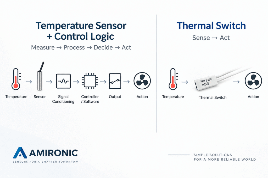
The Solution: A Temperature Switch That Makes the Decision Itself

When there is no need to know the exact temperature value, but only to take action when a certain threshold is crossed, a Temperature Switch can provide a simpler and more direct solution.

Instead of generating a signal that represents the temperature, the thermal switch changes the state of its electrical contact when it reaches a predefined temperature.

For example, in a Normally Closed – NC switch, the contact remains closed during normal operation.

When the temperature reaches the switching point, the contact opens.

This change of state can be used to stop a system, interrupt a circuit, or send a signal to the control system.

The principle is fundamentally different from that of a temperature sensor:

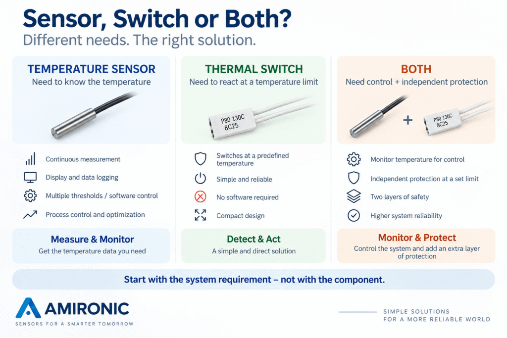
A Temperature Sensor tells the system what the temperature is.

A Temperature Switch tells the system when it is time to take action.

How Does a Bimetal Thermal Switch Work?

One of the common technologies used in Temperature Switches is based on a Bimetal element.

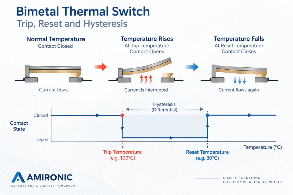
A bimetal element consists of metals with different coefficients of thermal expansion. As the temperature changes, the difference in expansion creates mechanical movement.

In a thermal switch, this movement is used to physically operate an electrical contact.

There is no need to measure the temperature, convert it into a voltage or resistance value, process it in software, and then make a decision.

The temperature itself activates the switching mechanism.

For example, if a switch with a 100°C switching point is selected, the system can be designed so that when the installation area reaches this temperature, the contact changes state.

With an Automatic Reset switch, once the system cools below the switch’s reset temperature, the contact returns to its original state.

It is important to understand that the reset temperature is not necessarily the same as the switching temperature. The difference between them is often referred to as Hysteresis or Switching Differential, and it helps prevent the switch from rapidly cycling between ON and OFF when the temperature is close to the switching point.

Why Can This Simplicity Be an Advantage?

A complete temperature measurement system includes several components and stages that must operate correctly before a decision can be made.

The sensor must measure correctly, the signal must reach the controller, the measurement system must interpret it, and the software must perform the appropriate action.

With a Temperature Switch, the decision function can be implemented locally, directly at the point where the temperature is being detected.

This can be particularly useful when a simple and independent overtemperature protection function is required, without necessarily relying on software.

But simplicity also comes with limitations.

A thermal switch does not tell the system that the temperature is 73.4°C. Nor does it allow the system to display a temperature graph, perform Data Logging, or change the switching point through software.

It provides a different type of information:

The threshold has been crossed – or it has not.

Therefore, the question is not which solution is “better.”

The question is what information the system actually needs in order to perform its function.

NC or NO – The Choice Is Not Just About Logic

Once we have determined that a Temperature Switch is suitable for the application, one of the first questions is what the contact state should be at the normal operating temperature.

The two basic options are:

Normally Closed – NC
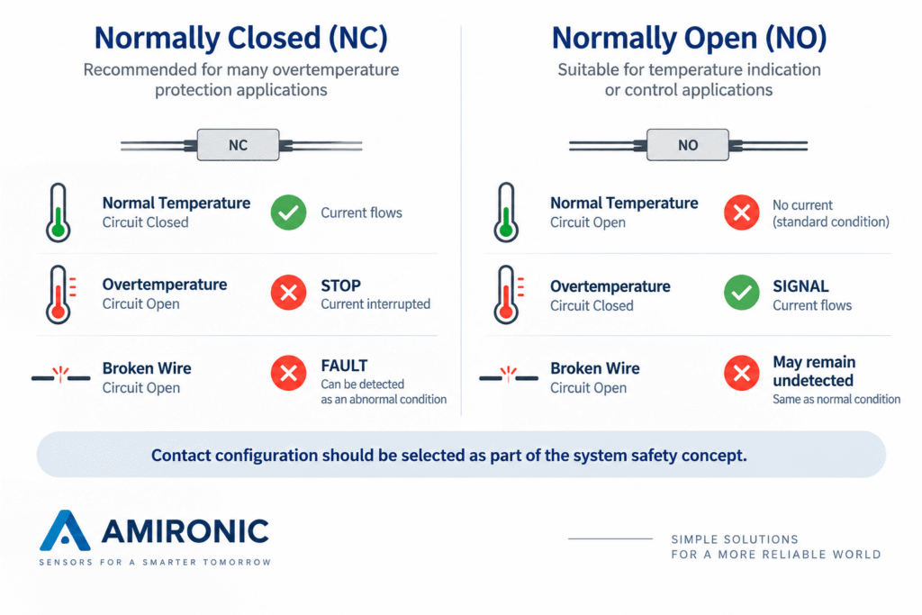
The contact is closed at normal temperatures and changes state when the switching temperature is reached.

Normally Open – NO
The contact is open at normal temperatures and closes when the switching temperature is reached.

At first glance, this may seem like a simple system logic decision.

In practice, however, the choice can also have implications for Fail-Safe design.

Why Can NC Be an Advantage in a Protection Circuit?

Suppose the thermal switch is part of a circuit designed to protect a motor against overheating.

In an NC architecture, electrical continuity exists during normal operation. When the temperature reaches the switching point, the contact opens, allowing the system to detect the event or stop operation.

But the circuit can also open for other reasons.

For example:

  • A broken wire
  • A disconnected connector
  • A damaged contact
  • A wiring fault

If the control system is designed appropriately, these conditions can also appear as a loss of electrical continuity and cause the system to transition to a safe state.

In contrast, in a simple NO circuit, a broken wire may appear exactly the same as the normal condition in which the contact is still open.

Therefore, in certain protection applications, NC makes it possible to design a system in which not only an overtemperature condition, but also certain wiring faults, can be detected as an abnormal condition.

However, using an NC contact does not automatically make a system Fail-Safe.

Fail-Safe is a characteristic of the entire system – including the sensor or switch, wiring, controller, logic, and the way the system responds to a fault.

Should the Switch Disconnect the Load Directly?

This is an important point that is sometimes overlooked.

The fact that a Temperature Switch contains an electrical contact does not necessarily mean that every motor, heating element, or other load can be connected directly through it.

Every switch has defined electrical ratings, including voltage and current, and the type of load can have a significant effect on the switching requirements.

A motor, for example, may draw a high inrush current. An inductive load can also impose very different switching conditions compared with a resistive load.

Therefore, two basic architectures are possible:

Direct Switching
When the switch rating is suitable for the load and operating conditions, the contact may in some cases be used to switch the load directly.

Control Circuit Switching
The Temperature Switch changes the input state of a controller, relay, contactor, or another protection circuit, and the appropriate device performs the actual load switching.

The choice must be based on the electrical specifications of the switch and the requirements of the actual application.

A Practical Example: Limitor Temperature Detector P

A good example of this approach is the Limitor Temperature Detector P.

It is a compact Normally Closed temperature switch designed for applications requiring reliable switching at a predefined temperature.

According to the manufacturer, the P series offers switching temperatures from 40°C to 150°C, selectable in 5°C steps, with tolerance options of ±5K or ±10K, depending on the selected configuration.

Its compact design allows the switch to be installed close to the area that needs protection, including applications such as electric motors, transformers, and small electrical equipment.

This brings us back to the original point:

If we do not need to know the temperature continuously, but instead need a defined response when the temperature crosses a specified limit, a small and relatively simple component may sometimes provide exactly the function the system requires.

When Should You Choose a Temperature Switch and When Should You Choose a Temperature Sensor?

After all these considerations, the decision itself can be relatively straightforward.

If the system needs to know the actual temperature, a sensor is required.

If the system mainly needs to know that a temperature threshold has been crossed and take action, a Temperature Switch may be the more appropriate solution.

When Is a Temperature Sensor the Right Choice?

A temperature sensor is appropriate when the actual temperature value is important to the system.

For example:

  • Continuous temperature measurement is required
  • The temperature needs to be displayed to the user
  • Data Logging is required
  • Multiple alarm or action thresholds are needed
  • Switching points need to be adjustable through software
  • Continuous control, such as PID, is required
  • Temperature trends need to be monitored, rather than simply detecting a threshold crossing

In these applications, an RTD, NTC, Thermocouple, or another type of temperature sensor provides information that can be processed and used by the system in different ways.

When Is a Temperature Switch the Right Choice?

A Temperature Switch is particularly suitable when the requirement is simple and clearly defined:

When a specific temperature is reached – change state.

For example:

  • Motor overtemperature protection
  • Heating element protection
  • System shutdown in the event of overheating
  • Turning a fan on or off
  • Generating a temperature alarm
  • Local protection of a specific component or area within the system

In these cases, there may be no need to generate a continuous temperature value and send it to a control system.

Sometimes the Right Solution Is Both

A Temperature Sensor and a Temperature Switch are not necessarily competing solutions.

In some systems, it makes sense to use both.

The temperature sensor can be used by the control system for monitoring, optimization, data logging, and normal operational control.

At the same time, a separate Temperature Switch can provide an additional layer of overtemperature protection.

For example, a system may continuously measure motor temperature and manage its operation through software.

However, if for some reason the control system does not respond as intended and the temperature continues to rise, a thermal switch installed on the motor can provide an additional protection path that does not rely on the same measurement and software chain.

In this case, the system effectively has two separate functions:

Temperature Sensor → Controller → Software → Normal Temperature Management

And separately:

Temperature Switch → Overtemperature Protection

This can be a particularly useful architecture when the goal is to separate Control from Protection.

However, simply adding two components does not automatically make a system safe or redundant. The complete system architecture and possible failure modes must still be evaluated.

What Should Be Defined Before Selecting a Temperature Switch?

Even a relatively simple component requires careful selection.

Before choosing a switch, at least the following parameters should be defined:

Trip Temperature
At what temperature should the contact change state?

Tolerance
What deviation from the nominal switching point is acceptable?

Reset Temperature / Differential
At what temperature should the contact return to its original state?

NC or NO
What should the contact state be during normal operation, and what should happen during an overtemperature condition?

Automatic Reset or Latching Solution
Should the system be allowed to resume operation after cooling, or should intervention be required before restarting?

Electrical Rating
What voltage and current must the contact switch, and what type of load is involved?

Operating Temperature Range
Under what environmental conditions must the switch itself operate?

Mechanical Integration
Where and how will the switch be installed?

And this last point is particularly important.

A 100°C Temperature Switch Does Not Necessarily Protect a System at 100°C

The switching point of the component is only part of the story.

The switch responds to the temperature that actually reaches it, which is not necessarily the temperature at the hottest point in the system.

If the switch is installed too far from the heat source, if there is significant thermal resistance between the critical area and the switch, if airflow cools the switch, or if the thermal response of the installation is too slow, the component being protected may already be at a significantly higher temperature by the time the switch itself reaches its switching point.

This is exactly the same system-level mistake that can also occur with a temperature sensor:

The right component installed in the wrong location can still result in the wrong solution.

Therefore, the Trip Temperature should not be selected based solely on the maximum allowable temperature of the system.

The installation location, heat transfer, rate of temperature rise, thermal response time, and the possible temperature difference between the critical area and the temperature actually seen by the switch must also be taken into account.

Case Study – Protecting an Electric Motor Against Overheating

Let us consider a simple example.

A system includes a small electric motor that operates for extended periods. Under normal operating conditions, the temperature remains within the allowable range. However, high mechanical loads, a stalled rotor, a cooling system failure, or unusual environmental conditions can cause the windings to overheat.

The engineering objective is clear:

Prevent the motor from continuing to operate when the winding temperature reaches a level defined as unsafe.

Option 1 – Measure the Temperature

A Temperature Sensor can be installed near the motor windings.

The sensor sends information to the control system, which measures the temperature and compares it with a threshold defined in software.

When the threshold is exceeded, the controller commands the motor to stop.

This architecture is particularly suitable when the system already needs to know the motor temperature for monitoring, control, data logging, or maintenance purposes.

But suppose our system does not need to know whether the winding temperature is 65°C, 78°C, or 91°C.

We need only one function:

When a predefined temperature is reached – stop the motor.

Option 2 – Protect the Motor Using a Temperature Switch

In this case, a Temperature Switch can be installed as close as possible to the area that needs to be protected.

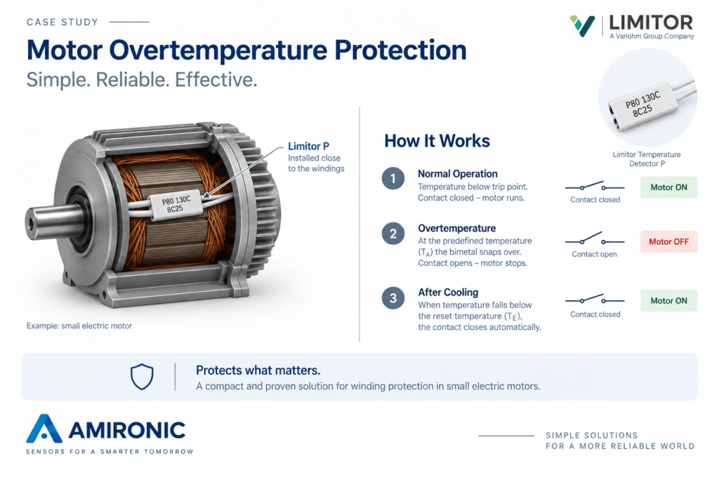
For example, the Limitor Temperature Detector P uses a bimetal disc designed for a defined Cut-off Temperature.

When the disc reaches the switching temperature TA, it snaps to its reverse position, opening the contact and interrupting electrical continuity in the circuit.

After the temperature falls to the Closing Temperature TE, the disc returns to its original position and the contact closes automatically.

In other words, the protection function does not require continuous temperature measurement in order to make the switching decision.

Why Install It Inside the Motor?

This highlights one of the most important principles of Temperature Protection:

Selecting the correct switching temperature is not enough. The temperature must also be detected at the correct location.

If the switch is installed on the motor housing, the temperature it experiences may be different from the actual winding temperature.

The windings can heat up rapidly, while the thermal mass of the motor and the thermal path between the windings and the housing can cause the housing temperature to respond more slowly.

Therefore, when the objective is to protect the windings, there is an advantage to positioning the protection device as close as practical to the relevant heat source, depending on the motor construction and thermal design.

Physical size therefore becomes an important engineering parameter, not merely a mechanical consideration. Limitor describes the P as one of its most compact thermostats, with a construction that provides good thermal conduction and fast response.

Suppose We Select a 120°C Cut-off Temperature

The P series offers selectable Switching Temperatures from 40°C to 150°C, in 5°C increments. Tolerance options of ±5K and ±10K are available.

For this example only, suppose that after performing a thermal analysis of the motor, 120°C is determined to be the appropriate switching point for the application.

During normal operation:

Motor operating → P contact closed → Motor allowed to operate

When the temperature around the switch reaches the switching point:

Overtemperature → P contact opens → Protection circuit reacts → Motor stops

After cooling:

Temperature falls → Reset temperature reached → P contact closes again

But there is an important distinction here.

The fact that the switch closes again does not necessarily mean that the motor should automatically restart.

How the system returns to operation is a system-level design decision.

In one application, Automatic Restart may be acceptable. In another, the control system may require a Reset, operator intervention, or investigation of the cause of the overheating before allowing the motor to operate again.

What If the Motor Current Exceeds the Switching Capacity of the P?

Here again, it is important to distinguish between detecting an Overtemperature condition and switching the motor power.

According to the P datasheet, the specified switching rating includes 250V and 2.5A under the conditions defined by the manufacturer. The exact rating must always be evaluated against the load type and the actual application.

If the motor or switching conditions are not compatible with the contact rating, this does not mean that a Temperature Switch cannot be used.

Instead of using the P to interrupt the motor current directly, it can be incorporated into a Protection / Control Circuit, with an appropriately rated device performing the actual power switching.

In this way, a small component installed close to the critical thermal area can provide the system with one very simple piece of information:

The temperature is still within the allowable range – or it is time to stop.

What Is the Right Solution for Your System?

The choice between a Temperature Sensor and a Temperature Switch should begin with the system requirement, not with the type of component.

The first question should not be “Which temperature sensor should we choose?” but rather:

What does the system need to do with the temperature information?

If the system needs to know the actual temperature, monitor it, record it, or use it for control, a Temperature Sensor is required.

If the primary requirement is to take action when a defined temperature threshold is crossed, a Temperature Switch may provide a simpler and more direct solution.

And in systems that require both monitoring and control as well as an additional layer of protection, the right solution may be to use both.

Quick Checklist for Selecting the Right Solution

Before selecting a component, consider the following questions:

  • Is continuous temperature measurement required, or only detection of a threshold crossing?
  • What Trip Temperature is required?
  • What Tolerance is acceptable at the switching point?
  • What should the Reset Temperature be?
  • Is Normally Closed – NC or Normally Open – NO required?
  • Is Automatic Reset appropriate for the application, or should the system logic prevent automatic restart?
  • Should the switch carry the load directly, or only provide a signal to a Control / Protection Circuit?
  • What voltage, current, and type of load must be switched?
  • Where is the actual Hot Spot that needs to be protected?
  • Can the component be installed close enough to that point?
  • What thermal response time is required?
  • Is Monitoring / Data Logging / Software Control also required?
  • Is there a reason to use a Sensor + Thermal Switch as two separate functions?

For example, the Limitor Temperature Detector P offers selectable switching temperatures from 40°C to 150°C in 5°C increments, with tolerance options of ±5K or ±10K.

Summary

Not every system that requires protection against high temperatures necessarily needs a temperature measurement system.

Sometimes we need to know:

“What is the temperature right now?”

And sometimes the only question that matters is:

“Have we reached the temperature at which action needs to be taken?”

These are two different requirements – and they may require different solutions.

A Temperature Sensor provides information that can be measured, processed, displayed, and recorded.

A Temperature Switch changes state at a predefined temperature.

And in some systems, combining the two makes it possible to separate Control from Protection.

The Limitor Temperature Detector P is an example of the second approach. It operates using a bimetal disc and does not require an external power supply for temperature detection. When the Cut-off Temperature is reached, the contact opens. After cooling to the Closing Temperature, the contact automatically returns to its original state.

Typical applications include protection of primary windings in transformers, winding protection in small electric motors, and general overtemperature protection of small electrical equipment.

Ultimately, selecting the right solution does not begin with the question “Which component should we choose?”, but rather:

What do we actually need the system to know – and what do we need it to do?

Frequently Asked Questions – FAQ

What Is the Difference Between a Temperature Sensor and a Temperature Switch?

A Temperature Sensor provides information representing the temperature, allowing the system to measure and process it.

A Temperature Switch changes the state of its contact when a predefined switching temperature is reached.

In simple terms:

A Sensor measures. A Switch acts at a defined threshold.

Does a Temperature Switch Need Power to Detect Temperature?

Not necessarily.

In the Limitor Temperature Detector P, for example, temperature detection is based on a bimetal disc and does not depend on an external power supply.

What Happens When the Temperature Detector P Reaches Its Switching Temperature?

When the selected Cut-off Temperature is reached, the bimetal disc changes state and opens the contacts.

Once the temperature falls to the Closing Temperature, the disc returns to its original position and the contact closes again.

Is the Reset Temperature the Same as the Trip Temperature?

Not necessarily.

The P has a Switching Differential between the Cut-off Temperature and the Closing Temperature. According to the manufacturer, this differential depends on the Cut-off Temperature and can range from 10K to 60K.

Can the Switching Temperature Be Selected?

Yes.

The P series offers selectable Switching Temperatures from 40°C to 150°C, in 5°C increments.

What Is the Switching Temperature Tolerance?

The P series is available with a standard tolerance of ±5K, as well as a ±10K option.

Therefore, for example, a switch specified at 100°C should not be treated as a precision measuring device that switches at exactly 100.0°C.

Can a Temperature Switch Be Connected Directly to a Motor?

It depends on the electrical rating of the switch and the characteristics of the load.

The P has defined electrical Breaking Capacity ratings in its datasheet, so the actual application must be evaluated according to voltage, current, and load type.

When the switch is not suitable for directly switching the load, it can instead be used as part of a control or protection circuit.

Where Should a Temperature Switch Be Installed?

As close as practical to the thermal point that needs to be protected, depending on the system design and application requirements.

Selecting the correct switching temperature is not enough if the switch itself does not detect the relevant temperature quickly enough.

This is one reason why, in applications such as motor winding protection, the size, location, and thermal response of the component can be just as important as the temperature value printed next to °C.

Can a Temperature Switch Always Replace a Temperature Sensor?

No.

If the system needs to know the actual temperature, perform Data Logging, display the temperature, identify trends, or provide continuous control, a Temperature Sensor is the more appropriate solution.

A Temperature Switch is better suited when the primary requirement is to take action at a defined temperature threshold.

Can a Temperature Sensor and a Temperature Switch Be Used Together?

Yes.

The Sensor can be used for monitoring and normal control, while a separate Temperature Switch provides the Overtemperature Protection function.

In this type of architecture, it is important to ensure that the separation actually provides the required level of protection rather than assuming that simply having two components automatically creates redundancy.

What Applications Are Suitable for the Limitor Temperature Detector P?

Limitor lists applications for the P including protection of primary windings in transformers, winding protection in small electric motors, and general temperature protection of small electrical equipment.

Its compact construction, good thermal conduction, and fast response are among the key characteristics highlighted by the manufacturer.

🧩 Further Reading – Measurement as a System

This article is part of an engineering series exploring how reliable measurement depends on proper system design rather than on a single sensor component.

Before diving deeper into industrial sensing, you may also find the following articles in the series useful:

  • VARIOHM Group – When Measurement Is a System, Not a Component
  • How to Select Sensors for Harsh Environments: An Engineering Guide for Reliable Measurement in the Real World
  • VARIOHM Position Sensors – Engineering Position as a System, Not Just a Signal
  • Industrial Pressure Sensors – When Pressure Measurement Becomes a System Engineering Challenge
  • Industrial Temperature Sensors – When Temperature Measurement Becomes a System Engineering Challenge
  • Choosing the Right Linear Position Sensor: Why Stroke Length Is Only the Beginning
  • Contactless Rotary Position Sensors – Why More and More Systems Are Moving to Non-Contact Sensing
  • Choosing the Right Temperature Probe Mounting
  • How Differential Pressure (ΔP) Can Reveal Problems Long Before a System Shuts Down
  • Your Temperature Sensor Says 80°C. The Real Hot Spot Could Already Be at 130°C
  • Measuring Pressure Without Temperature Is Only Half the Picture
  • Does Your Thermal Protector Really Solve the Problem? Or Just Give the System Another Chance to Fail?
  • Why a Linear Position Sensor Shouldn’t Be Selected by Stroke Alone
  • Your System Has Powered Up – But Does It Know Where It Is? Absolute Position Sensors vs. Homing
  • Your Pressure Sensor May Be Accurate. Your Measurement May Not Be – Why a ±0.5% Accuracy Specification Doesn’t Guarantee a ±0.5% Measurement
  • Why Programming a Rotary Position Sensor to 360° Is Sometimes the First Design Mistake
  • Why a Dual-Channel Rotary Position Sensor Is Not Just a Backup Sensor
  • Your PT100 Sensor Isn’t Reading the Wrong Temperature – Your Wiring Might Be
  • Why Every Battery Pack Needs a Temperature Sensor – Not Just Electric Vehicles
  • Why a Standard Pressure Sensor Isn’t Always Suitable for Hydrogen Systems
  • How Do You Know If a Liquid Cooling System Is Really Working? Pressure and Temperature Tell the Story

Key Terms

Temperature Sensor
A component that provides a signal representing temperature, allowing the system to measure, monitor, record, or use the temperature value for control purposes.

Temperature Switch
A component that changes the state of an electrical contact when the temperature reaches a defined switching point. Unlike a sensor, its primary purpose is not to provide a continuous temperature value, but to detect when a threshold has been crossed.

Bimetal
An element made from two metals with different thermal expansion characteristics. A change in temperature creates mechanical movement that can be used to operate an electrical contact. The Limitor P uses a bimetal disc to perform the switching action.

Trip Temperature / Cut-off Temperature
The temperature at which the switch changes the state of its contact. In the Limitor datasheet, this is designated as TA.

Reset / Closing Temperature
The temperature to which the switch must cool before the contact returns to its original state. In the Limitor P, this is designated as TE.

Switching Differential
The difference between the Cut-off Temperature and the Closing Temperature. In the Limitor P, it depends on the Cut-off Temperature and is specified within a range of 10K to 60K.

Hysteresis
The principle whereby the reset point is different from the switching point. This difference helps prevent rapid cycling between the two contact states when the temperature is close to the switching point.

Normally Closed – NC
A contact that is closed under normal operating conditions and opens when the switching condition is reached.

Normally Open – NO
A contact that is open under normal operating conditions and closes when the switching condition is reached.

Automatic Reset
A function in which the switch automatically returns to its original state after the temperature falls sufficiently. In the Limitor P, the bimetal disc returns to its original position and the contact closes again once the Closing Temperature is reached.

Overtemperature Protection
A protection function designed to trigger a defined action when the temperature in the protected area exceeds a specified limit.

Fail-Safe
A design principle in which certain faults cause the system to transition to a safe state, or at least allow the fault to be detected as an abnormal condition. The choice between NC and NO can be part of a Fail-Safe design, but does not by itself make the entire system Fail-Safe.

Breaking Capacity
The electrical capability of a contact to interrupt a load under specified conditions. Voltage, current, and load type ratings must be evaluated before using a switch for direct load interruption.

Hot Spot
The area within a system where the critical temperature to be protected against occurs. The Hot Spot temperature can be significantly higher than the temperature at a more remote installation point.

Thermal Response Time
The time required for a temperature change in the protected area to reach the protection device and cause it to respond. Limitor highlights the compact construction and good thermal conduction of the P as characteristics that contribute to fast response.

Tolerance
The allowable deviation of the switching temperature from its nominal value. The Limitor P is available with a standard tolerance of ±5K or an optional tolerance of ±10K.

Control vs. Protection
Control manages system operation under normal operating conditions. Protection is intended to respond when an abnormal condition occurs. In some systems, a Temperature Sensor can be used for control while a separate Temperature Switch provides the protection function.

Tags: Variohm

Related Articles

Measuring Pressure Without Temperature Is Only Half the Picture

30/06/2026amironicLTD

Your PT100 Sensor Isn’t Reading the Wrong Temperature – Your Wiring Might Be

05/08/2026amironicLTD

Why Position Feedback Matters More Than Ever in Counter-UAS Swarm Defense

02/08/2026amironicLTD

Recent Posts

  • You Don’t Always Need to Measure Temperature – Sometimes You Just Need to Know When to Stop
  • MIL-STD-810 – Vibration, Shock and Environmental Conditions in Military Power Supplies
  • MIL-STD-461 for Military Power Supplies – EMI, EMC and CS101
  • MIL-STD-704 – Power Supplies for Military and Aerospace Systems
  • MIL-STD-1275 – Power Supplies and DC-DC Converters for Military Vehicles

Categories

  • Air Switch
  • Circuit Breakers
  • Elapsed Time Indicator
  • Feedthrough
  • Footswitches
  • Gears & Transmission
  • Hour Meters
  • Infra Red Switches
  • INFRARED LAMPS
  • Low Noise Inertial MEMS
  • Mechanics
  • MEMS Gyroscope
  • MEMS Inertial
  • Microelectronics
  • Motors
  • Position Sensors
  • Power Supply
  • Pressure Sensors
  • Pressure Switch
  • Temperature Sensors
  • Tungsten and Molybdenum
  • Uncategorized
  • Vacuum Switches

Quick Contact

Fill out the form and our representatives will return to you

    Name (required)

    Email (required)

    Phone

    Message

    This site is protected by reCAPTCHA and the Google
    Privacy Policy and
    Terms of Service apply.

    Amironic Ltd.

    3 Rabinovich Street, Petah Tikva 4928144 , Israel. Tel: +972-3-9047744 E-mail: office@amironic.co.il
    Email
    Facebook
    Twitter
    LinkedIn
    YouTube
    Press on the ISO Certificate below for download
    ISO 9001:2015 Certification
    • MEMS Inertial
    • Circuit Breakers
    • Footswitches
    • Mechanical & Transmisions
    • Sensors
    • Motors
    • Electronics
    • Hand Control
    • Power Solutions

    News

    • You Don’t Always Need to Measure Temperature – Sometimes You Just Need to Know When to Stop
    • MIL-STD-810 – Vibration, Shock and Environmental Conditions in Military Power Supplies
    • MIL-STD-461 for Military Power Supplies – EMI, EMC and CS101
    • MIL-STD-704 – Power Supplies for Military and Aerospace Systems
    • MIL-STD-1275 – Power Supplies and DC-DC Converters for Military Vehicles
    About AmironicContactעברית
    © 2022 Amironic All rights reserved. All Trademarks are the property of their respective owners.
    • Increase Font
    • Decrease Font
    • Black & White
    • Inverse Colors
    • Highlight Links
    • Regular Font
    • Reset