flagעברית
flagEnglish
3 Rabinovich St., Petah-Tikva, Israel
+972 3 9047744
office@amironic.co.il
Facebook
Twitter
LinkedIn
YouTube
  • Products
    • MEMS Inertial
      • Gyros & Accels
      • IMU
      • Inertial Navigation
      • AHRS
    • Circuit Breakers
      • Airpax Circuit Breakers
      • Electronic Circuit Breakers
      • Aircraft Circuit Breakers
      • Thermal Circuit Breakers
      • Sealing Solutions & Guards
    • Footswitches
      • Pedals & Bellows
      • USB
      • Air Switches
      • Medical
      • Modular Bases System
      • Industrial
      • Foot Potentiometers
      • Wireless
    • Mechanical & Transmisions
      • Gears
      • Sealing Solutions
      • Gearboxes
      • Couplings
      • Shafts & Bearings
      • Fasteners
      • Mechanical & Springs
      • Linear Motion
      • Anti-Vibration
    • Sensors
      • Thermostats
      • Temperature
      • Position
      • Pressure
      • Speed
      • Level Sensor
      • Load Cells
      • Flex Sensors
      • Membrane Potentiometer
    • Motors
      • Geared DC
      • Brushless DC
      • Step Motors with Gearbox
      • Torque Motors & Brushless Servo
      • DC Motors
    • Electronics
      • Xenon & IR Lamps
      • Counters & Meters
      • Microelectronics Packaging
      • Waterproof Switches
      • Micro Switches
    • Hand Control
      • Operator Controls (JOYSTICK)
      • Electrical
      • Pneumatic (Medical)
      • USB Hand Control
      • Air Push Button
      • Pressure Switch
      • IR Switch
    • Power Solutions
      • Rugged & Military Power Supply
      • Input Power Protection
      • Sealed Military Power Adaptor
      • Triple Output Military Power Supply Series – up to 250 W
    • Materials
      • Molybdenum and Advanced Alloys (TZM, MOLA, HCT)
      • Tungsten (Wolfram) and Advanced Alloys – High-Performance Materials for Extreme Conditions
      • Materials for Gears
  • Shop
  • Companies
  • About Amironic
  • News
  • Contact
Product was added to your cart

Cart

waze

When the Mission Goes High-Dynamic: What Happens to a Tactical IMU Under Extreme Motion?

MEMS Inertial15/09/2026amironicLTD

In a system that moves slowly and predictably, it is relatively easy to evaluate the performance of an IMU – Inertial Measurement Unit.

Connect the sensor, examine the bias, look at the noise level, evaluate stability over time, and the results may look excellent.

But real-world aerospace and defense systems do not always behave like a laboratory bench.

An airborne platform may change direction rapidly. A stabilized system may experience a sudden mechanical disturbance. An autonomous vehicle may transition from a smooth surface into a severe vibration environment. In demanding aerospace and defense applications, a Tactical IMU may also be exposed to high acceleration, mechanical shock, vibration and very high angular rates.

Under these conditions, the engineering question changes:

It is no longer only how accurate the IMU is when the system is stable, but what happens to the measurement when the dynamics become extreme.

This is why selecting a High-Dynamic IMU requires looking beyond familiar specifications such as Bias Stability and Angle Random Walk (ARW).

The engineer must also consider gyroscope and accelerometer measurement ranges, bandwidth, data rate, latency, shock and vibration performance, acceleration sensitivity, and the ability of the MEMS IMU to continue delivering useful inertial data while the platform itself becomes increasingly difficult to measure.

What Is a High-Dynamic IMU?

The term High-Dynamic IMU does not necessarily describe a single standardized performance category or a universally defined numerical threshold.

Instead, it generally refers to an IMU that must provide useful inertial measurements while the platform experiences rapid changes in angular rate and acceleration, often combined with significant shock and vibration.

In a high-dynamic system, several conditions may occur simultaneously:

  • Angular rate can increase rapidly.
  • Acceleration can change within a very short period.
  • The platform structure can generate vibration across a wide frequency spectrum.
  • The control system may require inertial data at a very high update rate.
  • The delay between physical motion and the arrival of usable sensor data can become significant.
  • The gyroscope or accelerometer may approach its full-scale measurement limits.

This means that an IMU that looks excellent according to one specification may be less suitable when the complete operating environment is considered.

For example, a MEMS gyroscope with very low noise provides little benefit if the actual angular rate exceeds its measurement range and the sensor saturates.

Likewise, a wide measurement range alone is not sufficient if the sensor bandwidth or latency cannot support the dynamics of the control system.

High-Dynamic performance is therefore not one number in an IMU datasheet. It is the relationship between platform motion, sensor limitations and control-system requirements.

For engineers selecting a Tactical Grade IMU for aerospace, defense, autonomous platforms or other high-performance control applications, understanding that relationship is far more useful than simply comparing the lowest Bias Stability number.

When an IMU Stops Seeing What Is Really Happening

Consider a platform performing a rapid maneuver.

As long as the angular rate remains within the full-scale range of the gyroscope, the motion can be measured.

But suppose the MEMS Gyroscope is configured for ±300°/s and the platform briefly exceeds that limit.

The sensor does not simply continue measuring with slightly reduced accuracy.

It has reached saturation.

Once this happens, the output can no longer represent the full physical motion experienced by the platform.

If the control or navigation algorithm integrates angular-rate measurements to estimate changes in orientation or attitude, even a short period of unmeasured motion can introduce an error into the attitude estimate.

This illustrates an important principle when selecting a High-Dynamic Tactical IMU:

Measurement range is not merely a sensor specification. It determines which motions the system can actually measure.

The correct question is therefore not:

“Is ±300°/s a large gyroscope range?”

The better question is:

“What is the maximum angular rate my platform can generate, including transients and abnormal but operationally relevant events?”

The same principle applies to the accelerometer.

A system that normally operates near 1g may experience much higher acceleration for short periods. If the accelerometer measurement range does not cover these events, the inertial measurement can saturate precisely when the platform reaches its most demanding dynamic condition.

±300°/s or ±2000°/s – Is a Wider IMU Range Always Better?

It is tempting to conclude that the safest solution is simply to select the widest available measurement range.

That is not necessarily the correct engineering decision.

Measurement Range should not be considered in isolation. Depending on the sensor architecture and configuration, range may be related to Noise, Resolution, Scale Factor and other performance characteristics. The objective is therefore not to select the IMU with the largest number in the datasheet, but to select a range that matches the actual Dynamic Envelope of the application.

The Gladiator Technologies LandMark IMU family provides a useful example.

The LandMark 006 IMU is a compact six-axis Tactical Grade MEMS IMU combining three MEMS gyroscopes and three accelerometers. It offers a gyroscope range of ±300°/s and an accelerometer range of ±15g. In the VELOX PLUS configuration, it supports bandwidth up to 600 Hz and data rates up to 10 kHz, together with a very low digital message delay of approximately 20 µs.

These characteristics make the Gladiator LandMark 006 particularly interesting for high-performance control, stabilization, autonomous systems and aerospace applications that require fast inertial data while remaining within this dynamic range.

The Gladiator Technologies LandMark 007 IMU, by contrast, was developed specifically for High Dynamic Applications. It extends the available dynamic envelope significantly, with gyroscope ranges up to ±2000°/s and accelerometer ranges up to ±98g. The LandMark 007 also uses Gladiator’s high-speed VELOX architecture, with VELOX PLUS configurations supporting high data rates and bandwidth up to 600 Hz.

Both are high-performance MEMS IMUs.

Both are designed for demanding applications.

But they address very different dynamic envelopes.

That is where proper Tactical IMU selection begins.

The question is not whether the LandMark 006 or LandMark 007 is the “better” IMU.

The real engineering question is:

Which Gladiator Technologies IMU is matched to the motion, acceleration, shock, vibration and control-loop requirements that the platform will actually experience?
Shock Rating Is Not Measurement Range

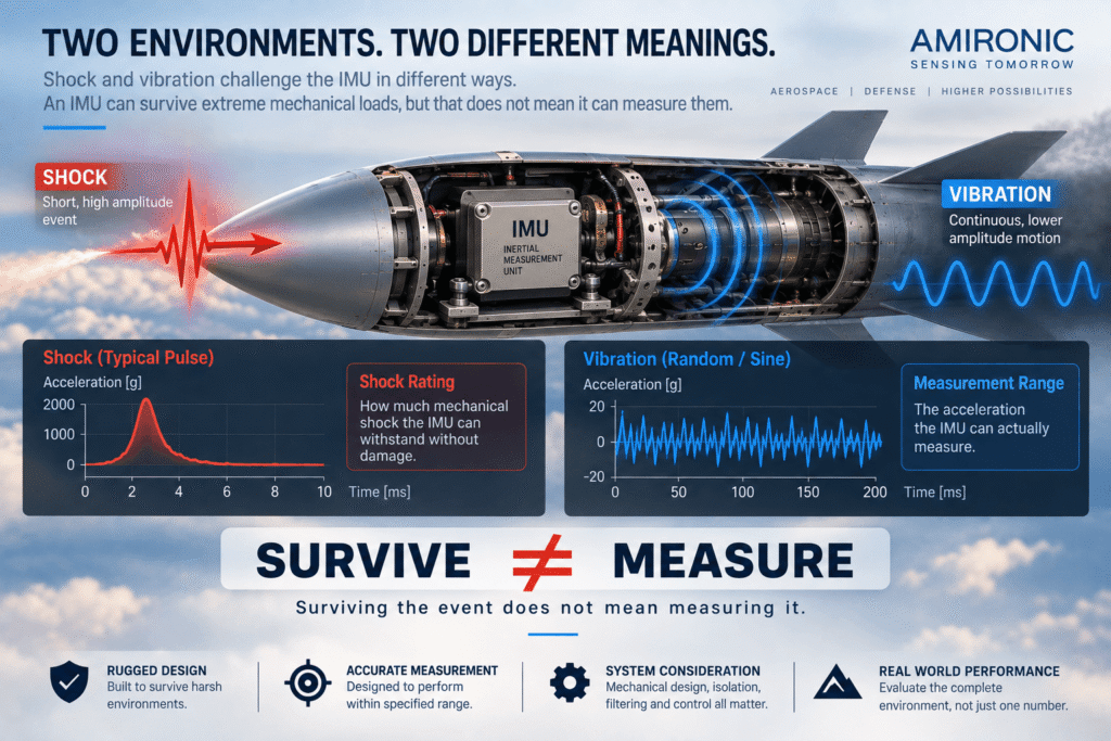
One of the easiest mistakes to make when reading an IMU datasheet is to confuse two specifications that may both be expressed in g, but describe fundamentally different capabilities:

Accelerometer Measurement Range and Shock Survivability.

For example, a Tactical IMU may specify an accelerometer measurement range of ±15g while also listing a shock rating of hundreds or even thousands of g.

That does not mean the accelerometer can measure hundreds or thousands of g.

The Accelerometer Measurement Range defines the acceleration range the sensor is designed to measure. Shock Survivability, on the other hand, generally describes the ability of the IMU to withstand a short-duration mechanical shock without permanent damage, under the test conditions specified by the manufacturer.

The distinction is fundamental:

Survival is not Measurement.

A MEMS IMU may survive a mechanical event far beyond its accelerometer measurement range while simultaneously entering saturation and providing no useful acceleration measurement during that event.

When selecting a High-Dynamic IMU for aerospace and defense applications, engineers should therefore ask two separate questions:

  1. Can the Tactical IMU survive the expected mechanical environment?
  2. Can the IMU actually measure the motion that must be captured within that environment?

In some applications, the answer to the first question may be yes while the answer to the second is no.

Vibration – When the Problem Is Continuous

Shock is typically a short-duration event.

Vibration may accompany the platform throughout a significant portion of its mission.

Motors, propellers, actuators, rotating components, airflow and structural dynamics can all generate mechanical energy across different frequencies. Because the MEMS IMU is physically mounted to the platform, it is inevitably exposed to at least part of this vibration environment.

This creates an important measurement challenge.

The Tactical IMU must measure the actual motion of the platform, but it is simultaneously exposed to both the motion the control system wants to observe and vibration that it may not want entering the control or navigation solution.

The result is not always simply “more noise.”

In a real system, vibration can interact with mechanical resonances, unwanted frequency components, sampling effects and sensor nonlinearities. Aliasing, resonance and vibration-induced measurement errors can therefore affect accelerometer and gyroscope outputs in ways that are not obvious from static laboratory specifications.

This is why two Tactical Grade IMUs with apparently similar Bias and Noise specifications may not necessarily deliver identical system-level performance when installed on a vibrating aerospace or defense platform.

Why Can’t We Simply Filter the Vibration in Software?

The intuitive response is often:

“Just add a Low-Pass Filter and remove the vibration.”

Filtering can certainly be part of the solution.

But filtering is not free.

More aggressive filtering can introduce Phase Delay and reduce the ability of a fast control system to respond to genuine platform motion.

This creates one of the central trade-offs in a High-Dynamic IMU application:

We want to reject vibration and unwanted noise without filtering out the real motion that the control system is trying to measure.

If the vibration frequencies are well separated from the useful motion bandwidth, this separation may be relatively straightforward.

When the frequency ranges begin to overlap, however, the problem becomes considerably more difficult.

At that point, engineers need to consider the complete measurement and control chain:

Mechanical Environment → Tactical IMU → Sampling → Filtering → Control Algorithm

rather than looking only at the Noise specification in an IMU datasheet.

What Is Vibration Rectification Error?

Another important phenomenon in high-performance MEMS inertial sensors is Vibration Rectification Error (VRE).

Ideally, a symmetrical vibration around zero should average out over time.

In practice, sensor nonlinearities can cause high-frequency vibration to produce an apparent DC component in the measurement. Instead of seeing only noise oscillating around the true value, the system may also observe an apparent shift in Bias.

This matters because digital filtering after the measurement may not necessarily remove an error that has already been converted into a low-frequency or DC component.

For this reason, in applications with significant vibration it is not enough to consider only the Noise Density of the MEMS accelerometer or gyroscope.

Engineers also need to understand how the Tactical IMU behaves under the actual vibration environment of the platform.

This is particularly relevant when evaluating a high-performance MEMS IMU for demanding aerospace, defense, stabilization, autonomous-system and high-dynamic control applications.

High-Dynamic Does Not Simply Mean High-G

It is easy to think of a High-Dynamic IMU as simply an IMU designed for high acceleration.

But acceleration is only one part of the problem.

A platform may experience only 2g while simultaneously undergoing extremely rapid angular motion. Another system may experience substantial linear acceleration with relatively little rotation. A third may remain comfortably within both its gyroscope and accelerometer measurement ranges while requiring an exceptionally fast control-loop response.

For this reason, it is useful to separate the different dimensions of High-Dynamic IMU performance:

Linear Acceleration – How much acceleration must the IMU measure?

Angular Rate – How fast can the platform rotate?

Angular Acceleration – How rapidly can the angular rate itself change?

Frequency Content – At what frequencies does the relevant motion occur?

Transient Duration – How long do extreme dynamic events last?

Shock and Vibration Environment – What mechanical environment actually reaches the IMU mounting location?

Control Loop Requirements – How quickly must the system receive and respond to inertial measurements?

Only when these factors are considered together can engineers begin to define the true Dynamic Envelope of the application.

And that Dynamic Envelope, rather than a single headline specification, should drive the selection of a Tactical Grade MEMS IMU – whether the requirement ultimately points toward a compact solution such as the Gladiator Technologies LandMark 006, or toward a wider-range High-Dynamic IMU such as the LandMark 007.

When Everything Happens Fast – Range Alone Is No Longer Enough

Suppose we have selected a Tactical IMU with measurement ranges that appear suitable for the application.

The gyroscope does not reach saturation. The accelerometer remains within its full-scale range. The IMU is also designed to withstand the expected shock and vibration environment.

Does that mean it is suitable for a High-Dynamic system?

Not yet.

In a rapidly maneuvering platform, it is important to understand not only what the IMU can measure, but also how quickly it can follow changes in motion and how quickly that information becomes available to the control system.

This brings three specifications into focus that are often confused when comparing MEMS IMUs:

Bandwidth, Data Rate and Latency.

Each describes a different part of the sensor’s dynamic performance.

IMU Bandwidth – How Fast Can the Sensor Actually Follow Motion?

Bandwidth describes the frequency range over which the IMU and its signal chain can respond to motion.

For a relatively slow-moving system, extremely high bandwidth may be less important.

But as platform dynamics become faster, the situation changes.

Rapid motion contains higher-frequency components. If the bandwidth of the MEMS gyroscope, accelerometer or associated filtering chain is insufficient, part of the relevant dynamics may be attenuated or phase-shifted before the information ever reaches the controller.

For a High-Dynamic Tactical IMU, the engineering question should therefore not simply be:

“What is the bandwidth of the IMU?”

A more useful question is:

“Does the bandwidth of the complete inertial measurement chain cover the motion frequencies that the control system actually needs to observe?”

This distinction becomes particularly important in fast stabilization, aerospace, defense and autonomous-control applications where sensor dynamics are directly connected to control-loop performance.

IMU Data Rate – How Often Do We Receive a New Measurement?

Data Rate describes how frequently the IMU provides new samples or measurement messages to the host system.

For example, a 10 kHz data rate means that the system can receive up to 10,000 measurement updates per second.

That is an impressive number, but it does not mean that the IMU can necessarily measure physical motion with a bandwidth of 10 kHz.

Consider a Tactical Grade IMU with a 600 Hz bandwidth and a 10 kHz data rate.

There is no contradiction.

The system can receive measurements at a very high update rate even though the useful physical signal bandwidth is lower.

High-rate sampling and output can be valuable for fast control loops, synchronization, signal processing and applications where very short intervals between successive inertial measurements are important.

The two specifications should therefore never be treated as interchangeable:

Data Rate tells us how often new data becomes available.

Bandwidth tells us how rapidly the physical motion can change while still being represented usefully by the sensor chain.

This distinction is particularly important when comparing high-speed MEMS IMUs, because a large output-rate number alone does not define dynamic performance.

IMU Latency – The Measurement Can Be Correct but Late

A third parameter can become critical in a High-Dynamic IMU application: Latency.

Suppose the IMU measures the platform motion accurately.

The problem is that the measurement reaches the controller too late.

In a slow-moving system, a small delay may have little practical significance.

But when the platform is changing state rapidly, the measurement must pass through sensing, filtering, internal processing and the digital interface. By the time the controller receives the information, the physical system may already have moved to a different state.

In other words:

The control system can receive an accurate measurement of what happened a moment ago when it needs to know what is happening now.

For a fast control loop, IMU latency is therefore not merely a communications specification. It is part of the total system timing budget.

The complete chain needs to be considered:

Sensing → Filtering → Processing → Communication → Control Algorithm → Actuation

Every stage introduces some delay.

And as platform dynamics become faster, that delay becomes increasingly important.

This is one reason why low-latency Tactical IMUs can be particularly valuable in demanding stabilization, autonomous control and aerospace applications.

Case Study – Gladiator Technologies LandMark 006 vs. LandMark 007

The difference between these requirements can be illustrated by comparing two Gladiator Technologies MEMS IMUs designed for different dynamic envelopes.

The Gladiator LandMark 006 IMU is a compact six-axis solution for applications requiring high-performance inertial measurements in a small package. It offers a gyroscope measurement range of ±300°/s and an accelerometer range of ±15g.

With VELOX PLUS, the LandMark 006 supports bandwidth up to 600 Hz and data rates up to 10 kHz, together with very low digital message delay.

This combination makes the LandMark 006 Tactical IMU particularly attractive when the system requires fast inertial data, high bandwidth and low latency while its expected motion remains within the available measurement ranges.

The Gladiator LandMark 007 IMU, on the other hand, was developed specifically for High Dynamic Applications and significantly expands the measurement envelope, with gyroscope ranges up to ±2000°/s and accelerometer ranges up to ±98g.

That does not mean the LandMark 007 is simply a “better IMU.”

It means it was designed for a different dynamic problem.

If a platform never approaches 300°/s or 15g, automatically selecting a 2000°/s and 98g configuration does not necessarily provide a system-level advantage.

But if the application includes operational scenarios in which the lower measurement ranges may be exceeded, the selection question changes completely:

What is the most extreme dynamic event that the Tactical IMU must actually measure – not merely survive?

That should be one of the first questions asked when selecting a High-Dynamic IMU for aerospace, defense or autonomous systems.

Four IMU Specifications That Must Be Read Together

Consider an IMU datasheet containing four impressive specifications:

±2000°/s Gyroscope Range
600 Hz Bandwidth
High Data Rate
Low Latency

It is easy to look at any one of these specifications and describe the sensor as “fast.”

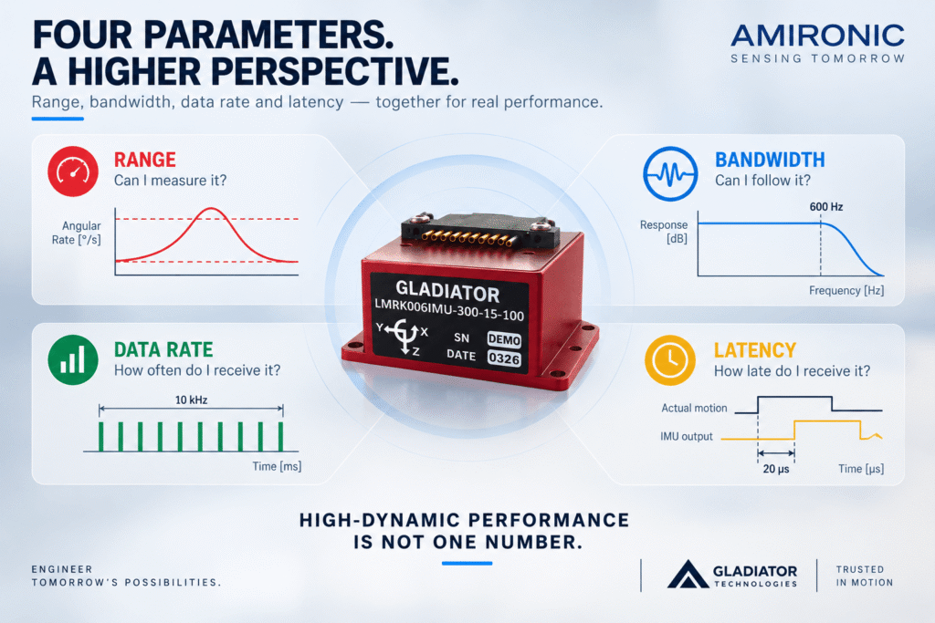
But a High-Dynamic Tactical IMU can only be evaluated properly when the relationship between these parameters is understood.

Range determines whether the IMU can measure the full magnitude of the motion.

Bandwidth determines whether the sensor chain can follow the relevant rate of change and frequency content.

Data Rate determines how frequently the host system receives a new inertial measurement.

Latency determines how much time passes between the physical event and the availability of useful measurement data.

Only when all four parameters match the application can we begin to evaluate the true Dynamic Performance of a MEMS IMU.

For this reason, selecting a Tactical Grade IMU should never be reduced to finding the highest data rate, the widest gyroscope range or the lowest latency in isolation. The objective is to match the complete sensor architecture to the Dynamic Envelope of the mission.

How to Define the Dynamic Envelope Before Selecting an IMU

One of the most common mistakes in Tactical IMU selection is starting with the products.

Engineers open several IMU datasheets, compare Bias Stability, Noise, Measurement Range and Bandwidth, and then try to determine which sensor offers the “best” specifications.

For a High-Dynamic IMU application, it is usually better to reverse that process.

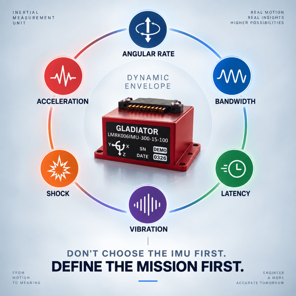
First define the motion and mechanical environment of the platform. Then select the IMU that matches it.

The objective is to establish a Dynamic Envelope that describes not only normal operating conditions, but also the most demanding events that the MEMS IMU must still measure accurately enough to remain useful to the system.

1. What Is the Maximum Angular Rate?

Start by evaluating all three axes independently.

A platform may experience a very high Roll Rate while Pitch and Yaw remain significantly lower.

It is also important not to consider only nominal motion.

The analysis should include relevant transients, extreme maneuvers, external disturbances and other events that remain within the intended operating envelope of the platform.

If the MEMS Gyroscope reaches saturation during one of these events, part of the actual motion may no longer be represented in the sensor output.

For this reason, an appropriate Engineering Margin should generally be maintained between the maximum expected angular rate and the Full-Scale Range of the gyroscope.

But this does not mean selecting an unnecessarily wide range.

The objective is not Maximum Range. The objective is Appropriate Range.

2. What Is the Maximum Acceleration That Must Actually Be Measured?

The same process should be applied to the accelerometer.

Here, it is particularly important to distinguish between acceleration that the Tactical IMU must measure and mechanical shock that it only needs to survive.

For example, a platform may operate most of the time under moderate acceleration, experience substantially higher acceleration during short dynamic events, and also be exposed to a mechanical shock with a much higher peak level.

These are three different requirements.

If all three are reduced to a single “Maximum g” value, it becomes very easy to select a MEMS IMU based on the wrong specification.

Accelerometer Range and Shock Survivability should therefore be defined separately within the Dynamic Envelope.

3. How Quickly Does the Motion Change?

Maximum Angular Rate alone does not describe the complete dynamics of a platform.

Two systems may reach exactly the same maximum angular rate, while one reaches it gradually and the other reaches it within a very short period.

From the perspective of a control system, these are very different dynamic events.

As motion contains increasingly high-frequency components, IMU Bandwidth, Filtering and Phase Response become more important.

Therefore, when platform test data or simulation data are available, engineers should examine not only time-domain peaks but also the Frequency Content of the relevant motion and vibration.

This is particularly important when selecting a High-Dynamic Tactical IMU for fast stabilization and control applications.

4. What Is the Real Vibration Environment?

Vibration should not be treated as just another environmental specification to check off on a datasheet.

The engineer needs to understand where the vibration originates, its frequency content, and what mechanical energy actually reaches the IMU mounting location.

Motors, actuators, propulsion systems, rotating components and structural modes can generate very different vibration spectra.

Mounting location also matters.

Two identical MEMS IMUs installed at different locations on the same platform may experience significantly different mechanical environments.

Laboratory testing of a Tactical Grade IMU is important, but it cannot completely replace System-Level Testing in the actual installation configuration.

For demanding aerospace, defense and autonomous applications, the IMU should ultimately be evaluated as part of the mechanical and control system in which it will operate.

5. How Much IMU Latency Can the Control System Tolerate?

In a High-Dynamic control system, latency should be treated as a budget.

The IMU is only one contributor.

The sensor measures the motion, filters and processes the signal, and transfers the data through its interface. The Flight Computer or Controller receives that information, the control algorithm calculates a response, and a command is then sent to an actuator that has its own response time.

A simplified representation is:

Total Control Loop Delay = Sensor + Processing + Communication + Algorithm + Actuation

The latency or Digital Message Delay specified for the IMU is therefore not the entire story, but it is an important part of it.

As the required control response becomes faster, every component in this timing budget becomes increasingly significant.

This is why high bandwidth, high data rate and low latency must be considered together when selecting a High-Dynamic MEMS IMU.

Case Study: Why the Gladiator LandMark 006 and LandMark 007 Are Designed for Different Dynamic Envelopes

A comparison between the Gladiator Technologies LandMark 006 and LandMark 007 demonstrates why Tactical IMU selection should begin with the application rather than the product.

The LandMark 006 IMU combines a compact six-axis MEMS architecture with fast inertial data performance. It provides a gyroscope range of ±300°/s and an accelerometer range of ±15g. With VELOX PLUS, it supports bandwidth up to 600 Hz, data rates up to 10 kHz and very low digital message delay.

For many stabilization, control, autonomous and aerospace applications, this represents a substantial Dynamic Envelope in a compact IMU.

But some platforms require considerably wider measurement ranges.

This is where a dedicated High-Dynamic IMU such as the Gladiator Technologies LandMark 007 addresses a different requirement. The LandMark 007 was designed for High Dynamic Applications and offers gyroscope ranges up to ±2000°/s and accelerometer ranges up to ±98g.

The important point is not simply the numerical difference between the two Gladiator IMUs.

There is no universally “best Tactical IMU” independent of the application.

An IMU with an exceptionally wide measurement range is not automatically the right choice for a platform that does not require that range. In exactly the same way, an IMU with excellent Bias Stability is not necessarily the right choice if its gyroscope or accelerometer saturates during a maneuver that the system is required to measure.

Rather than selecting an IMU based on a single superlative in the datasheet, engineers should match the sensor to the Dynamic Envelope of the mission.

Engineer’s Checklist: 10 Questions Before Selecting a High-Dynamic Tactical IMU

Before selecting a High-Dynamic IMU, it is worth answering at least these ten questions:

  1. What is the Maximum Angular Rate around each of the three axes?
  2. What is the Maximum Acceleration that the system must actually measure?
  3. What Transients are expected beyond nominal operating conditions?
  4. What level of Shock must the IMU survive?
  5. What is the Vibration Profile at the actual IMU mounting location?
  6. What Bandwidth is required to preserve the relevant platform dynamics?
  7. What Data Rate does the control system require?
  8. What is the maximum acceptable Latency within the Control Loop?
  9. What Engineering Margin is required relative to the sensor measurement limits?
  10. Has the IMU been evaluated in the actual system environment rather than only under laboratory conditions?

If several of these questions cannot yet be answered, it may simply be too early in the design process to select the IMU.

Don’t Select a Tactical IMU by the Most Impressive Number

In the world of MEMS inertial sensors, it is easy to focus on one specification.

Lower Bias Stability.

Higher Data Rate.

Wider Bandwidth.

Greater Measurement Range.

But a real High-Dynamic aerospace or defense system does not evaluate specifications one at a time.

It exposes the IMU to all of these requirements simultaneously.

The Tactical IMU must remain within its measurement range, follow the relevant dynamics, operate within the real mechanical environment and deliver inertial information while that information is still useful to the control system.

This is why selecting a High-Dynamic MEMS IMU is not a competition for the highest or lowest number in the datasheet.

It is about matching the sensor to the physics of the system.

For engineers evaluating Gladiator Technologies Tactical IMUs, that distinction is also the key to choosing between products such as the LandMark 006 and the LandMark 007: define the mission’s Dynamic Envelope first, then select the Gladiator IMU architecture that fits it.

Conclusion – High-Dynamic IMU Selection Starts with the System

When a system operates in a demanding dynamic environment, no single specification can determine whether an IMU is suitable for the mission.

A wide Gyroscope Range provides little benefit if the Bandwidth cannot follow the relevant motion. High Bandwidth is not enough if the data reaches the control system with excessive delay. A high Shock Rating does not mean that the accelerometer can measure acceleration at that shock level. And excellent Bias Stability measured under laboratory conditions does not tell the entire story when the Tactical IMU is installed on a platform exposed to significant vibration.

This is why the IMU selection process should begin by defining the system’s Dynamic Envelope:

What must the IMU actually measure? How rapidly can the motion change? What Shock and Vibration environment will the sensor experience? What Angular Rates and Accelerations must remain within the measurement range? And how much delay can the control system tolerate before the inertial data is no longer sufficiently timely?

Only after these requirements are understood should different MEMS IMUs be compared.

For applications with a relatively moderate dynamic envelope, a compact high-performance IMU such as the Gladiator Technologies LandMark 006 can provide an attractive combination of inertial performance, high Bandwidth, fast Data Rate and very low Latency.

When the application requires significantly higher Angular Rates or Accelerations, a High-Dynamic IMU specifically designed for a wider measurement envelope, such as the Gladiator Technologies LandMark 007, may be the more appropriate solution.

The choice between them is not about which Gladiator IMU is universally “better.”

The real question is which Tactical IMU best matches the physics of the mission.


Frequently Asked Questions – High-Dynamic and Tactical IMUs

What Is a High-Dynamic IMU?

A High-Dynamic IMU generally refers to an Inertial Measurement Unit intended for systems that experience high angular rates, high acceleration, rapid changes in motion, or demanding Shock and Vibration environments.

There is no single numerical threshold at which an IMU becomes “High-Dynamic.” Suitability depends on the Dynamic Envelope of the application and on the combination of Gyroscope Range, Accelerometer Range, Bandwidth, Data Rate, Latency, mechanical environment and other sensor characteristics.

For aerospace, defense and autonomous applications, a High-Dynamic IMU should therefore be selected according to the complete motion and control requirements of the platform rather than a single headline specification.

Is a Wider Gyroscope Range Always Better in a Tactical IMU?

No.

The Gyroscope Range should be wide enough to cover the Maximum Angular Rate expected from the platform, including relevant Transients and an appropriate Engineering Margin.

However, there is no automatic advantage in selecting the widest possible range. Depending on the sensor architecture and configuration, Measurement Range may be related to Noise, Resolution, Scale Factor and other performance characteristics.

The objective when selecting a Tactical IMU is therefore to choose an appropriate measurement range, not necessarily the largest available range.

What Happens When an IMU Gyroscope Reaches Saturation?

When the Angular Rate exceeds the Full Scale Range of the gyroscope, the sensor can no longer represent the complete rotational motion.

This condition is known as Saturation.

In a system that integrates Angular Rate to estimate Orientation or Attitude, losing part of the rotational motion can introduce an error into the resulting attitude estimate.

For this reason, the Gyroscope Range of a High-Dynamic IMU should cover not only normal platform motion but also short-duration dynamic events that the system is required to measure.

Does a 1000g Shock Rating Mean an IMU Can Measure 1000g?

No.

Shock Rating and Accelerometer Measurement Range describe two fundamentally different capabilities.

Shock Rating generally describes the ability of the IMU to withstand a specified mechanical shock event under defined test conditions.

Accelerometer Measurement Range, on the other hand, describes the acceleration range the sensor is designed to measure.

An IMU may therefore survive a shock event far beyond its measurement range while its accelerometer is saturated during that event.

Survive ≠ Measure.

This distinction is particularly important when selecting a Tactical Grade IMU for harsh aerospace and defense environments.

What Is the Difference Between IMU Bandwidth and Data Rate?

Bandwidth describes the frequency range over which the IMU measurement chain can respond usefully to physical motion.

Data Rate describes how frequently a new measurement is made available or transmitted by the IMU.

A MEMS IMU can therefore provide a Data Rate of several kHz while its measurement Bandwidth is considerably lower.

Both specifications are important in fast control applications, but they describe different characteristics of the inertial measurement chain.

Why Is Low Latency Important in a High-Dynamic IMU?

Latency is the delay between a physical event and the availability of the corresponding measurement to the system using that information.

When a platform is changing state rapidly, even a relatively small delay can become significant for a fast Control Loop.

Engineers should therefore consider not only IMU latency, but the delay budget of the complete chain:

Sensing → Filtering → Processing → Communication → Control Algorithm → Actuation

For demanding stabilization and control applications, Low-Latency IMU performance can be just as important as high Bandwidth or a high Data Rate.

Can IMU Vibration Problems Be Solved with a Filter?

Filtering can be part of the solution, but simply applying an aggressive Low-Pass Filter is not always sufficient.

Filtering can introduce Phase Delay and can also attenuate real motion that the control system needs to observe.

In addition, nonlinear effects such as Vibration Rectification Error (VRE) can convert vibration into an apparent low-frequency Bias or Offset. Once this has occurred, conventional digital filtering after the measurement may not necessarily remove the resulting error.

Vibration should therefore be considered as part of the complete mechanical, inertial and control-system design.

What Is the Difference Between the Gladiator LandMark 006 and LandMark 007 IMUs?

Both the LandMark 006 and LandMark 007 are six-axis MEMS IMUs from Gladiator Technologies, but they address different Dynamic Envelopes.

The Gladiator LandMark 006 IMU provides a Gyroscope Range of ±300°/s and an Accelerometer Range of ±15g. With VELOX PLUS, it can support Bandwidth up to 600 Hz and Data Rates up to 10 kHz, making it particularly interesting for applications requiring fast inertial measurements in a compact package.

The Gladiator LandMark 007 IMU was designed specifically for High Dynamic Applications and offers significantly wider measurement-range options, with Gyroscope Range up to ±2000°/s and Accelerometer Range up to ±98g.

The correct choice is therefore not determined by which IMU has the larger numbers.

LandMark 006 vs. LandMark 007 is ultimately a question of matching the Gladiator IMU to the Dynamic Envelope of the application.


Important IMU Terms and Definitions

IMU – Inertial Measurement Unit
An inertial sensing unit typically combining multiple Gyroscopes and Accelerometers to measure rotational and linear motion along multiple axes.

Tactical IMU / Tactical Grade IMU
A term commonly used for an IMU providing inertial performance suitable for demanding navigation, stabilization, control and other high-performance applications. The exact performance requirements depend on the application, so the term should not be interpreted as a single universal specification threshold.

MEMS IMU
An Inertial Measurement Unit based on Micro-Electro-Mechanical Systems (MEMS) inertial sensor technology, typically integrating MEMS Gyroscopes and Accelerometers with signal processing, calibration and digital interfaces.

Gyroscope
An inertial sensor that measures Angular Rate, or rotational velocity around an axis.

Accelerometer
An inertial sensor that measures Specific Force, from which information related to acceleration and orientation relative to gravity may be derived depending on the application and processing.

Measurement Range / Full Scale Range
The maximum measurement interval for which the sensor is designed, such as ±300°/s for a Gyroscope or ±15g for an Accelerometer.

Saturation
A condition in which the input exceeds the sensor’s Full Scale Range and the output can no longer represent the complete physical motion.

Bandwidth
The frequency range over which the sensor and measurement chain can respond usefully to the measured signal.

Data Rate
The rate at which measurement data is made available or transmitted, typically expressed in Hz or kHz.

Latency
The delay between the physical event being measured and the availability of the resulting measurement for use by the system.

Shock
A short-duration mechanical event typically characterized by relatively high acceleration.

Vibration
Periodic, broadband or random mechanical motion that may occur at different frequencies and amplitudes over time.

Vibration Rectification Error – VRE
A phenomenon in which vibration interacting with sensor nonlinearities produces an apparent measurement error that can appear as a Bias or Offset.

Dynamic Envelope
The combined motion and environmental conditions within which the system must operate, including Angular Rate, Acceleration, Frequency Content, Shock, Vibration and timing requirements.

Engineering Margin
A design allowance maintained between the maximum expected requirement and the selected measurement or performance limit of the system.

🧩 Further Reading and Deeper Insight

This article is part of a broader series exploring the engineering principles behind modern inertial sensing and motion stability in advanced control and navigation systems. For deeper technical context and system-level insights, you may also find the following articles valuable:

  • Bridging Control and Navigation: How Advanced MEMS IMUs Are Redefining System Performance
  • Gyro and IMU for Advanced Control Systems
  • The Silent Problem of Precision Systems – Why Gyros and IMUs Are Control Components, Not Just Sensors
  • Why External Sync is Critical in Gyro and IMU Systems
  • Stabilization, Tracking & Time Sync: The Foundation of Precise Line-of-Sight Control
  • Mission-Grade Stabilization in Dynamic EO/IR Systems: Why Bandwidth, Data Rate, and Phase Lag Define Gimbal Performance
  • Why Gladiator? What Truly Differentiates a High-End MEMS IMU Manufacturer
  • Common Misconceptions About MEMS Inertial Sensors
  • Bias Stability vs. Bias Instability: What really determines the performance of Gyro and IMU systems in stabilization, tracking, and navigation
  • Scale Factor in MEMS IMUs – The Error That Quietly Destroys Accuracy
  • The IMU Was Excellent. The Image Still Shook.
  • 2000Hz IMU? Before You Get Impressed, Understand Three Completely Different Numbers
  • SX3: Pushing MEMS Beyond Traditional Stabilization
  • Why a Smaller IMU Can Save Months of Development
  • Your Image Still Shakes Despite Choosing a Gyroscope with Excellent Bias Stability
  • Why Replacing an IMU Can Lead to Weeks of Recalibration
  • From IMU to INS: How a Tactical Navigation System Is Really Built
  • When GPS Is Lost, It’s Already Too Late to Choose an IMU
  • Why Do Counter-UAS Systems Lose Track of a Drone Right After Detecting It?
  • When GPS Lies: Why IMUs Are Becoming Mission-Critical in the Era of Autonomous Wingmen
  • How Does a MEMS Sensor Become a Tactical-Grade IMU?
  • The Antenna Hasn’t Moved – So Why Did We Lose the Link? The Role of the IMU in Antenna Positioning Systems
  • Tactical Grade IMU: What Happens When the Mission Stops Behaving Like the Lab?
  • How to Choose an IMU for a Dynamic System – Why “More Accurate” Doesn’t Always Mean “Better”
Tags: Gladiator_Technologies

Related Articles

When GPS Is Lost, It’s Already Too Late to Choose an IMU

21/07/2026amironicLTD

From IMU to INS: How a Tactical Navigation System Is Really Built

16/07/2026amironicLTD

Why Replacing an IMU Can Lead to Weeks of Recalibration

12/07/2026amironicLTD

Recent Posts

  • When the Mission Goes High-Dynamic: What Happens to a Tactical IMU Under Extreme Motion?
  • Hands on the Patient, Foot on the System – Why Footswitches Are Still Essential in Medical Imaging
  • As AI Racks Demand More Power – What Happens to Circuit Breaker Protection?
  • Military Temperature Sensors – How to Choose the Right Temperature Sensor for Harsh Environments?
  • How to Identify an Existing Gear Without a Drawing – A Practical Measurement Guide for Engineers

Categories

  • Air Switch
  • Circuit Breakers
  • Elapsed Time Indicator
  • Feedthrough
  • Footswitches
  • Gears & Transmission
  • Hour Meters
  • Infra Red Switches
  • INFRARED LAMPS
  • Low Noise Inertial MEMS
  • Mechanics
  • MEMS Gyroscope
  • MEMS Inertial
  • Microelectronics
  • Motors
  • Position Sensors
  • Power Supply
  • Pressure Sensors
  • Pressure Switch
  • Temperature Sensors
  • Tungsten and Molybdenum
  • Uncategorized
  • Vacuum Switches

Quick Contact

Fill out the form and our representatives will return to you

    Name (required)

    Email (required)

    Phone

    Message

    This site is protected by reCAPTCHA and the Google
    Privacy Policy and
    Terms of Service apply.

    Amironic Ltd.

    3 Rabinovich Street, Petah Tikva 4928144 , Israel. Tel: +972-3-9047744 E-mail: office@amironic.co.il
    Email
    Facebook
    Twitter
    LinkedIn
    YouTube
    Press on the ISO Certificate below for download
    ISO 9001:2015 Certification
    • MEMS Inertial
    • Circuit Breakers
    • Footswitches
    • Mechanical & Transmisions
    • Sensors
    • Motors
    • Electronics
    • Hand Control
    • Power Solutions

    News

    • When the Mission Goes High-Dynamic: What Happens to a Tactical IMU Under Extreme Motion?
    • Hands on the Patient, Foot on the System – Why Footswitches Are Still Essential in Medical Imaging
    • As AI Racks Demand More Power – What Happens to Circuit Breaker Protection?
    • Military Temperature Sensors – How to Choose the Right Temperature Sensor for Harsh Environments?
    • How to Identify an Existing Gear Without a Drawing – A Practical Measurement Guide for Engineers
    About AmironicContactעברית
    © 2022 Amironic All rights reserved. All Trademarks are the property of their respective owners.
    • Increase Font
    • Decrease Font
    • Black & White
    • Inverse Colors
    • Highlight Links
    • Regular Font
    • Reset