flagעברית
flagEnglish
3 Rabinovich St., Petah-Tikva, Israel
+972 3 9047744
office@amironic.co.il
Facebook
Twitter
LinkedIn
YouTube
  • Products
    • MEMS Inertial
      • Gyros & Accels
      • IMU
      • Inertial Navigation
      • AHRS
    • Circuit Breakers
      • Airpax Circuit Breakers
      • Electronic Circuit Breakers
      • Aircraft Circuit Breakers
      • Thermal Circuit Breakers
      • Sealing Solutions & Guards
    • Footswitches
      • Pedals & Bellows
      • USB
      • Air Switches
      • Medical
      • Modular Bases System
      • Industrial
      • Foot Potentiometers
      • Wireless
    • Mechanical & Transmisions
      • Gears
      • Sealing Solutions
      • Gearboxes
      • Couplings
      • Shafts & Bearings
      • Fasteners
      • Mechanical & Springs
      • Linear Motion
      • Anti-Vibration
    • Sensors
      • Thermostats
      • Temperature
      • Position
      • Pressure
      • Speed
      • Level Sensor
      • Load Cells
      • Flex Sensors
      • Membrane Potentiometer
    • Motors
      • Geared DC
      • Brushless DC
      • Step Motors with Gearbox
      • Torque Motors & Brushless Servo
      • DC Motors
    • Electronics
      • Xenon & IR Lamps
      • Counters & Meters
      • Microelectronics Packaging
      • Waterproof Switches
      • Micro Switches
    • Hand Control
      • Operator Controls (JOYSTICK)
      • Electrical
      • Pneumatic (Medical)
      • USB Hand Control
      • Air Push Button
      • Pressure Switch
      • IR Switch
    • Power Solutions
      • Rugged & Military Power Supply
      • Input Power Protection
      • Sealed Military Power Adaptor
      • Triple Output Military Power Supply Series – up to 250 W
    • Materials
      • Molybdenum and Advanced Alloys (TZM, MOLA, HCT)
      • Tungsten (Wolfram) and Advanced Alloys – High-Performance Materials for Extreme Conditions
      • Materials for Gears
  • Shop
  • Companies
  • About Amironic
  • News
  • Contact
Product was added to your cart

Cart

waze

How to Choose an IMU for a Dynamic System – Why “More Accurate” Doesn’t Always Mean “Better”

MEMS Gyroscope, MEMS Inertial08/09/2026amironicLTD

Bias, Noise, Bandwidth, Latency and Dynamic Range – How to Balance Them When Selecting a MEMS IMU for Control, Stabilization and Navigation Systems

When engineers compare a MEMS IMU, MEMS Gyroscope, or Tactical Grade IMU, it is easy to start with the headline numbers on the datasheet.

Which IMU offers lower Bias Instability?
Which one has better Angular Random Walk?
Which Gyroscope has lower Noise?

These are important questions, but in a dynamic system, they are not enough.

Two MEMS IMUs may look very similar, and one may even appear more accurate on paper. However, once integrated into a stabilization system, Gimbal, EO/IR system, UAV, tracking system, or autonomous platform, the IMU that appears less accurate in the datasheet may actually deliver better system-level performance.

The reason is simple: an IMU does not operate in an isolated laboratory environment. It is part of a dynamic system in which the platform rotates, accelerates, vibrates, and changes direction, while the control system must acquire the data, process it, and respond in time.

Selecting a MEMS IMU for a dynamic system therefore requires several parameters to be considered together:

Bias, Noise, Bandwidth, Latency, Data Rate, and Dynamic Range.

The right question is not simply:

Which IMU is more accurate?

It is:

Which IMU provides the right combination of performance characteristics for the dynamics of the system?


No Single Specification Defines a “Good IMU”

Imagine an engineer comparing two Tactical Grade IMUs.

The first offers better Bias Instability and Angular Random Walk (ARW).

The second has slightly higher Bias, but offers wider Bandwidth, lower Latency, and a significantly higher Angular Rate Range.

Which one is better?

There is no single answer.

For a navigation system that must maintain accuracy over time when GNSS is unavailable, Bias and ARW performance may carry significant weight.

But for a MEMS IMU used in a fast stabilization system, EO/IR system, Gimbal, stabilized antenna, or dynamic tracking system, parameters such as Bandwidth, Noise, Latency, and Dynamic Range may be equally important – and sometimes more important.

This is one of the most common mistakes when selecting a Gyroscope or IMU:

Comparing two products according to the parameter that makes it easiest to declare a “winner.”

In a real system, there may be no such winner.


Bias Instability – Important, but Not an Overall IMU Performance Score

Bias Instability is one of the specifications most closely associated with the performance of a MEMS Gyroscope or MEMS IMU, and for good reason.

Bias error affects the ability to estimate angular motion over time, making it particularly important in inertial navigation, Dead Reckoning, and applications where the system must operate without an external aiding source.

However, this does not automatically mean that an IMU with lower Bias Instability will provide better performance in every application.

For example, a fast stabilization system may be highly sensitive to higher-frequency motion. In such a case, a Gyroscope with excellent Bias performance but limited Bandwidth or higher Latency may be less suitable than a sensor with slightly higher Bias but better dynamic response.

In other words:

Bias describes an important part of sensor performance – but it does not, by itself, describe control-system performance.


Noise – Even a Stable IMU Can Produce an Unstable System

Two Gyroscopes can offer excellent Bias Stability and still behave very differently inside a control loop.

One reason is Noise.

In a long-duration navigation system, accumulated error over time is a major concern. In a stabilization system, however, noise within the frequency range of the control loop can feed directly into the correction mechanism.

The result may be:

Small oscillations, Jitter, unnecessary motor or actuator movement, and degraded Line-of-Sight stability.

Therefore, when selecting a MEMS Gyroscope for a Gimbal or a MEMS IMU for an EO/IR system, it is not enough to ask about Bias.

The noise characteristics of the sensor, and their relationship to the system Bandwidth and filtering, must also be understood.


Bandwidth – How Fast Can the MEMS Gyroscope Really See the Motion?

Bandwidth is one of the most important parameters in dynamic systems.

A system may receive thousands of samples per second, but the more important question is:

How much of the platform’s physical motion can the sensor actually measure in a useful way?

This is where it becomes important to distinguish between Sampling Rate, Output Data Rate, and Bandwidth.

A high Data Rate does not guarantee that the sensor provides useful information over the same frequency range.

If significant platform motion occurs outside the effective Bandwidth of the IMU, the control system does not receive a complete picture of what is happening – even if the output rate looks impressive on the datasheet.

In a dynamic system, Bandwidth is therefore not just another specification.

It is part of the direct relationship between the physical motion of the platform and the ability of the control system to respond to it.


Latency – What Happens While the System Is Waiting for the Measurement?

Motion can be measured very accurately, but if the information arrives too late, it may be less useful to a fast control system.

Consider a platform rotating at:

300°/s

If the measurement chain introduces 5 ms of Latency, the platform will have moved:

300 × 0.005 = 1.5°

During 20 µs, however, it moves only:

300 × 0.00002 = 0.006°

These numbers do not necessarily represent the actual system error – the control system may use prediction, compensation, and other algorithms – but they demonstrate why MEMS IMU Latency can become increasingly important as system dynamics become faster.

This is an important point that can easily be missed when two IMUs are compared only by Bias or ARW.

A highly accurate measurement that arrives late is not necessarily the best measurement for a dynamic control loop.


Dynamic Range – What Happens When the Gyroscope Reaches Its Limit?

Suppose we select a MEMS Gyroscope with a ±300°/s range.

During normal operation, the system reaches only 50°/s, so the available margin appears more than sufficient.

But what happens during a rapid maneuver, shock event, or unusual transient in which the angular rate briefly reaches 450°/s?

The sensor may reach Saturation.

At that point, the control system is no longer receiving a complete representation of the actual motion.

This is why the required Angular Rate Range should not be based solely on the typical behavior of the system.

At a minimum, the following should be understood:

Typical Motion → Maximum Expected Motion → Transient Events → Required Margin

The same principle applies to acceleration axes.

An Accelerometer Range that is too low may lead to Saturation during dynamic events, while a range far higher than necessary may involve other trade-offs.


And Then Comes the Real Trade-Off

Consider three theoretical IMUs:

Parameter IMU A IMU B IMU C
Bias / ARW Excellent Very Good Good
Noise Very Low Low Moderate
Bandwidth Moderate High Very High
Latency Moderate Low Very Low
Dynamic Range Moderate High Very High
Potential Fit Navigation Stabilization High Dynamics

Which one is the Best IMU?

The question itself is problematic.

IMU A may be an excellent choice for a system in which long-term Drift is the primary challenge.

IMU B may be better suited to a Gimbal or stabilization system that requires a balance between accuracy and dynamic performance.

IMU C may be the right choice when the platform experiences particularly high angular rates and accelerations.

All three could be high-quality Tactical Grade IMUs.

And all three could be the wrong choice if the system requirements are defined incorrectly.


So How Should You Start Selecting the Right MEMS IMU?

The selection process needs to be reversed.

Instead of starting with a product catalog and looking for the MEMS IMU with the best numbers, start with the platform and the mission.

Before selecting a Gyroscope or IMU, determine:

What does the system need to do?
What motion does it need to measure?
What are the typical and maximum dynamics?
Is the primary requirement navigation or closed-loop control?
How much measurement delay can the system tolerate?
At what frequencies does the important motion occur?
And what happens during the most extreme events in the mission profile?

Only after answering these questions do specifications such as the following gain their proper meaning:

Bias Instability, ARW, Noise Density, Bandwidth, Data Rate, Latency, Angular Rate Range, and Acceleration Range.
Not Every Dynamic System Requires the Same IMU

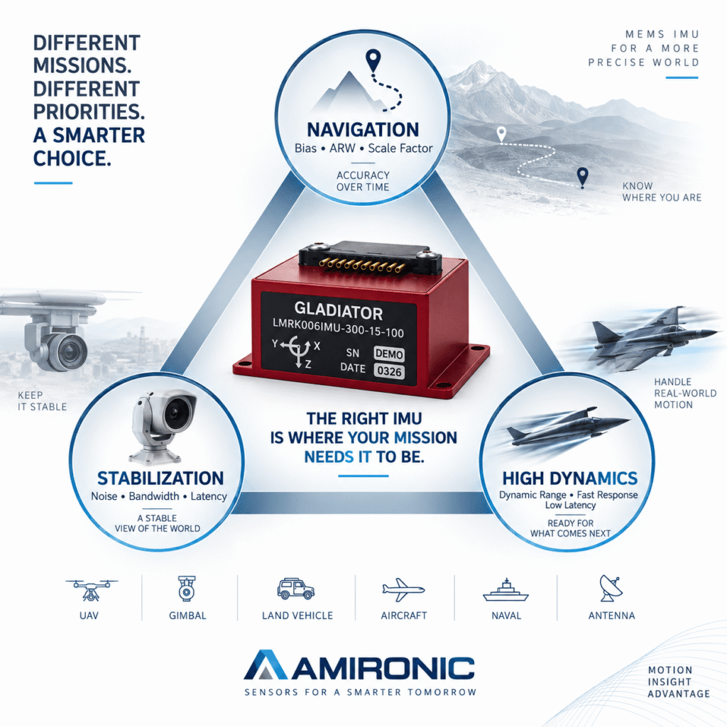
The term dynamic system covers a very broad range of applications. An electro-optical Gimbal, UAV, Antenna Positioning system, tracking system, autonomous vehicle, and Guidance system may all use a MEMS IMU or MEMS Gyroscope, but their sensor requirements can be very different.

This is why the term Tactical Grade IMU alone is not enough to select the right product.

Two IMUs may belong to the same general performance class while being designed around a different balance of Bias, Noise, Bandwidth, Latency, and Dynamic Range.

For example, a navigation system may place greater emphasis on Bias Instability, Angular Random Walk, and stability over temperature, while a fast stabilization system may give greater weight to Low Noise, High Bandwidth, and Low Latency.

In a system that experiences aggressive maneuvers, High Dynamic Range also becomes important, ensuring that the Gyroscope and Accelerometer do not reach saturation precisely when the inertial data is needed most.

The question, therefore, is not simply whether an IMU is “Tactical Grade,” but:

What tactical-grade performance does the specific mission actually require?


Navigation vs. Stabilization – Same MEMS Technology, Different Priorities

The difference between an IMU for navigation and an IMU for stabilization and control clearly demonstrates why a sensor cannot be selected based on a single parameter.

MEMS IMU for Navigation

When an IMU is used as part of an inertial navigation system, particularly when there are periods without GNSS or another external aiding source, small errors can accumulate over time.

In this case, parameters that should be carefully evaluated include:

Bias Instability, Bias Repeatability, Angular Random Walk, Scale Factor, Temperature Stability, and Calibration.

The longer the system must continue navigating without an external update, the more important its long-term inertial performance becomes.

MEMS IMU for Stabilization and Control

In a stabilization system, the priorities may be very different.

Consider a MEMS Gyroscope installed in the Gimbal of an EO/IR system. Its purpose is not simply to determine what the orientation was several seconds ago. It must detect motion and feed the control loop quickly enough to maintain a stable Line of Sight.

This brings other parameters into focus:

Bandwidth, Noise, Latency, Sampling, Data Rate, Synchronization, and Dynamic Range.

If the sensor responds too slowly, filters out important motion, or introduces significant delay, even outstanding Bias performance may not be enough to deliver the required stabilization performance.


What Happens When You Need Both Navigation and Dynamic Performance?

This is where IMU selection becomes more interesting.

Many systems do not fit neatly into a single category.

A UAV, autonomous drone, Guidance system, mobile EO/IR system, or military platform may simultaneously require:

  • Good long-term inertial accuracy
  • Fast response to maneuvers
  • Low Noise
  • High Bandwidth
  • Low Latency
  • Wide Angular Rate Range
  • Vibration and Shock resistance
  • Performance over a wide temperature range
  • Low Size, Weight, and Power

At this point, it is no longer possible to simply select the MEMS IMU with the best specification in every category, because real-world engineering involves trade-offs.

The objective is to find the right balance for the system.


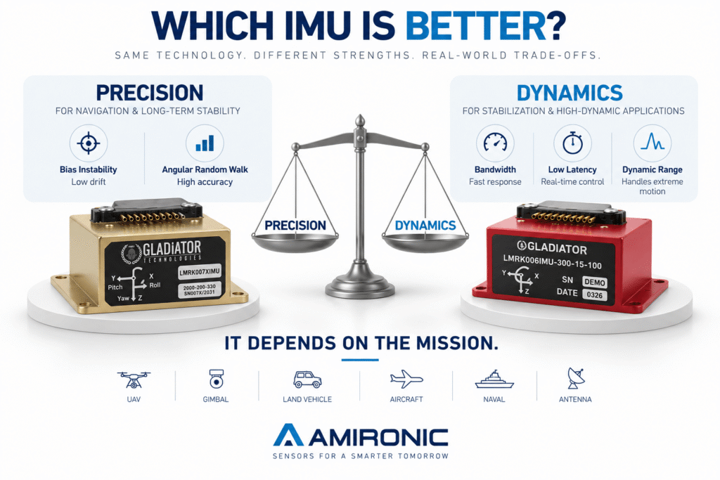
Precision vs. Dynamics – The Comparison Table Trap

Suppose an engineer receives two quotations for Tactical IMUs.

The engineer creates an Excel table and starts comparing the products line by line.

The first IMU has lower Bias.

✓

Its ARW is also better.

✓

At this point, it is tempting to conclude that this IMU is “more accurate” and therefore the better choice.

But then the comparison continues.

The second IMU offers wider Bandwidth, significantly lower Latency, and a higher Angular Rate Range.

Now the answer is no longer so obvious.

If the application is relatively slow Navigation, the advantages of the first IMU may be significant.

If the application involves High-Dynamic Stabilization, the advantages of the second IMU may matter more to actual system performance.

This is exactly why it is misleading to create a simple IMU ranking:

1st place, 2nd place, 3rd place.

The ranking changes when the application changes.


Start With the Motion Profile, Not the Datasheet

Before selecting a MEMS Gyroscope or MEMS IMU, it is important to describe the motion that the sensor will actually experience in the real world.

Four basic questions can completely change the selection:

1. What is the typical angular rate?
The system may operate most of the time at 20°/s or at 200°/s.

2. What is the maximum angular rate?
Not the average, but the most extreme event that the system is still required to measure.

3. At what frequencies does the motion relevant to the control system occur?
This is where the Bandwidth requirement begins to take shape.

4. How quickly does the system need to respond?
This is where Latency, Data Rate, and Synchronization requirements become important.

Only after understanding the Motion Profile can we determine whether ±300°/s is sufficient, whether ±2,000°/s is required, what Bandwidth is needed, and how much delay the system can tolerate.


Headroom – Don’t Design the Gyroscope Right at the Limit

Suppose the calculations show that the platform is expected to reach a maximum angular rate of 280°/s.

Is a ±300°/s Gyroscope the right choice?

Not necessarily.

Real systems experience events that are not always captured by the initial model: a more aggressive maneuver than expected, Vibration, Shock, changing operating conditions, or simultaneous motion across multiple axes.

For this reason, selecting the Dynamic Range of a MEMS Gyroscope should include an appropriate margin.

On the other hand, this does not mean that a wider range is always better.

If the application never approaches high angular rates, there is no automatic advantage in selecting a range of several thousand degrees per second.

Again, the same principle applies:

The biggest number is not necessarily the best specification. The best specification is the one that matches the actual dynamics of the system.


What Should Be Defined Before Requesting a MEMS IMU Quotation?

Instead of sending an RFQ that simply says:

“Need tactical grade IMU with low bias”

it is better to provide a broader engineering picture.

At a minimum:

Requirement What to Define
Application Navigation / Stabilization / Tracking / Guidance
Platform UAV / Gimbal / Vehicle / Antenna / Other
Gyro Range Typical and maximum angular rate
Accelerometer Range Typical and maximum acceleration
Bias Required long-term performance
Noise / ARW According to the application
Bandwidth Required frequency range
Data Rate Required system data rate
Latency Maximum acceptable delay
External Sync Whether synchronization with other sensors is required
Temperature Operating range and required performance
Vibration / Shock Mechanical operating environment
Interface RS-422 / CAN / SPI / Other
SWaP Size, Weight, and Power constraints

It is not necessary to know the exact answer to every one of these parameters in advance.

In fact, one of the benefits of working with an experienced MEMS IMU and MEMS Gyroscope manufacturer is the ability to translate application-level requirements into sensor-level requirements.

But the better the system is described, the lower the risk of selecting an IMU because one specification looks excellent on the datasheet even though it is not the parameter limiting actual system performance.


The Best IMU Is Not Necessarily the One That Wins the Datasheet Comparison

This may be the most important point when selecting a Tactical Grade IMU for a dynamic system.

When comparing MEMS IMUs, it is easy to look for a winner:

The lowest Bias.
The lowest ARW.
The highest Bandwidth.
The highest Data Rate.
The widest Dynamic Range.

But a real system is not a datasheet competition.

The right MEMS IMU is the one in which Bias, Noise, Bandwidth, Latency, and Dynamic Range are balanced according to the system’s Mission Profile.

Sometimes this means selecting an IMU with better Bias performance.

Sometimes a MEMS Gyroscope with faster dynamic response will be the right choice.

And sometimes the application requires a solution that balances both worlds – a Tactical IMU that combines high inertial performance with the ability to operate in a highly dynamic system.

Does a Tactical Grade IMU Automatically Mean the Sensor Is Suitable for a Dynamic System?

Not necessarily.

The term Tactical Grade IMU is commonly used to describe a high-performance inertial sensor, but by itself it does not define whether the sensor is suitable for a specific application.

Even within the world of Tactical IMUs, there can be significant differences in architecture, calibration, and the balance between key performance parameters.

Two MEMS IMUs may both offer excellent Bias performance, yet one may be better suited to navigation while the other is optimized for applications that require High Bandwidth, Low Latency, and High Dynamic Range.

Therefore, a requirement that simply states:

“Tactical Grade, low bias, 3-axis IMU”

is still not enough to make the right engineering selection.

In a dynamic system, it is necessary to understand not only how accurate the sensor is, but also how quickly it can measure change, how long it takes for the data to reach the system, and what happens as the motion approaches the limits of the measurement range.


What About Data Rate? More Hz Does Not Necessarily Mean a Faster IMU

This is one of the easiest specifications to misinterpret.

Suppose a MEMS IMU provides an Output Data Rate of 2,000 Hz or even 10 kHz.

That number is certainly interesting, but by itself it does not mean that the sensor can track physical motion over the same frequency range.

It is important to distinguish between three different concepts:

Sampling Rate – the rate at which the internal system samples the sensor.

Output Data Rate – the rate at which new measurement data is delivered to the host system.

Bandwidth – the frequency range of physical motion that the sensor can measure and transmit in a useful way.

There is also Latency – the time between the physical event and the availability of the relevant information at the output.

This is why two MEMS Gyroscopes with the same Data Rate can behave very differently inside a control system.

For Gimbal Stabilization, EO/IR, Antenna Positioning, Tracking Systems, and UAV Control, these differences may be far more important than the large number shown next to “Output Rate” on the datasheet.


Latency and Bandwidth Are Not the Same Thing

These two parameters are also often confused.

Bandwidth describes the frequency range of motion that the sensor can measure and transmit effectively.

Latency describes how much time passes before that information becomes available.

A MEMS Gyroscope may offer wide Bandwidth, but if internal processing, Digital Filtering, or the communication chain introduces significant Delay, the control loop still receives the information later.

In a slow system, a few milliseconds may be insignificant.

In a highly dynamic system, they may be critical.

As angular rate increases and as the control-system Bandwidth becomes wider, the importance of a Low-Latency IMU also increases.

Therefore, when comparing a MEMS IMU for stabilization, it is useful to examine the complete signal chain:

Sensor → Filtering → Processing → Output → Control Loop

and not only the data rate at the output interface.


What About Scale Factor and Temperature?

So far, the focus has been on Bias, Noise, Bandwidth, Latency, and Dynamic Range, but real systems involve additional parameters that should not be ignored.

One of them is Scale Factor Error.

If a Gyroscope is measuring an angular rate of 500°/s and there is a Scale Factor Error, its impact may be more significant than during very slow motion.

In systems with High Dynamic Range, it is therefore not enough for the MEMS Gyroscope to measure high angular rates without reaching Saturation. It is also important to understand how accurately it measures throughout that range.

The same principle applies to temperature.

A military system, UAV, or electro-optical platform does not always operate at 25°C.

Temperature changes can affect Bias, Scale Factor, and other parameters, which is why Temperature Calibration and stability over the operating temperature range are part of the overall picture when selecting a Tactical Grade MEMS IMU.


Vibration Can Also Change the Picture

A MEMS IMU datasheet is characterized under defined conditions. The real platform may be far less forgiving.

A UAV has motors and propellers.
A vehicle moves over uneven terrain.
An EO/IR system is mounted on a moving platform.
An airborne system may experience Vibration, Shock, and maneuvers at the same time.

Mechanical vibration can enter the measurement range of the MEMS Gyroscope and Accelerometer and influence the quality of the data reaching the algorithm.

For this reason, selecting an IMU for a dynamic system should also take into account the actual vibration environment of the platform, the mounting configuration, and the frequency ranges in which significant vibration energy is present.

An IMU that performs extremely well on the laboratory bench is not necessarily the sensor that will deliver the best result after integration onto the platform.


The Five Parameters Must Be Evaluated Together

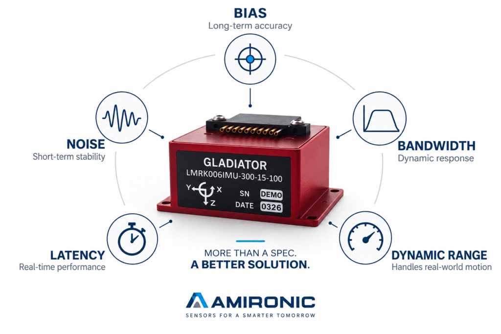
The core of the selection process can be summarized as follows:

Parameter The Question to Ask
Bias How important is long-term measurement stability?
Noise How much noise can the control loop tolerate?
Bandwidth What dynamics must the sensor be able to see?
Latency How quickly must the information reach the system?
Dynamic Range What is the maximum motion that must be measured without Saturation?

But even this table is not a formula.

There is no fixed ratio that says Bias is 30% of the decision, Bandwidth is 25%, and Latency is 20%.

The mission determines the weight of each parameter.

In a Navigation system, the balance may shift toward Bias, ARW, and Scale Factor.

In a Stabilization system, the emphasis may shift toward Noise, Bandwidth, and Latency.

And in a High-Dynamic system that combines navigation and control, the challenge is to find a MEMS IMU that balances both worlds.


This Is Exactly Why Different MEMS IMU Families Exist

A manufacturer of MEMS Gyroscopes and Tactical Grade IMUs is not necessarily trying to create one product that wins every line of the datasheet.

Different applications require different optimization points.

An IMU designed for Navigation may emphasize Bias, ARW, and stability.

An IMU designed for Stabilization and Control may emphasize dynamic response, Bandwidth, Noise, and Latency.

An IMU designed for High-Dynamic Applications may also require very wide Angular Rate Range and Acceleration Range.

This is also one of the reasons why Gladiator Technologies MEMS IMU families include solutions with different combinations of performance characteristics.

The goal is not to choose the part number with the most impressive individual specification.

The goal is to match the MEMS IMU or MEMS Gyroscope to the Mission Profile, platform dynamics, and control-system architecture.


Before Selecting an IMU, Change the Question

Instead of asking:

“Which IMU is the most accurate?”

ask:

“What type of accuracy and performance does my system actually need?”

Is the primary challenge long-term Drift?

Does the system need to maintain Line of Sight during rapid motion?

Are high angular rates expected?

Is the Control Loop sensitive to Latency?

Is the platform exposed to significant Vibration?

Does the system need to continue operating when GNSS is unavailable?

Is External Sync required with a Camera, Radar, Encoder, or other sensors?

The answers to these questions are more important than trying to find a MEMS IMU with the best number in a single specification.


A Useful Rule of Thumb

Navigation asks: How accurately can I know where I am over time?

Stabilization asks: How accurately and how quickly can I detect what is happening now?

High-Dynamic Control asks: Can I still do both when the platform starts moving aggressively?

That is the difference between selecting an IMU by the Datasheet and selecting an IMU for the system.

What Does the Right IMU Selection Process Look Like in Practice?

At this stage, the principles can be turned into a structured engineering process.

Selecting a MEMS IMU for a dynamic system should not begin with the question, “Which model has the lower Bias?” It should begin with defining the mission and the conditions in which the sensor is expected to operate.

A practical selection flow can look like this:

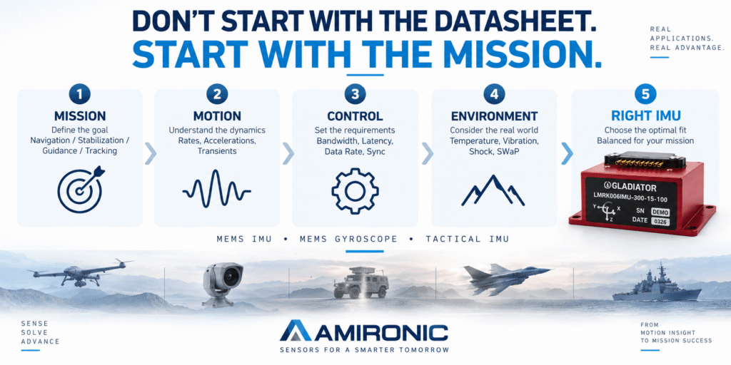
Mission → Motion Profile → Control Requirements → Environment → IMU Performance → Integration

Each stage narrows the range of possible solutions and helps identify which performance parameters really matter.

1. Define the Mission

Is the system used for:

  • Navigation
  • Stabilization
  • Guidance
  • Tracking
  • Pointing
  • Attitude Estimation
  • Dead Reckoning
  • Motion Control

At this stage alone, it is often possible to determine whether the application is driven primarily by Precision, by Dynamics, or by a combination of both.

2. Define the Motion Profile

What angular rates and accelerations will the system actually experience?

Not only during normal operation, but also during:

Maximum Maneuvers, Shock, Vibration, and Transient Events.

This is where requirements for Gyro Range, Accelerometer Range, and overall Dynamic Range begin to take shape.

3. Define the Control-Loop Requirements

If the MEMS Gyroscope is part of a stabilization or control loop, several questions become important:

What Bandwidth is required?
What update rate is required?
How much Latency can the system tolerate?
Is External Sync required?

These are very different questions from asking how good the Bias specification is.

4. Define the Operating Environment

Temperature, Vibration, Shock, mechanical constraints, and SWaP can change the selection even when two IMUs appear very similar in terms of inertial performance.

5. Only Now Open the Datasheet

At this stage, the numbers on the datasheet finally have context.

Instead of simply looking for the lowest Bias or the highest Bandwidth, the engineer can evaluate whether:

Bias, ARW, Noise, Bandwidth, Latency, Dynamic Range, Scale Factor, and Temperature Performance

actually match the requirements that were defined.


Example: A UAV That Must Both Navigate and Stabilize a Payload

Consider a typical system where the selection is not one-dimensional.

A UAV carries a stabilized EO/IR payload.

On one side, the navigation system requires high-quality inertial data. If GNSS becomes degraded, blocked, or jammed, Bias, ARW, and Scale Factor become more important.

On the other side, the payload must maintain Line of Sight while the aircraft maneuvers, vibrates, or changes direction.

For the stabilization system, parameters such as:

Noise, Bandwidth, Latency, and the ability to follow the platform’s dynamic motion

become critical.

Now assume that the UAV performs an aggressive maneuver.

If the MEMS Gyroscope reaches Saturation, the stabilization system may lose information precisely when it needs it most.

This is why Dynamic Range is not separate from accuracy. Both are part of the same mission requirement.

It is a classic example of how selecting a Tactical Grade IMU based on Bias alone can optimize the wrong parameter.


Another Example: A Gimbal for an EO/IR System

In a fast Gimbal, the purpose of the IMU is not only to provide accurate angular information, but to provide it at the right time for the control loop.

Suppose two MEMS Gyroscopes both offer excellent Bias performance.

The first has better Bias specifications, but slower dynamic response.

The second has slightly worse Bias, but lower Noise in the relevant frequency range, wider Bandwidth, and lower Latency.

If the goal is to maintain Line of Sight on a target while the platform is moving, the second Gyroscope may very well be the better engineering choice.

Not because Bias is unimportant.

But because, in this system, the parameter limiting performance is somewhere else.


The Opposite Example: Navigation During GNSS-Denied Operation

Now consider a different system.

The platform does not perform particularly aggressive maneuvers, but it must continue estimating its motion and orientation when GNSS is unavailable.

Here, the priorities may change.

A Dynamic Range of several thousand degrees per second may have little practical value if the platform never approaches those angular rates.

By contrast, improvements in Bias Instability, Angular Random Walk, Scale Factor, and Temperature Stability may provide significantly more value.

The same MEMS IMU that is excellent for High-Dynamic Stabilization is not necessarily the optimal choice for Dead Reckoning.

Again:

There is no universally better IMU. There is an IMU that is better suited to the mission.


Do Not Define a Requirement That Has No Direct Link to System Performance

This is especially important when writing a specification or RFQ for a Tactical IMU.

It is very easy to copy a parameter from an existing product or take the best number found online and turn it into a requirement.

For example:

Bias Instability ≤ X °/hr

But why exactly X?

What happens to system performance if the value is slightly higher?

Is this truly the requirement that limits navigation or stabilization performance?

The same applies to:

10 kHz Data Rate
±2,000°/s Gyro Range
600 Hz Bandwidth
Ultra-low ARW

All of these can be valuable performance characteristics.

But they should be requirements derived from the system, not numbers selected because they look impressive on a datasheet.

Over-specifying can unnecessarily reduce the number of available solutions, increase cost, increase SWaP, or lead to a sensor that is poorly balanced for the application.


What Should You Send to a MEMS IMU Manufacturer?

To receive a meaningful recommendation for a MEMS IMU or MEMS Gyroscope, it is not always necessary to arrive with a specification that is dozens of pages long.

In many cases, a good description of the application is more useful than a long list of numbers.

At a minimum, it is useful to provide:

Information Example
Application Navigation / Gimbal / EO/IR / Guidance
Platform UAV / Aircraft / Vehicle / Naval
Typical Angular Rate °/s
Maximum Angular Rate °/s
Acceleration Range g
Required Bandwidth Hz
Maximum Latency µs / ms
Navigation Requirement GNSS-denied duration / allowable Drift
Temperature Range °C
Vibration / Shock Environmental profile
Interface RS-422 / CAN / SPI / Other
External Sync Required / Not Required
Size / Weight / Power SWaP constraints
Existing IMU If the project is a replacement

And what if some of these parameters are not yet known?

That is not necessarily a problem.

This is exactly where engineering support from a manufacturer specializing in MEMS Gyroscopes, MEMS IMUs, and Tactical Grade IMUs becomes valuable.

The customer does not need to design the sensor. The objective is to provide enough information about the mission so that the right sensor can be selected.


Gladiator Technologies – Matching the IMU to the Mission

This approach is especially relevant when working with a broad family of MEMS Inertial Sensors.

Gladiator Technologies develops MEMS Gyroscopes and MEMS IMUs for Navigation, Stabilization, Guidance, Control, and other demanding dynamic applications.

The key point is not to find one model that “wins” every specification.

The value is in matching system requirements with the right combination of performance characteristics – Bias, Noise, Bandwidth, Latency, Dynamic Range, interfaces, SWaP, and environmental requirements.

That is why the correct selection process starts with the application and only then moves to the part number.


Conclusion – Do Not Look for the IMU With the Best Datasheet

Selecting a MEMS IMU for a dynamic system is an exercise in balance.

Low Bias does not necessarily compensate for inadequate Bandwidth.

High Bandwidth does not compensate for excessive Noise.

A high Data Rate does not guarantee low Latency.

A wide Dynamic Range is not an advantage if the system does not need it.

And a Tactical Grade IMU is not automatically suitable for every tactical system.

The right selection starts with understanding the Mission Profile, followed by the Motion Profile, navigation requirements, control-loop requirements, operating environment, and integration constraints.

Only then can different MEMS IMUs, MEMS Gyroscopes, and Tactical IMUs be compared correctly.

The best IMU is not the one with the most impressive number in the table.

The best IMU is the one that delivers the performance the system needs, when it needs it, across the entire mission envelope.

Case Study – Three Sensors, Three Different Optimization Points

To see how trade-offs between Bias, Noise, Bandwidth, Latency, and Dynamic Range affect the selection of a MEMS IMU or MEMS Gyroscope, we can compare three solutions from the Gladiator Technologies product family:

G400D, LandMark 006 IMU, and LandMark 007 IMU.

The objective is not to determine which product is “better,” but to understand how different numerical specifications align with different system requirements.

It is also important to note that the G400D is a triaxial MEMS Gyroscope, while the LandMark 006 and LandMark 007 are IMUs that include both Gyroscopes and Accelerometers. The G400D is available in three performance grades, and in this Case Study we will refer to the highest-performance G400D-300-100C version.

Performance Comparison

Parameter G400D-300-100C LandMark 006 IMU LandMark 007 IMU
Gyro Range ±300°/s ±300°/s ±2,000°/s
Accelerometer Range – ±15g ±98g
Gyro ARW 0.0254°/√hr 0.0254°/√hr 0.09°/√hr*
Bias In-Run 0.8°/h 0.8°/h 4°/h
Bias Over Temperature 35°/h 35°/h 0.075°/s = 270°/h
Scale Factor Error 500 ppm 500 ppm ≤0.03% = ≤300 ppm
Max Bandwidth – VELOX Plus 600 Hz 600 Hz 600 Hz
Data Rate – VELOX Plus 10 kHz 10 kHz 10 kHz
Digital Message Delay – VELOX Plus 20 µs 20 µs 114 µs
Operational Vibration 8 gRMS 8 gRMS 15 gRMS
Operational Shock 1,000g, 0.5 ms 1,000g, 0.5 ms 1,000g, 1 ms
Calibrated Temperature -50°C to +85°C -50°C to +85°C -50°C to +85°C
Mass 17 ±1 g 17 ±1 g 25 ±1 g

The G400D specifications include a ±300°/s range, ARW of 0.0254°/√hr, Bias In-Run of 0.8°/h, and Scale Factor Error of 500 ppm. With VELOX Plus, it provides up to 600 Hz Bandwidth, 10 kHz Data Rate, and 20 µs Digital Message Delay.

The LandMark 006 provides the same ±300°/s Gyro range, 0.0254°/√hr ARW, 0.8°/h Bias Stability, and 500 ppm Scale Factor Error, while adding an Accelerometer with a ±15g range.

The LandMark 007, by contrast, operates in a completely different dynamic envelope: up to ±2,000°/s Gyro range and ±98g Accelerometer range. Its datasheet explicitly defines it as a High Dynamic IMU.

*In the LandMark 007 datasheet, ARW is shown both as 0.002°/s/√Hz and as 0.09°/√hr. For this comparison, we use the 0.09°/√hr value shown in the performance table.


Case 1 – A Stabilization System Where Bias, Noise, and Latency Matter

Suppose we are designing a Gimbal with a maximum expected angular rate of:

±200°/s

Both the G400D and LandMark 006, with a ±300°/s range, provide a Headroom of:

300 – 200 = 100°/s

or approximately 50% above the maximum angular rate of the application.

In this type of application, there is no practical advantage to the LandMark 007 being able to measure up to ±2,000°/s, because the system never approaches that range.

The other differences now become more interesting.

LandMark 006 offers:

Bias In-Run: 0.8°/h
ARW: 0.0254°/√hr
Bandwidth: 600 Hz
Message Delay: 20 µs

Compared with LandMark 007:

Bias In-Run: 4°/h
ARW: 0.09°/√hr
Bandwidth: 600 Hz
Message Delay: 114 µs

According to the datasheets, LandMark 006 therefore provides:

5× lower Bias In-Run

and an ARW lower by approximately:

0.09 / 0.0254 ≈ 3.54

With VELOX Plus, its Message Delay is also lower by a factor of:

114 / 20 = 5.7

Both IMUs provide up to 600 Hz Bandwidth and 10 kHz Data Rate, but their specified message delays are significantly different.

If the platform rotates at 200°/s, during 20 µs it moves:

200 × 0.000020 = 0.004°

During 114 µs it moves:

200 × 0.000114 = 0.0228°

This does not necessarily represent actual Gimbal error, but it illustrates the difference in the amount of physical motion that occurs during the Message Delay.

In an application where ±300°/s is sufficient, LandMark 006 can represent a very attractive balance between Precision and Dynamics.


Case 2 – The Same System, but Now It Reaches 500°/s

Now change only one requirement.

Suppose the platform can reach:

500°/s

during a maneuver.

Suddenly, the comparison changes completely.

LandMark 006 is limited to:

±300°/s

so at 500°/s, the requirement exceeds its measurement range by:

200°/s

LandMark 007, on the other hand, provides:

±2,000°/s

At 500°/s, it is using only:

500 / 2000 = 25%

of its full Gyro range.

That leaves a Headroom of:

1,500°/s

At this point, we can debate 0.8°/h Bias versus 4°/h Bias as much as we like.

If the ±300°/s sensor reaches Saturation during a maneuver that the system must measure, a Bias-based comparison is no longer addressing the primary requirement.

LandMark 007 was designed precisely for this kind of operating envelope: ±2,000°/s in the Gyro and ±98g in the Accelerometer.

This is exactly the kind of case where an IMU that appears “less accurate” in some datasheet parameters may actually be the better choice for the dynamic system.


Case 3 – A System That Experiences High Acceleration

Here, the difference is even more pronounced.

LandMark 006:

±15g Accelerometer Range

LandMark 007:

±98g Accelerometer Range

Suppose the platform can experience a transient of:

30g

LandMark 006 is already outside its specified measurement range.

LandMark 007 uses only approximately:

30 / 98 ≈ 30.6%

of its acceleration range.

If the event reaches 60g:

60 / 98 ≈ 61.2%

of the LandMark 007 range is used.

In a High-Dynamic system, therefore, a 98g range is not simply “a bigger number on the datasheet.” It can represent a functional requirement that determines whether the sensor continues measuring or reaches Saturation.

The specified acceleration ranges are ±15g for LandMark 006 and ±98g for LandMark 007.


Case 4 – The Vibration Environment Changes the Selection Again

Suppose the system is installed on a platform with a vibration requirement of:

12 gRMS

LandMark 006 is rated for:

8 gRMS, 50 Hz to 2 kHz

LandMark 007 is rated for:

15 gRMS, 50 Hz to 2 kHz Random

In this case, the 12 gRMS requirement exceeds the operational specification of LandMark 006 but remains within the specified range of LandMark 007.

Again, even better Bias performance does not change the fact that the environmental requirement itself can eliminate one product from consideration.

This demonstrates why Vibration and Shock should be part of the Tactical IMU selection process at the RFQ stage, rather than something checked only after the sensor has already been selected.


Case 5 – What If the System Does Not Need an Accelerometer at All?

This is where the G400D comes in.

Suppose the system already includes Accelerometers elsewhere, or the Control Loop only requires three-axis Angular Rate measurements.

In that case, there may be no reason to use a 6-axis MEMS IMU.

The G400D is a Triaxial MEMS Gyroscope, and the 300-100C version provides:

±300°/s
0.0254°/√hr ARW
0.8°/h Bias In-Run
500 ppm Scale Factor Error
600 Hz Maximum Bandwidth
10 kHz Data Rate
20 µs Digital Message Delay

all at a mass of:

17 ±1 g

and a volume of:

0.63 in³ / 10.2 cm³

In this case, the question is not:

“Which is better, G400D or LandMark 006?”

but rather:

“Does the system actually need an IMU, or does it need a triaxial MEMS Gyroscope?”

That is a System Architecture decision, not a Datasheet decision.


What Do the Numbers Actually Tell Us?

We can now summarize the three products in a more meaningful way than simply “good / better / best”:

Mission Requirement Potentially Better Fit Main Reason
3-axis Angular Rate only G400D Triaxial Gyro without Accelerometer
Precision + Stabilization up to ±300°/s LandMark 006 0.8°/h Bias, 0.0254°/√hr ARW, 600 Hz, 20 µs
High Angular Dynamics LandMark 007 Up to ±2,000°/s
High Linear Dynamics LandMark 007 Up to ±98g
Vibration above 8 gRMS and up to 15 gRMS LandMark 007 15 gRMS rating
Low Message Delay G400D / LandMark 006 20 µs with VELOX Plus
Navigation / Stabilization where ±15g is sufficient LandMark 006 Balance of Precision and 6-axis IMU capability

And this is the key lesson from the Case Study:

LandMark 006 offers better Bias and ARW performance than LandMark 007, but LandMark 007 can measure dynamic conditions that LandMark 006 was simply not designed to measure.

And conversely:

If the application never exceeds ±300°/s or ±15g, a ±2,000°/s Gyro range and ±98g Accelerometer range do not automatically make LandMark 007 the better choice.

The most impressive number does not decide. The Mission Profile does.

🧩 Further Reading and Deeper Insight

This article is part of a broader series exploring the engineering principles behind modern inertial sensing and motion stability in advanced control and navigation systems. For deeper technical context and system-level insights, you may also find the following articles valuable:

  • Bridging Control and Navigation: How Advanced MEMS IMUs Are Redefining System Performance
  • Gyro and IMU for Advanced Control Systems
  • The Silent Problem of Precision Systems – Why Gyros and IMUs Are Control Components, Not Just Sensors
  • Why External Sync is Critical in Gyro and IMU Systems
  • Stabilization, Tracking & Time Sync: The Foundation of Precise Line-of-Sight Control
  • Mission-Grade Stabilization in Dynamic EO/IR Systems: Why Bandwidth, Data Rate, and Phase Lag Define Gimbal Performance
  • Why Gladiator? What Truly Differentiates a High-End MEMS IMU Manufacturer
  • Common Misconceptions About MEMS Inertial Sensors
  • Bias Stability vs. Bias Instability: What really determines the performance of Gyro and IMU systems in stabilization, tracking, and navigation
  • Scale Factor in MEMS IMUs – The Error That Quietly Destroys Accuracy
  • The IMU Was Excellent. The Image Still Shook.
  • 2000Hz IMU? Before You Get Impressed, Understand Three Completely Different Numbers
  • SX3: Pushing MEMS Beyond Traditional Stabilization
  • Why a Smaller IMU Can Save Months of Development
  • Your Image Still Shakes Despite Choosing a Gyroscope with Excellent Bias Stability
  • Why Replacing an IMU Can Lead to Weeks of Recalibration
  • From IMU to INS: How a Tactical Navigation System Is Really Built
  • When GPS Is Lost, It’s Already Too Late to Choose an IMU
  • Why Do Counter-UAS Systems Lose Track of a Drone Right After Detecting It?
  • When GPS Lies: Why IMUs Are Becoming Mission-Critical in the Era of Autonomous Wingmen
  • How Does a MEMS Sensor Become a Tactical-Grade IMU?
  • The Antenna Hasn’t Moved – So Why Did We Lose the Link? The Role of the IMU in Antenna Positioning Systems
  • Tactical Grade IMU: What Happens When the Mission Stops Behaving Like the Lab?

Frequently Asked Questions – FAQ

Is an IMU with Lower Bias Instability Always a Better IMU?

No. Bias Instability is a very important parameter when selecting a MEMS IMU or MEMS Gyroscope, especially for navigation and GNSS-Denied applications, but it does not define overall system performance by itself.

In dynamic systems, other parameters must also be evaluated, including Noise, Bandwidth, Latency, Dynamic Range, Scale Factor, and environmental conditions.

For example, the LandMark 006 offers a Bias Stability of 0.8°/h, while the LandMark 007 specifies 4°/h. However, the LandMark 007 provides a Gyro range of up to ±2,000°/s, compared with ±300°/s for the LandMark 006.

What Is the Difference Between a MEMS Gyroscope and a MEMS IMU?

A MEMS Gyroscope measures angular rate.

A MEMS IMU typically combines Gyroscopes and Accelerometers across multiple axes to measure both angular motion and linear acceleration.

For example, the G400D is a triaxial Gyroscope, while the LandMark 006 is a Six-Axis IMU that includes a ±300°/s Gyro and a ±15g Accelerometer.

What Is a Tactical Grade IMU?

A Tactical Grade IMU is a term commonly used to describe an IMU with high inertial performance suitable for demanding applications.

However, the term alone is not sufficient for sensor selection. The actual numerical specifications must be evaluated against the Mission Profile, including:

Bias, ARW, Noise, Bandwidth, Latency, Dynamic Range, Scale Factor, Temperature, Vibration, and Shock.

Does a Higher Data Rate Mean the IMU Is Faster?

Not necessarily.

Data Rate, Bandwidth, and Latency are different parameters.

For example, the LandMark 006 and LandMark 007 both provide up to 10 kHz Data Rate and 600 Hz Bandwidth with VELOX Plus, but their specified Digital Message Delay differs significantly: 20 µs for the LandMark 006 versus 114 µs for the LandMark 007.

Why Is Latency Important When Selecting an IMU for Stabilization?

In a dynamic control system, the sensor must not only measure motion accurately but also deliver that information in time.

The faster the platform moves, the farther it can move during the measurement delay.

For this reason, a Low-Latency MEMS IMU can be especially important in Gimbals, EO/IR systems, Tracking Systems, Antenna Stabilization, and fast Control applications.

What Is Dynamic Range in a MEMS IMU?

Dynamic Range describes the range of motion that the sensor can measure.

For a Gyroscope, this includes the Angular Rate Range. For an Accelerometer, it includes the acceleration range.

The LandMark 007 is designed for High-Dynamic applications and provides a Gyro range of up to ±2,000°/s and an Accelerometer range of up to ±98g.

Should You Always Choose the Gyroscope With the Widest Range?

No.

A wider measurement range is not automatically an advantage.

If the system never approaches high angular rates, other parameters such as Bias, Noise, ARW, or Latency may be more important.

The required range should be selected according to:

Typical Motion → Maximum Expected Motion → Transients → Margin

What Is More Important for a Gimbal – Bias or Bandwidth?

There is no single answer.

In a fast Gimbal Stabilization system, Noise, Bandwidth, and Latency can have a major effect on control-loop performance.

Bias remains important, but all parameters should be evaluated together rather than selecting a MEMS Gyroscope based only on its Bias specification.

What Is More Important for Navigation Without GNSS?

In Navigation and GNSS-Denied applications, parameters that influence accumulated error generally become more important, including:

Bias, Angular Random Walk, Scale Factor, and stability over temperature.

The longer the system must operate without an external aiding source, the more important the long-term inertial performance becomes.

How Do You Select a MEMS IMU for a Dynamic System?

Start with the mission, not the Datasheet:

Mission → Motion Profile → Control Requirements → Environment → IMU Performance → Integration

Only after defining angular rates, accelerations, Bandwidth, Latency, environmental conditions, and navigation requirements can different MEMS IMUs, MEMS Gyroscopes, and Tactical IMUs be compared correctly.


Important Terms

MEMS – Micro-Electro-Mechanical Systems
A technology used to manufacture miniature mechanical structures and sensors using microelectronic fabrication processes. MEMS technology is widely used in Gyroscopes and Accelerometers.

MEMS Gyroscope
An inertial sensor based on MEMS technology that measures angular rate. A triaxial Gyroscope measures angular rate around three axes.

MEMS IMU – Inertial Measurement Unit
An inertial measurement unit that combines multiple sensors. A Six-Axis IMU typically includes three Gyroscope axes and three Accelerometer axes.

Tactical Grade IMU
An IMU with high inertial performance intended for demanding applications such as Navigation, Stabilization, Guidance, and Control. The numerical specifications of each product should always be evaluated rather than relying on the Tactical Grade designation alone.

Bias
An offset in the sensor output. In a Gyroscope, it means the sensor may report a non-zero angular rate even when the actual angular rate differs from that reported value.

Bias Instability / Bias Stability
A measure describing the stability of the sensor Bias over time under defined measurement conditions. Lower values can be especially important in inertial navigation applications.

Bias Over Temperature
The change in Bias across the temperature range. For example, the LandMark 006 specifies a Gyro Bias Over Temperature of 35°/h across its calibrated temperature range of -50°C to +85°C.

ARW – Angular Random Walk
A measure of Gyroscope angular noise that contributes to accumulated uncertainty in angle estimation over time.

Noise Density
The sensor’s noise density relative to Bandwidth. This parameter is especially important when evaluating how sensor noise may affect a control system or Sensor Fusion algorithm.

Bandwidth
The frequency range over which the sensor can track motion in a useful way. High Bandwidth can be especially important in dynamic stabilization and control systems.

Data Rate / Output Data Rate
The rate at which the sensor provides new measurement data to the system. A high Data Rate is not the same as high Bandwidth and does not guarantee low Latency.

Latency / Digital Message Delay
The delay between the physical motion or measurement event and the availability of that information to the system. In fast dynamic applications, even tens or hundreds of microseconds may be relevant to control-loop design.

Dynamic Range
The range of motion the sensor can measure. For a Gyroscope, it is commonly expressed in °/s. For an Accelerometer, it is commonly expressed in g.

Saturation
A condition in which the actual motion exceeds the measurement range of the sensor. For example, a Gyroscope with a ±300°/s range cannot fully represent an angular rate of 500°/s.

Scale Factor Error
The error in the relationship between the actual physical motion and the value reported by the sensor. Scale Factor Error can become especially significant at high angular rates or accelerations.

G-Sensitivity
The sensitivity of the Gyroscope output to linear acceleration. This parameter can be important when the Gyroscope operates in an environment with significant acceleration or Vibration.

Vibration Rectification Error – VRE
An error that can result from exposure to vibration. It is particularly relevant for MEMS IMUs installed on UAVs, vehicles, and other platforms with significant vibration environments.

External Sync
The ability to synchronize IMU measurements with an external clock or event. This can be particularly useful in systems that combine Cameras, Radar, GNSS, Encoders, or other sensors.

Motion Profile
A description of the expected platform dynamics, including angular rates, accelerations, maneuvers, Transients, Vibration, and Shock.

Mission Profile
The complete set of mission conditions and required system performance. The Mission Profile should be the starting point for defining MEMS IMU requirements, not the other way around.

SWaP – Size, Weight and Power
Size, Weight, and Power constraints. These are especially important in UAVs, airborne systems, Payloads, and compact platforms.

VELOX / VELOX Plus
Sensor interface and processing configurations referenced in Gladiator datasheets. In the LandMark 006, for example, VELOX Plus provides up to 10 kHz Data Rate, 10 kHz External Sync, 600 Hz Maximum Bandwidth, and 20 µs Digital Message Delay.

Tags: Gladiator_Technologies

Related Articles

Why Position Feedback Matters More Than Ever in Counter-UAS Swarm Defense

02/08/2026amironicLTD

Why a Smaller IMU Can Save Months of Development

30/06/2026amironicLTD

The IMU Was Excellent. The Image Still Shook.

01/06/2026amironicLTD

Recent Posts

  • How to Choose an IMU for a Dynamic System – Why “More Accurate” Doesn’t Always Mean “Better”
  • Electrical, Pneumatic, USB, Bluetooth or Contactless – How Do You Choose the Right Switch for Your System?
  • Military DC-DC Converters with Built-In EMI Filtering and Input Protection
  • MIL-STD-1275 vs. MIL-STD-704 – What’s the Difference and How Do You Choose the Right Power Supply?
  • You Don’t Always Need to Measure Temperature – Sometimes You Just Need to Know When to Stop

Categories

  • Air Switch
  • Circuit Breakers
  • Elapsed Time Indicator
  • Feedthrough
  • Footswitches
  • Gears & Transmission
  • Hour Meters
  • Infra Red Switches
  • INFRARED LAMPS
  • Low Noise Inertial MEMS
  • Mechanics
  • MEMS Gyroscope
  • MEMS Inertial
  • Microelectronics
  • Motors
  • Position Sensors
  • Power Supply
  • Pressure Sensors
  • Pressure Switch
  • Temperature Sensors
  • Tungsten and Molybdenum
  • Uncategorized
  • Vacuum Switches

Quick Contact

Fill out the form and our representatives will return to you

    Name (required)

    Email (required)

    Phone

    Message

    This site is protected by reCAPTCHA and the Google
    Privacy Policy and
    Terms of Service apply.

    Amironic Ltd.

    3 Rabinovich Street, Petah Tikva 4928144 , Israel. Tel: +972-3-9047744 E-mail: office@amironic.co.il
    Email
    Facebook
    Twitter
    LinkedIn
    YouTube
    Press on the ISO Certificate below for download
    ISO 9001:2015 Certification
    • MEMS Inertial
    • Circuit Breakers
    • Footswitches
    • Mechanical & Transmisions
    • Sensors
    • Motors
    • Electronics
    • Hand Control
    • Power Solutions

    News

    • How to Choose an IMU for a Dynamic System – Why “More Accurate” Doesn’t Always Mean “Better”
    • Electrical, Pneumatic, USB, Bluetooth or Contactless – How Do You Choose the Right Switch for Your System?
    • Military DC-DC Converters with Built-In EMI Filtering and Input Protection
    • MIL-STD-1275 vs. MIL-STD-704 – What’s the Difference and How Do You Choose the Right Power Supply?
    • You Don’t Always Need to Measure Temperature – Sometimes You Just Need to Know When to Stop
    About AmironicContactעברית
    © 2022 Amironic All rights reserved. All Trademarks are the property of their respective owners.
    • Increase Font
    • Decrease Font
    • Black & White
    • Inverse Colors
    • Highlight Links
    • Regular Font
    • Reset