In a system that moves slowly and predictably, it is relatively easy to evaluate the performance of an IMU – Inertial Measurement Unit.
Connect the sensor, examine the bias, look at the noise level, evaluate stability over time, and the results may look excellent.
But real-world aerospace and defense systems do not always behave like a laboratory bench.
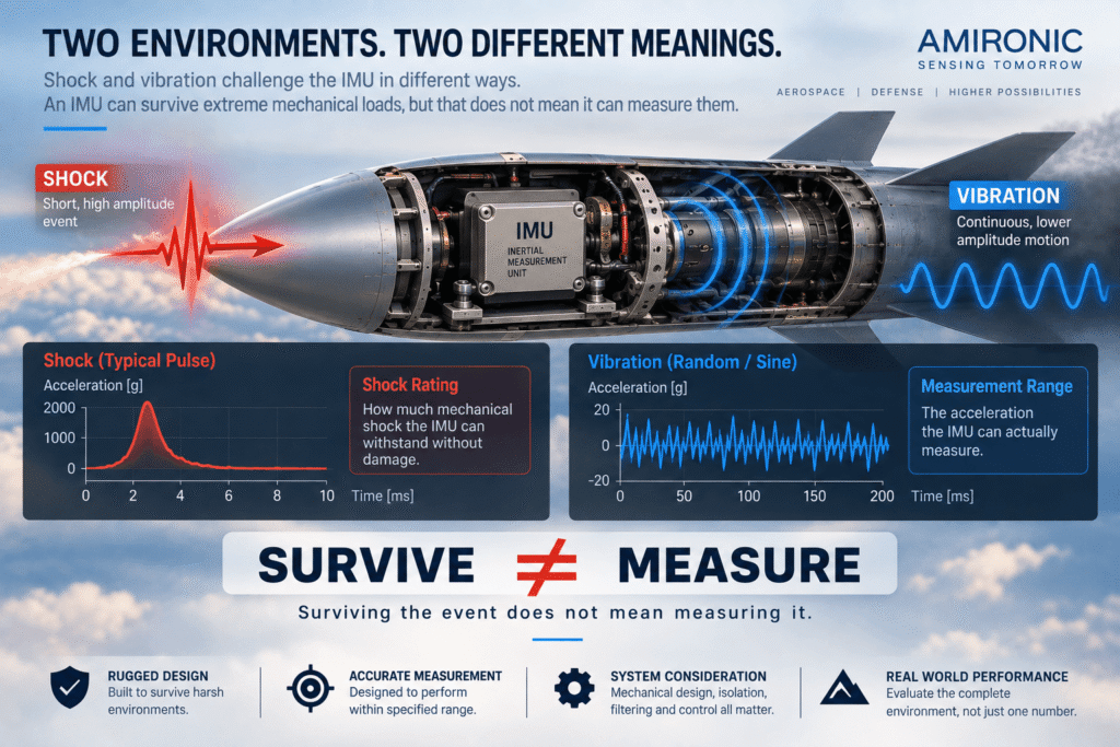
An airborne platform may change direction rapidly. A stabilized system may experience a sudden mechanical disturbance. An autonomous vehicle may transition from a smooth surface into a severe vibration environment. In demanding aerospace and defense applications, a Tactical IMU may also be exposed to high acceleration, mechanical shock, vibration and very high angular rates.
Under these conditions, the engineering question changes:
It is no longer only how accurate the IMU is when the system is stable, but what happens to the measurement when the dynamics become extreme.
This is why selecting a High-Dynamic IMU requires looking beyond familiar specifications such as Bias Stability and Angle Random Walk (ARW).
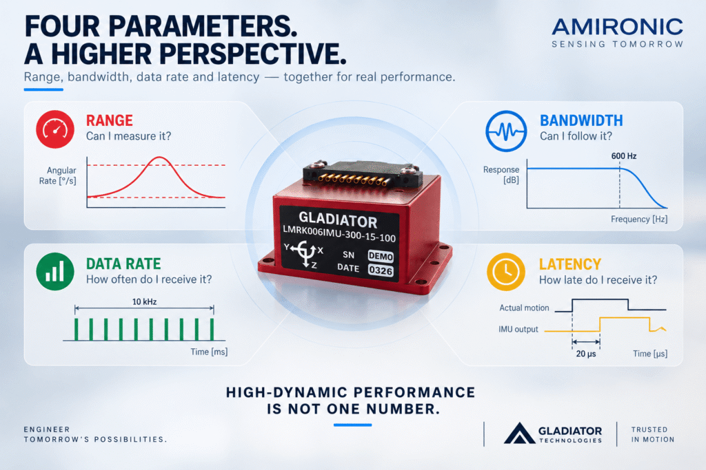
The engineer must also consider gyroscope and accelerometer measurement ranges, bandwidth, data rate, latency, shock and vibration performance, acceleration sensitivity, and the ability of the MEMS IMU to continue delivering useful inertial data while the platform itself becomes increasingly difficult to measure.
What Is a High-Dynamic IMU?
The term High-Dynamic IMU does not necessarily describe a single standardized performance category or a universally defined numerical threshold.
Instead, it generally refers to an IMU that must provide useful inertial measurements while the platform experiences rapid changes in angular rate and acceleration, often combined with significant shock and vibration.
In a high-dynamic system, several conditions may occur simultaneously:
- Angular rate can increase rapidly.
- Acceleration can change within a very short period.
- The platform structure can generate vibration across a wide frequency spectrum.
- The control system may require inertial data at a very high update rate.
- The delay between physical motion and the arrival of usable sensor data can become significant.
- The gyroscope or accelerometer may approach its full-scale measurement limits.
This means that an IMU that looks excellent according to one specification may be less suitable when the complete operating environment is considered.
For example, a MEMS gyroscope with very low noise provides little benefit if the actual angular rate exceeds its measurement range and the sensor saturates.
Likewise, a wide measurement range alone is not sufficient if the sensor bandwidth or latency cannot support the dynamics of the control system.
High-Dynamic performance is therefore not one number in an IMU datasheet. It is the relationship between platform motion, sensor limitations and control-system requirements.
For engineers selecting a Tactical Grade IMU for aerospace, defense, autonomous platforms or other high-performance control applications, understanding that relationship is far more useful than simply comparing the lowest Bias Stability number.
When an IMU Stops Seeing What Is Really Happening
Consider a platform performing a rapid maneuver.
As long as the angular rate remains within the full-scale range of the gyroscope, the motion can be measured.
But suppose the MEMS Gyroscope is configured for ±300°/s and the platform briefly exceeds that limit.
The sensor does not simply continue measuring with slightly reduced accuracy.
It has reached saturation.
Once this happens, the output can no longer represent the full physical motion experienced by the platform.
If the control or navigation algorithm integrates angular-rate measurements to estimate changes in orientation or attitude, even a short period of unmeasured motion can introduce an error into the attitude estimate.
This illustrates an important principle when selecting a High-Dynamic Tactical IMU:
Measurement range is not merely a sensor specification. It determines which motions the system can actually measure.
The correct question is therefore not:
“Is ±300°/s a large gyroscope range?”
The better question is:
“What is the maximum angular rate my platform can generate, including transients and abnormal but operationally relevant events?”
The same principle applies to the accelerometer.
A system that normally operates near 1g may experience much higher acceleration for short periods. If the accelerometer measurement range does not cover these events, the inertial measurement can saturate precisely when the platform reaches its most demanding dynamic condition.
±300°/s or ±2000°/s – Is a Wider IMU Range Always Better?
It is tempting to conclude that the safest solution is simply to select the widest available measurement range.
That is not necessarily the correct engineering decision.
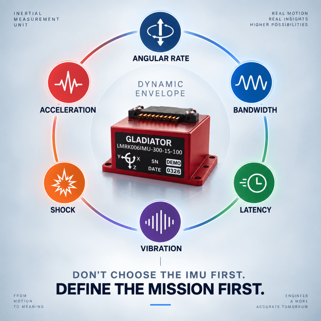
Measurement Range should not be considered in isolation. Depending on the sensor architecture and configuration, range may be related to Noise, Resolution, Scale Factor and other performance characteristics. The objective is therefore not to select the IMU with the largest number in the datasheet, but to select a range that matches the actual Dynamic Envelope of the application.
The Gladiator Technologies LandMark IMU family provides a useful example.
The LandMark 006 IMU is a compact six-axis Tactical Grade MEMS IMU combining three MEMS gyroscopes and three accelerometers. It offers a gyroscope range of ±300°/s and an accelerometer range of ±15g. In the VELOX PLUS configuration, it supports bandwidth up to 600 Hz and data rates up to 10 kHz, together with a very low digital message delay of approximately 20 µs.
These characteristics make the Gladiator LandMark 006 particularly interesting for high-performance control, stabilization, autonomous systems and aerospace applications that require fast inertial data while remaining within this dynamic range.
The Gladiator Technologies LandMark 007 IMU, by contrast, was developed specifically for High Dynamic Applications. It extends the available dynamic envelope significantly, with gyroscope ranges up to ±2000°/s and accelerometer ranges up to ±98g. The LandMark 007 also uses Gladiator’s high-speed VELOX architecture, with VELOX PLUS configurations supporting high data rates and bandwidth up to 600 Hz.
Both are high-performance MEMS IMUs.
Both are designed for demanding applications.
But they address very different dynamic envelopes.
That is where proper Tactical IMU selection begins.
The question is not whether the LandMark 006 or LandMark 007 is the “better” IMU.
The real engineering question is:
Which Gladiator Technologies IMU is matched to the motion, acceleration, shock, vibration and control-loop requirements that the platform will actually experience?